transmission CHRYSLER PACIFICA 2019 Owners Manual
[x] Cancel search | Manufacturer: CHRYSLER, Model Year: 2019, Model line: PACIFICA, Model: CHRYSLER PACIFICA 2019Pages: 718, PDF Size: 8.6 MB
Page 6 of 718
INTRODUCTION
Dear Customer,
Congratulations on selecting your new vehicle. Be assured
that it represents precision workmanship, distinctive styl-
ing, and high quality. This Owner ’s Manual has been
prepared with the assistance of service and engineering
specialists to acquaint you with the operation and mainte-
nance of your vehicle. It is supplemented by Warranty
Information, and customer oriented documents. In the
attached Warranty Booklet, you will find a description of
the services that FCA offers to its customers, the Warranty
Certificate and the details of the terms and conditions for
maintaining its validity. Please take the time to read all of
these publications carefully before driving your vehicle for
the first time. Following the instructions, recommenda-
tions, tips, and important warnings in this manual will
help assure safe and enjoyable operation of your vehicle.
Be sure you are familiar with all vehicle controls, particu-
larly those used for braking, steering, transmission, and
transfer case shifting (if equipped). Learn how your vehicle
handles on different road surfaces. Your driving skills will
improve with experience.This Owner ’s Manual describes all versions of this vehicle.
Options and equipment dedicated to specific markets or
versions are not expressly indicated in the text. Therefore,
you should only consider the information which is related
to the trim level, engine, and version that you have
purchased. Any content introduced throughout the Own-
er ’s Information, that may or may not be applicable to your
vehicle, will be identified with the wording “If Equipped”.
All data contained in this publication are intended to help
you use your vehicle in the best possible way. FCA aims at
a constant improvement of the vehicles produced. For this
reason, it reserves the right to make changes to the model
described for technical and/or commercial reasons. For
further information, contact an authorized dealer.
NOTE:
After reviewing the Owner ’s Information, it should
be stored in the vehicle for convenient referencing, and
remain with the vehicle when sold.
When it comes to service, remember that an authorized
dealer knows your vehicle best, has factory-trained techni-
cians and genuine MOPAR® parts, and cares about your
satisfaction.
4 INTRODUCTION
Page 50 of 718
location below the door handle(s). Do not move your foot
sideways or in a sweeping motion or the sensors may not
detect the motion.
When a valid kicking motion is completed, the sliding door
will chime, the hazard lights will flash and the sliding door
will open almost instantaneously. This assumes all options
are enabled in the radio settings.
NOTE:
•To open the Hands-Free Sliding Doors requires a valid
Passive Entry key fob within 5 ft (1.5 m) of the door
handle. If a valid Passive Entry key fob is not within 5 ft
(1.5 m), the door will not respond to any kicks.
• The Hands-Free Sliding Door will only operate when the
transmission is in PARK.
• With every movement of the Hands-Free sliding doors,
an audible tone will sound and the turn signals will
flash. Refer to “Uconnect Settings” in “Multimedia” in
the Owner ’s Manual for further information on turning
these alerts on or off.
• If anything obstructs the power sliding side door while
it is closing or opening, the door will automatically
reverse to the closed or open position and an audible tone will sound, provided it meets sufficient resistance.
The turn signals will flash with sliding door movements.
• If the power sliding doors encounters multiple obstruc-
tions within the same cycle, the system will automati-
cally stop.
The Hands-Free Sliding Doors feature may be turned off
through Uconnect Settings. Refer to “Uconnect Settings” in
“Multimedia” for further information. The Hands-Free
Sliding Doors feature should be turned off during Jacking,
Tire Changing, and Vehicle Service.
Child Locks
To provide a safer environment for small children riding in
the rear seats, the sliding doors are equipped with a Child
Protection Door Lock system.
To Engage The Child Protection Door Lock
1. Open the sliding side door.
2. On the rear of the sliding door, slide the Child Protection Door Lock control inward (toward the vehicle) to en-
gage the Child Protection Door Lock.
48 GETTING TO KNOW YOUR VEHICLE
Page 147 of 718
HOOD
Opening
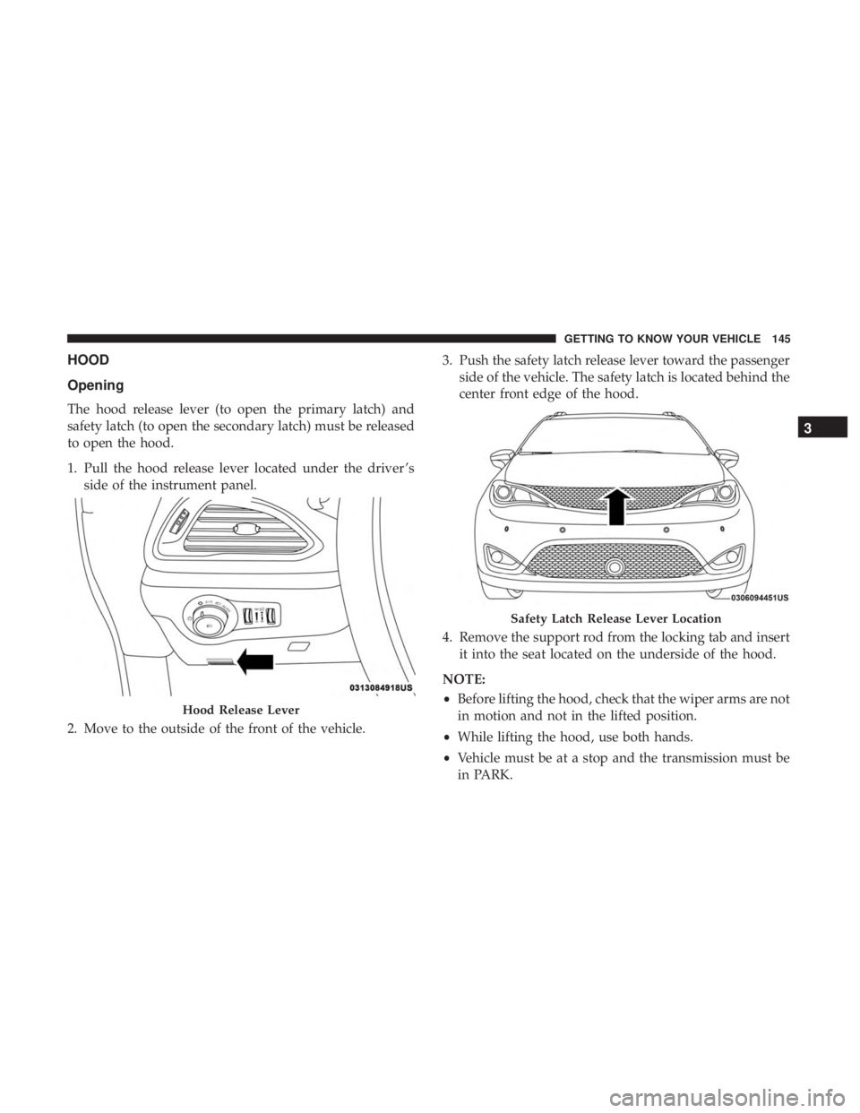
The hood release lever (to open the primary latch) and
safety latch (to open the secondary latch) must be released
to open the hood.
1. Pull the hood release lever located under the driver ’sside of the instrument panel.
2. Move to the outside of the front of the vehicle. 3. Push the safety latch release lever toward the passenger
side of the vehicle. The safety latch is located behind the
center front edge of the hood.
4. Remove the support rod from the locking tab and insert it into the seat located on the underside of the hood.
NOTE:
• Before lifting the hood, check that the wiper arms are not
in motion and not in the lifted position.
• While lifting the hood, use both hands.
• Vehicle must be at a stop and the transmission must be
in PARK.
Hood Release Lever
Safety Latch Release Lever Location
3
GETTING TO KNOW YOUR VEHICLE 145
Page 153 of 718
NOTE:To open the Hands-Free Liftgate requires a valid
Passive Entry key fob within 5 ft (1.5 m) of the door handle.
If a valid Passive Entry key fob is not within 5 ft (1.5 m), the
liftgate will not respond to any kicks.
CAUTION!
The Hands-Free Liftgate feature may be turned on or
off in Uconnect Settings. Refer to “Uconnect Settings”
in “Multimedia” for further information. The Hands-
Free Liftgate feature should be turned off during
Jacking, Tire Changing, and Vehicle Service.
NOTE:
• The Hands-Free Liftgate will only operate when the
transmission is in PARK.
• If anything obstructs the Hands-Free liftgate while it is
opening or closing, the liftgate will automatically re-
verse to the closed position, provided it meets sufficient
resistance.
• There are pinch sensors attached to the side of the
liftgate opening. Light pressure anywhere along these
strips will cause the liftgate to return to the open
position. •
If the power liftgate encounters multiple obstructions
within the same cycle, the system will automatically
stop. If this occurs, the liftgate must be operated manu-
ally.
• The power liftgate will release, but not power open, in
temperatures below �12° F (�24° C). Be sure to remove
any buildup of snow or ice from the liftgate before
opening the liftgate.
• If the liftgate is left open for an extended period of time,
the liftgate may need to be closed manually to reset
power liftgate functionality.
WARNING!
• Driving with the liftgate open can allow poisonous
exhaust gases into your vehicle. You and your pas-
sengers could be injured by these fumes. Keep the
liftgate closed when you are operating the vehicle.
• If you are required to drive with the liftgate open,
make sure that all windows are closed, and the
climate control blower switch is set at high speed. Do
not use the recirculation mode.
3
GETTING TO KNOW YOUR VEHICLE 151
Page 156 of 718
WARNING!(Continued)
•Do not allow to be used as a toy. Close attention is
necessary when used by or near children.
• Do not leave the vacuum running while unattended.
• Use only as described in this manual. Use only
attachments provided with your vehicle.
• Do not put any object into openings. Do not use with
any opening blocked; keep free of dust, lint, hair,
and anything that may reduce air flow.
• Do not vacuum toxic material such as chlorine
bleach, ammonia, drain cleaner, etc.
• Do not vacuum hard or sharp objects such as glass,
nails, screws, coins, etc.
• Keep hair, loose clothing, fingers, and all parts of
body away from openings and moving parts.
• Only use with filter in place. Periodically check that
the filter is in place and in good condition.
WARNING!
This equipment incorporates parts such as switches,
motors, or the like that tend to produce arcs or sparks
that can cause an explosion. When using your vacuum
(Continued)
WARNING! (Continued)
near gasoline-dispensing equipment or service sta-
tions, park vehicle at least 20 ft (6 m) away from the
exterior enclosure of any dispensing pump. The
vacuum is mounted more than 18 inches (45 cm) above
ground level in your vehicle.
1. Before Using Vacuum:
Accessory (ACC) Mode Operation - For up to 10 minutes
of operation
Always apply the parking brake, shift the transmission into
PARK, and push ignition button to place ignition in
Accessory (ACC) mode. The engine will not be running in
this mode. Do not leave the key fob in or near the vehicle,
or in a location accessible to children.
NOTE: The vacuum system will run for 10 minutes off
battery power and then the vacuum will shut down. A low
battery indication light (LOW PWR) located below the
vacuum nozzle storage location will come on one minute
before the vacuum shuts down.
154 GETTING TO KNOW YOUR VEHICLE
Page 157 of 718
Engine Running (ON) Operation - For more than 10
minutes of operation•Position vehicle outdoors and fully open all side
windows.
• Always apply the parking brake, shift the transmission
into PARK, and leave engine running.
WARNING!
Carbon monoxide (CO) in exhaust gases can cause
serious injury or death. Follow the precautions below
to prevent carbon monoxide poisoning:
• Do not inhale exhaust gases.
• Do not start or run an engine in a closed garage or
confined area. Always position vehicle outdoors and
fully open all side windows before using vacuum
system with the engine running.
• Guard against carbon monoxide with proper main-
tenance. Have the exhaust system inspected every
time the vehicle is raised. Have any abnormal condi-
tions repaired promptly.
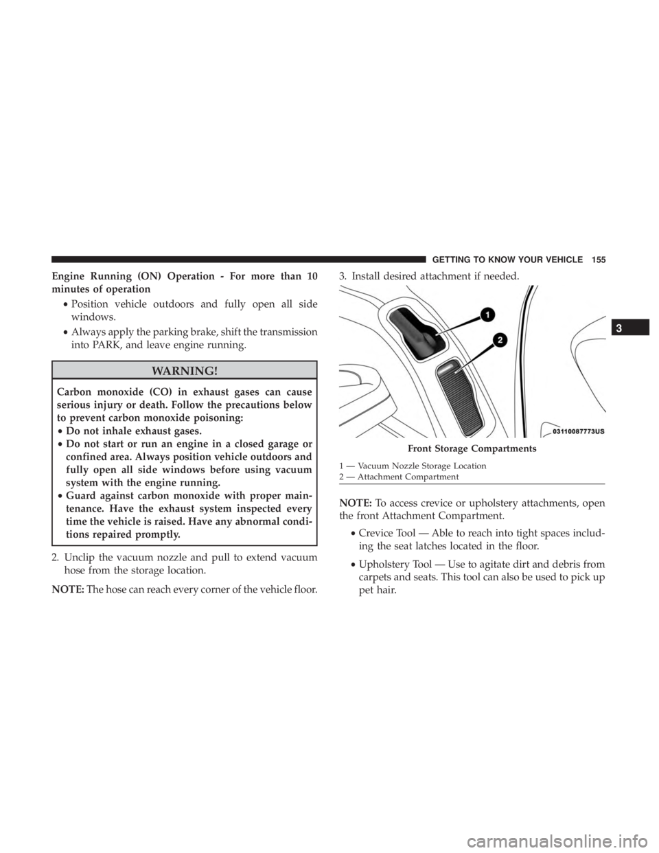
2. Unclip the vacuum nozzle and pull to extend vacuum hose from the storage location.
NOTE: The hose can reach every corner of the vehicle floor. 3. Install desired attachment if needed.
NOTE:
To access crevice or upholstery attachments, open
the front Attachment Compartment.
•Crevice Tool — Able to reach into tight spaces includ-
ing the seat latches located in the floor.
• Upholstery Tool — Use to agitate dirt and debris from
carpets and seats. This tool can also be used to pick up
pet hair.
Front Storage Compartments
1 — Vacuum Nozzle Storage Location
2 — Attachment Compartment
3
GETTING TO KNOW YOUR VEHICLE 155
Page 162 of 718
2. Return to vacuum nozzle storage location located be-hind the sliding door.
3. Grab the vacuum nozzle and gently pull the hose out through vacuum nozzle storage location.
4. Shake the hose to remove any objects stuck in the hose. Take care not to perforate the hose while attempting to
dislodge any objects.
5. Reverse the procedure to reinstall and clip the hose into place.
GARAGE DOOR OPENER — IF EQUIPPED
HomeLink replaces up to three hand-held transmitters that
operate devices such as garage door openers, motorized
gates, lighting or home security systems. The HomeLink
unit is powered by your vehicle’s 12 Volt battery.
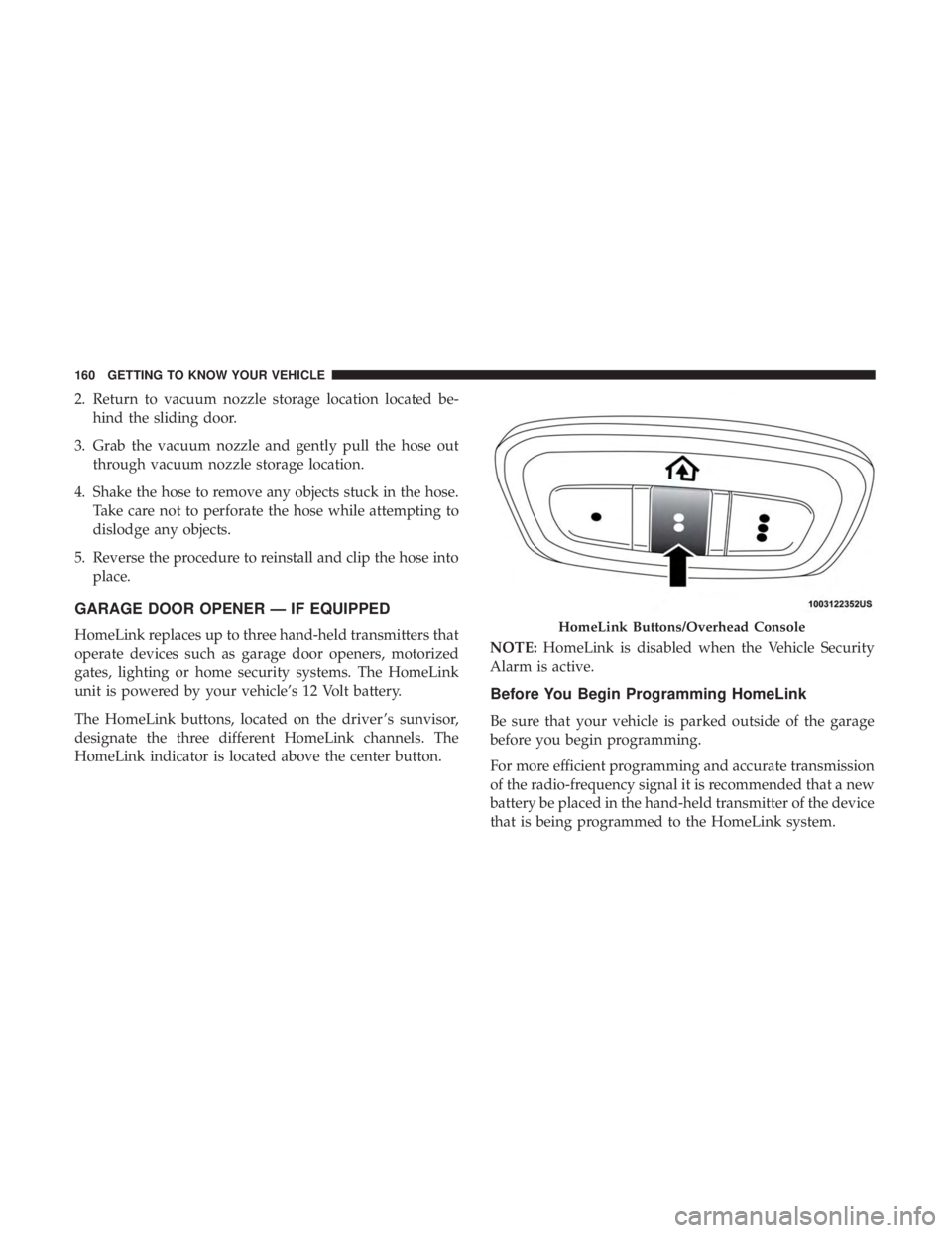
The HomeLink buttons, located on the driver ’s sunvisor,
designate the three different HomeLink channels. The
HomeLink indicator is located above the center button. NOTE:
HomeLink is disabled when the Vehicle Security
Alarm is active.
Before You Begin Programming HomeLink
Be sure that your vehicle is parked outside of the garage
before you begin programming.
For more efficient programming and accurate transmission
of the radio-frequency signal it is recommended that a new
battery be placed in the hand-held transmitter of the device
that is being programmed to the HomeLink system.
HomeLink Buttons/Overhead Console
160 GETTING TO KNOW YOUR VEHICLE
Page 165 of 718
3. Press and hold the HomeLink button you want toprogram while you press and hold the hand-held trans-
mitter button.
4. Continue to hold both buttons and observe the indicator light. The HomeLink indicator will flash slowly and
then rapidly after HomeLink has received the frequency
signal from the hand-held transmitter. Release both
buttons after the indicator light changes from slow to
rapid.
5. Press and hold the programmed HomeLink button and observe the indicator light.
• If the indicator light stays on constantly, programming
is complete and the garage door/device should acti-
vate when the HomeLink button is pressed.
• To program the two remaining HomeLink buttons,
repeat each step for each remaining button. DO NOT
erase the channels.
Reprogramming A Single HomeLink Button (Non-
Rolling Code)
To reprogram a channel that has been previously trained,
follow these steps:
1. Cycle the ignition to the ON/RUN position. 2. Press and hold the desired HomeLink button until the
indicator light begins to flash after 20 seconds. Do not
release the button.
3. Without releasing the button, proceed with “Program- ming A Non-Rolling Code” step 2 and follow all remain-
ing steps.
Canadian/Gate Operator Programming
For programming transmitters in Canada/United States
that require the transmitter signals to “time-out” after
several seconds of transmission.
Canadian radio frequency laws require transmitter signals
to time-out (or quit) after several seconds of transmission –
which may not be long enough for HomeLink to pick up
the signal during programming. Similar to this Canadian
law, some U.S. gate operators are designed to time-out in
the same manner.
It may be helpful to unplug the device during the cycling
process to prevent possible overheating of the garage door
or gate motor.
1. Cycle the ignition to the ON/RUN position.
3
GETTING TO KNOW YOUR VEHICLE 163
Page 199 of 718
Instrument Cluster Display Menu Items
NOTE:The instrument cluster display menu items display
in the center of the instrument cluster. Menu items may
vary depending on your vehicle features.
Speedometer
Push and release the upordown arrow button until
Speedometer is highlighted in the instrument cluster dis-
play. Push and release the OKbutton to toggle between
MPH and km/h.
Vehicle Info
Push and release the upordown arrow button until
Vehicle Info is highlighted in the instrument cluster dis-
play. Push the leftorright arrow button to scroll through
the following information submenus:
Tire Pressure
If tire pressure is OKfor all tires, a vehicle ICON is
displayed with tire pressure values in each corner of the
ICON.
If one or more tires have low pressure, “Inflate Tire To XX”
is displayed with the vehicle ICON, and the tire pressure values in each corner of the ICON with the pressure value
of the low tire displayed in a different color than the other
tire pressure value.
If the Tire Pressure system requires service, “Service Tire
Pressure System” is displayed.
Tire PSI is an information only function and cannot be
reset. Refer to “Tire Pressure Monitoring System (TPMS)”
under “Safety” for further information.
Coolant Temperature
Displays the actual coolant temperature.
Transmission Temperature
Displays the actual transmission temperature.
Oil Temperature
Displays the actual oil temperature.
Oil Pressure
Displays the actual oil pressure.
Battery Voltage
Displays the actual battery voltage.
4
GETTING TO KNOW YOUR INSTRUMENT PANEL 197
Page 209 of 718
— Electronic Throttle Control (ETC) Warning
Light
This warning light will illuminate to indicate a problem
with the Electronic Throttle Control (ETC) system. If a
problem is detected while the vehicle is running, the light
will either stay on or flash depending on the nature of the
problem. Cycle the ignition when the vehicle is safely and
completely stopped and the transmission is placed in the
PARK position. The light should turn off. If the light
remains on with the vehicle running, your vehicle will
usually be drivable; however, see an authorized dealer for
service as soon as possible.
NOTE: This light may turn on if the accelerator and brake
pedals are pressed at the same time.
If the light continues to flash when the vehicle is running,
immediate service is required and you may experience
reduced performance, an elevated/rough idle, or engine
stall and your vehicle may require towing. The light will
come on when the ignition is placed in the ON/RUN or
ACC/ON/RUN position and remain on briefly as a bulb
check. If the light does not come on during starting, have
the system checked by an authorized dealer.
— Engine Coolant Temperature Warning Light
This warning light warns of an overheated engine condi-
tion. If the engine coolant temperature is too high, this
indicator will illuminate and a single chime will sound. If
the temperature reaches the upper limit, a continuous
chime will sound for four minutes or until the engine is
able to cool: whichever comes first.
If the light turns on while driving, safely pull over and stop
the vehicle. If the A/C system is on, turn it off. Also, shift
the transmission into NEUTRAL and idle the vehicle. If the
temperature reading does not return to normal, turn the
engine off immediately and call for service.
Refer to “If Your Engine Overheats” in “In Case Of
Emergency” for further information.
— Battery Charge Warning Light
This warning light will illuminate when the battery is not
charging properly. If it stays on while the engine is run-
ning, there may be a malfunction with the charging system.
Contact an authorized dealer as soon as possible.
This indicates a possible problem with the electrical system
or a related component.
4
GETTING TO KNOW YOUR INSTRUMENT PANEL 207