tire pressure CHRYSLER PACIFICA 2020 Owners Manual
[x] Cancel search | Manufacturer: CHRYSLER, Model Year: 2020, Model line: PACIFICA, Model: CHRYSLER PACIFICA 2020Pages: 516, PDF Size: 28.69 MB
Page 6 of 516
4
GETTING TO KNOW YOUR INSTRUMENT PANEL
INSTRUMENT CLUSTER..................................... 125
Instrument Cluster Descriptions ...............126
INSTRUMENT CLUSTER DISPLAY ................... 127
Instrument Cluster Display Location And
Controls ......................................................128 Oil Life Reset ..............................................129
Fuel And Oil Refresh Mode .......................129
KeySense Cluster Messages —
If Equipped .................................................130 Instrument Cluster Display Menu Items ..131
Battery Saver On/Battery Saver Mode
Message — Electrical Load Reduction
Actions — If Equipped ................................138 Instrument Cluster Display Programmable
Features Screen Setup.............................. 139
TRIP COMPUTER ............................................... 140
WARNING LIGHTS AND MESSAGES ............... 141
Red Warning Lights....................................141
Yellow Warning Lights ...............................144
Yellow Indicator Lights...............................147
Green Indicator Lights ...............................148
Blue Indicator Lights ..................................149White Indicator Lights................................149
ONBOARD DIAGNOSTIC SYSTEM — OBD II .... 150
Onboard Diagnostic System (OBD II)
Cybersecurity..............................................150
EMISSIONS INSPECTION AND MAINTENANCE
PROGRAMS ........................................................ 151
SAFETY
SAFETY FEATURES .............................................152 Anti-Lock Brake System (ABS) ................. 152
Electronic Brake Control (EBC) System ... 153
AUXILIARY DRIVING SYSTEMS.........................159 Blind Spot Monitoring (BSM) —
If Equipped ................................................. 159 Forward Collision Warning (FCW) With
Mitigation — If Equipped............................ 164 Tire Pressure Monitoring
System (TPMS) .......................................... 167
OCCUPANT RESTRAINT SYSTEMS .................. 171 Occupant Restraint Systems Features .... 171
Important Safety Precautions ................... 172
Seat Belt Systems ..................................... 172
Supplemental Restraint Systems (SRS)... 184
Child Restraints ......................................... 198
Transporting Pets ...................................... 215
SAFETY TIPS ....................................................... 216 Transporting Passengers .......................... 216Exhaust Gas .............................................. 216
Safety Checks You Should Make Inside
The Vehicle ................................................ 217 Periodic Safety Checks You Should Make
Outside The Vehicle ................................... 218
STARTING AND OPERATING
STARTING THE ENGINE .....................................219 Normal Starting.......................................... 219Cold Weather Operation (Below –22°F
Or −30°C) ................................................. 223 After Starting — Warming Up The
Engine ........................................................ 223 If Engine Fails To Start ............................. 223
To Turn Off The Engine Using ENGINE
START/STOP Button .................................. 223
ENGINE BLOCK HEATER — IF EQUIPPED ....... 224
ENGINE BREAK-IN RECOMMENDATIONS ...... 224
PARK BRAKE...................................................... 225 Electric Park Brake (EPB) ......................... 225
AUTOMATIC TRANSMISSION ........................... 228 Ignition Park Interlock ............................... 229Brake/Transmission Shift Interlock
System........................................................ 229 Nine-Speed Automatic Transmission ...... 230
Gear Ranges .............................................. 230
ACTIVE NOISE CANCELLATION ........................ 234
POWER STEERING............................................. 234
STOP/START SYSTEM — IF EQUIPPED ........... 235
Auto Stop/Start.......................................... 235
Possible Reasons The Engine Does Not
Autostop ..................................................... 235 To Start The Engine While In Auto
Stop/Start .................................................. 236 To Manually Turn Off The Stop/Start
System........................................................ 236 To Manually Turn On The Stop/Start
System........................................................ 237 System Malfunction................................... 237
20_RU_OM_EN_US_t.book Page 4
Page 8 of 516
6
IN CASE OF EMERGENCY
HAZARD WARNING FLASHERS ....................... 301
ASSIST AND SOS MIRROR — IF EQUIPPED.... 301
General Information ..................................305
BULB REPLACEMENT ....................................... 306
Replacement Bulbs ...................................306
Replacing Exterior Bulbs ...........................308
FUSES .................................................................. 311
General Information ..................................311Fuse Location.............................................312Underhood Fuses.......................................312
JACKING AND TIRE CHANGING —
IF EQUIPPED ....................................................... 320
Jack And Spare Tire Location....................320
Equipment Removal .................................320
Preparations For Jacking ..........................321
Jacking Instructions ..................................322Road Tire Installation ................................325Portable Air Compressor — If Equipped....327
Tire Service Kit For Inflating Tire —
If Equipped .................................................328 Return Inflatable Spare Tire ......................330
TIRE SERVICE KIT — IF EQUIPPED ................... 330
JUMP STARTING................................................. 337
Preparations For Jump Start .....................337Jump Starting Procedure...........................338
REFUELING IN EMERGENCY ............................ 339
IF YOUR ENGINE OVERHEATS .......................... 339 MANUAL PARK RELEASE ................................. 340
FREEING A STUCK VEHICLE .............................341
TOWING A DISABLED VEHICLE .......................342
ENHANCED ACCIDENT RESPONSE SYSTEM
(EARS) .................................................................344
EVENT DATA RECORDER (EDR) .......................344
SERVICING AND MAINTENANCE
SCHEDULED SERVICING .................................. 345
Maintenance Plan ..................................... 345
ENGINE COMPARTMENT ................................... 349
3.6L Engine ................................................ 349
Checking Oil Level ..................................... 350
Adding Washer Fluid ................................. 350
Maintenance-Free Battery ....................... 350
Pressure Washing...................................... 351
DEALER SERVICE ..............................................351
Engine Oil .................................................. 351
Engine Oil Filter .......................................... 352Engine Air Cleaner ..................................... 353
Accessory Drive Belt Inspection ............... 353
Air Conditioner Maintenance .................... 354
Body Lubrication ........................................ 356
Windshield Wiper Blades .......................... 356Exhaust System ........................................ 359
Cooling System .......................................... 361Brake System ............................................ 364Automatic Transmission ........................... 365 RAISING THE VEHICLE ...................................... 366
TIRES .................................................................. 366
Tire Safety Information.............................. 366
Tires — General Information .................... 374Tire Types ................................................... 378
Spare Tires — If Equipped ......................... 379
Wheel And Wheel Trim Care ..................... 381
Tire Chains (Traction Devices) ................. 382
Tire Rotation Recommendations.............. 382
DEPARTMENT OF TRANSPORTATION UNIFORM
TIRE QUALITY GRADES .................................... 383
Treadwear .................................................. 383
Traction Grades ......................................... 383Temperature Grades ................................. 384
STORING THE VEHICLE ..................................... 384
BODYWORK ........................................................ 385
Protection From Atmospheric Agents....... 385
Body And Underbody Maintenance .......... 385Preserving The Bodywork.......................... 385
INTERIORS ......................................................... 386
Seats And Fabric Parts .............................. 386
Plastic And Coated Parts........................... 387
Leather Parts ............................................. 387
Glass Surfaces .......................................... 387
20_RU_OM_EN_US_t.book Page 6
Page 104 of 516
102GETTING TO KNOW YOUR VEHICLE
(Continued)
NOTE:
To open the Hands-Free Liftgate requires a valid
Passive Entry key fob within 5 ft (1.5 m) of the
door handle. If a valid Passive Entry key fob is
not within 5 ft (1.5 m), the liftgate will not
respond to any kicks.
NOTE:
The Hands-Free Liftgate will only operate
when the transmission is in PARK.
If anything obstructs the Hands-Free Liftgate
while it is opening or closing, the liftgate will
automatically reverse to the closed position,
provided it meets sufficient resistance.
There are pinch sensors attached to the side
of the liftgate opening. Light pressure
anywhere along these strips will cause the
liftgate to return to the open position.
If the power liftgate encounters multiple
obstructions within the same cycle, the
system will automatically stop. If this occurs,
the liftgate must be operated manually.
The power liftgate will release, but not power
open, in temperatures below −12°F
(−24°C). Be sure to remove any buildup of
snow or ice from the liftgate before opening
the liftgate.
If the liftgate is left open for an extended
period of time, the liftgate may need to be
closed manually to reset power liftgate func-
tionality. Gas props support the liftgate in the open
position. However, because the gas pressure
drops with temperature, it may be necessary to
assist the props when opening the liftgate in
cold weather.
NOTE:
Allow the power system to open the liftgate.
Manually pushing or pulling the liftgate may
activate the liftgate obstacle detection feature
and stop the power operation or reverse its
direction.
CAUTION!
The Hands-Free Liftgate feature may be
turned on or off in Uconnect Settings. Refer to
“Uconnect Settings” in “Multimedia” for
further information. The Hands-Free Liftgate
feature should be turned off during Jacking,
Tire Changing, and Vehicle Service.
WARNING!
Driving with the liftgate open can allow
poisonous exhaust gases into your vehicle.
You and your passengers could be injured
by these fumes. Keep the liftgate closed
when you are operating the vehicle.
If you are required to drive with the liftgate
open, make sure that all windows are
closed, and the climate control blower
switch is set at high speed. Do not use the
recirculation mode.
WARNING!
During power operation, personal injury or
cargo damage may occur. Ensure the liftgate
travel path is clear. Make sure the liftgate is
closed and latched before driving away.
WARNING!
(Continued)
20_RU_OM_EN_US_t.book Page 102
Page 133 of 516
GETTING TO KNOW YOUR INSTRUMENT PANEL131
Instrument Cluster Display Menu Items
The instrument cluster display can be used to
view the main menu items for several features.
Use the up and down arrow buttons to scroll
through the driver interactive display menu
options until the desired menu is reached.
NOTE:
The instrument cluster display menu items
display in the center of the instrument cluster.
Menu items may vary depending on your vehicle
features.
Refer to “Instrument Cluster Display” in this
chapter for further information.
Speedometer
Push and release the up or down arrow button
until Speedometer is highlighted in the
instrument cluster display. Push and release the
OK button to toggle between MPH and km/h.
Vehicle Info
Push and release the up or down arrow button
until Vehicle Info is highlighted in the
instrument cluster display. Push the left or right
arrow button to scroll through the following
information submenus:
Tire Pressure
If tire pressure is OK for all tires, a vehicle ICON
is displayed with tire pressure values in each
corner of the ICON.
If one or more tires have low pressure, “Inflate
Tire To XX” is displayed with the vehicle ICON,
and the tire pressure values in each corner of
the ICON with the pressure value of the low tire
displayed in a different color than the other tire
pressure value.
If the Tire Pressure system requires service,
“Service Tire Pressure System” is displayed.
Tire PSI is an information only function and
cannot be reset. Refer to “Tire Pressure
Monitoring System (TPMS)” under “Safety” for
further information. Coolant Temp
Displays the actual coolant temperature.
Transmission Temp
Displays the actual transmission temperature.
Oil Temp
Displays the actual oil temperature.
Oil Pressure
Displays the actual oil pressure.
Battery Voltage
Displays the actual battery voltage.
Engine Hours — If Equipped
Displays the number of hours of engine
operation.
Oil Life
Displays the remaining engine oil life as a
percentage.
3
20_RU_OM_EN_US_t.book Page 131
Page 148 of 516
146GETTING TO KNOW YOUR INSTRUMENT PANEL
the light after engine start. The vehicle should
be serviced if the light stays on through several
typical driving styles. In most situations, the
vehicle will drive normally and will not require
towing.
When the engine is running, the MIL may flash
to alert serious conditions that could lead to
immediate loss of power or severe catalytic
converter damage. The vehicle should be
serviced by an authorized dealer as soon as
possible if this occurs.
Service Forward Collision Warning (FCW)
Light — If Equipped
This warning light will illuminate to
indicate a fault in the Forward
Collision Warning System. Contact an
authorized dealer for service.
Refer to “Forward Collision Warning (FCW) With
Mitigation” in “Safety” for further information.
Service Stop/Start System Warning Light — If
Equipped
This warning light will illuminate when
the Stop/Start system is not
functioning properly and service is
required. Contact an authorized
dealer for service. Refer to “Stop/Start System”
in “Starting and Operating” for further
instructions.
Tire Pressure Monitoring System (TPMS)
Warning Light
The warning light switches on and a
message is displayed to indicate that
the tire pressure is lower than the
recommended value and/or that slow
pressure loss is occurring. In these cases,
optimal tire duration and fuel consumption may
not be guaranteed.
Should one or more tires be in the condition
mentioned above, the display will show the
indications corresponding to each tire.
Each tire, including the spare (if provided),
should be checked monthly when cold and
inflated to the inflation pressure recommended
by the vehicle manufacturer on the vehicle
placard or tire inflation pressure label. If your
vehicle has tires of a different size than the size
WARNING!
A malfunctioning catalytic converter, as
referenced above, can reach higher
temperatures than in normal operating
conditions. This can cause a fire if you drive
slowly or park over flammable substances
such as dry plants, wood, cardboard, etc. This
could result in death or serious injury to the
driver, occupants or others.
CAUTION!
Prolonged driving with the Malfunction
Indicator Light (MIL) on could cause damage
to the vehicle control system. It also could
affect fuel economy and driveability. If the
MIL is flashing, severe catalytic converter
damage and power loss will soon occur.
Immediate service is required.
CAUTION!
Do not continue driving with one or more flat
tires as handling may be compromised. Stop
the vehicle, avoiding sharp braking and
steering. If a tire puncture occurs, repair
immediately using the dedicated tire repair
kit and contact an authorized dealer as soon
as possible.
20_RU_OM_EN_US_t.book Page 146
Page 149 of 516
GETTING TO KNOW YOUR INSTRUMENT PANEL147
indicated on the vehicle placard or tire inflation
pressure label, you should determine the
proper tire inflation pressure for those tires.
As an added safety feature, your vehicle has
been equipped with a Tire Pressure Monitoring
System (TPMS) that illuminates a low tire
pressure telltale when one or more of your tires is
significantly under-inflated. Accordingly, when
the low tire pressure telltale illuminates, you
should stop and check your tires as soon as
possible, and inflate them to the proper pressure.
Driving on a significantly under-inflated tire
causes the tire to overheat and can lead to tire
failure. Under-inflation also reduces fuel
efficiency and tire tread life, and may affect the
vehicle’s handling and stopping ability.
Please note that the TPMS is not a substitute for
proper tire maintenance, and it is the driver’s
responsibility to maintain correct tire pressure,
even if under-inflation has not reached the level
to trigger illumination of the TPMS low tire
pressure telltale.
Your vehicle has also been equipped with a TPMS
malfunction indicator to indicate when the
system is not operating properly. The TPMS
malfunction indicator is combined with the low
tire pressure telltale. When the system detects a
malfunction, the telltale will flash for
approximately one minute and then remain
continuously illuminated. This sequence will
continue upon subsequent vehicle start-ups as
long as the malfunction exists. When the
malfunction indicator is illuminated, the system
may not be able to detect or signal low tire
pressure as intended. TPMS malfunctions may
occur for a variety of reasons, including the
installation of replacement or alternate tires or
wheels on the vehicle that prevent the TPMS from
functioning properly. Always check the TPMS
malfunction telltale after replacing one or more
tires or wheels on your vehicle to ensure that the
replacement or alternate tires and wheels allow
the TPMS to continue to function properly.
Yellow Indicator Lights
Forward Collision Warning Off Indicator Light
— If Equipped
This indicator light illuminates to
indicate that Forward Collision
Warning is off.
CAUTION!
The TPMS has been optimized for the original
equipment tires and wheels. TPMS pressures
and warning have been established for the tire
size equipped on your vehicle. Undesirable
system operation or sensor damage may result
when using replacement equipment that is not
of the same size, type, and/or style.
Aftermarket wheels can cause sensor damage.
Using aftermarket tire sealants may cause the
Tire Pressure Monitoring System (TPMS)
sensor to become inoperable. After using an
aftermarket tire sealant it is recommended
that you take your vehicle to an authorized
dealer to have your sensor function checked.
3
20_RU_OM_EN_US_t.book Page 147
Page 155 of 516
SAFETY153
ABS is designed to function with the Original
Equipment Manufacturer (OEM) tires.
Modification may result in degraded ABS
performance.
Anti-Lock Brake Warning Light
The yellow “Anti-Lock Brake Warning Light” will
turn on when the ignition is turned to the ON/
RUN mode and may stay on for as long as four
seconds.
If the “Anti-Lock Brake Warning Light” remains
on or comes on while driving, it indicates that
the anti-lock portion of the brake system is not
functioning and that service is required.
However, the conventional brake system will
continue to operate normally if the “Anti-Lock
Brake Warning Light” is on.
If the “Anti-Lock Brake Warning Light” is on, the
brake system should be serviced as soon as
possible to restore the benefits of anti-lock
brakes. If the “Anti-Lock Brake Warning Light”
does not come on when the ignition is turned to
the ON/RUN mode, have the light repaired as
soon as possible.
Electronic Brake Control (EBC) System
Your vehicle is equipped with an advanced
Electronic Brake Control (EBC) system. This
system includes Electronic Brake Force
Distribution (EBD), Anti-Lock Brake System
(ABS), Brake Assist System (BAS), Hill Start
Assist (HSA), Traction Control System (TCS),
Electronic Stability Control (ESC), and Electronic
Roll Mitigation (ERM). These systems work
together to enhance both vehicle stability and
control in various driving conditions.
Your vehicle may also be equipped with Ready
Alert Braking (RAB), Rain Brake Support (RBS),
Trailer Sway Control (TSC), and Dynamic
Steering Torque (DST).
Brake Assist System (BAS)
The Brake Assist System (BAS) is designed to
optimize the vehicle’s braking capability during
emergency braking maneuvers. The system
detects an emergency braking situation by
sensing the rate and amount of brake
application and then applies optimum pressure
to the brakes. This can help reduce braking
distances. The BAS complements the Anti-Lock
Brake System (ABS). Applying the brakes very
quickly results in the best BAS assistance. To
receive the benefit of the system, you must apply continuous braking pressure during the
stopping sequence (do not “pump” the brakes).
Do not reduce brake pedal pressure unless
braking is no longer desired. Once the brake
pedal is released, the BAS is deactivated.
Brake System Warning Light
The red “Brake System Warning Light” will turn
on when the ignition is turned to the ON/RUN
mode and may stay on for as long as four
seconds.
If the “Brake System Warning Light” remains on
or comes on while driving, it indicates that the
WARNING!
The Brake Assist System (BAS) cannot
prevent the natural laws of physics from
acting on the vehicle, nor can it increase the
traction afforded by prevailing road
conditions. BAS cannot prevent collisions,
including those resulting from excessive
speed in turns, driving on very slippery
surfaces, or hydroplaning. The capabilities of
a BAS-equipped vehicle must never be
exploited in a reckless or dangerous manner,
which could jeopardize the user's safety or
the safety of others.
4
20_RU_OM_EN_US_t.book Page 153
Page 169 of 516
SAFETY167
La operación de este equipo está sujeta a las
siguientes dos condiciones:
1. es posible que este equipo o dispositivo no
cause interferencia perjudicial y
2. este equipo o dispositivo debe aceptar cualquier interferencia, incluyendo la que
pueda causar su operación no deseada.
NOTE:
Changes or modifications not expressly
approved by the party responsible for compli -
ance could void the user’s authority to operate
the equipment.
Tire Pressure Monitoring System (TPMS)
The Tire Pressure Monitoring System (TPMS)
will warn the driver of a low tire pressure based
on the vehicle recommended cold placard
pressure.
NOTE:
The TPMS Warning Light will illuminate in the
instrument cluster and a chime will sound when
tire pressure is low in one or more of the four
active road tires. In addition, the instrument
cluster will display a graphic showing the pres -
sure values of each tire with the low tire pres -sure values in a different color, or the Uconnect
radio will display a TPMS message, when this
occurs you must increase the tire pressure to
the recommended cold placard pressure in
order for the TPMS Warning Light to turn off.
The tire pressure will vary with temperature by
approximately 1 psi (7 kPa) for every 12°F
(6.5°C). This means that when the outside
temperature decreases, the tire pressure will
decrease. Tire pressure should always be set
based on cold inflation tire pressure. This is
defined as the tire pressure after the vehicle
has not been driven for at least three hours, or
driven less than 1 mile (1.6 km) after a three
hour period. The cold tire inflation pressure
must not exceed the maximum inflation
pressure molded into the tire sidewall. Refer to
“Tires” in “Servicing and Maintenance” for
information on how to properly inflate the
vehicle’s tires. The tire pressure will also
increase as the vehicle is driven. This is normal
and there should be no adjustment for this
increased pressure.
The TPMS will warn the driver of a low tire
pressure if the tire pressure falls below the
low-pressure warning limit for any reason, including low temperature effects and natural
pressure loss through the tire.
The TPMS will continue to warn the driver of low
tire pressure as long as the condition exists,
and will not turn off until the tire pressure is at
or above the recommended cold placard
pressure. Once the low tire pressure warning
(TPMS Warning Light) illuminates, you must
increase the tire pressure to the recommended
cold placard pressure in order for the TPMS
Warning Light to turn off.
The system will automatically update and the
TPMS Warning Light will turn off once the
system receives the updated tire pressures. The
vehicle may need to be driven for up to
20 minutes above 15 mph (24 km/h) in order
for the TPMS to receive this information.
For example, your vehicle may have a
recommended cold (parked for more than three
hours) placard pressure of 33 psi (227 kPa). If
the ambient temperature is 68°F (20°C) and
the measured tire pressure is 28 psi (193 kPa),
a temperature drop to 20°F (-7°C) will
decrease the tire pressure to approximately
24 psi (165 kPa). This tire pressure is low
enough to turn ON the “TPMS Warning Light.”
Driving the vehicle may cause the tire pressure
4
20_RU_OM_EN_US_t.book Page 167
Page 170 of 516
168SAFETY
(Continued)
to rise to approximately 28 psi (193 kPa), but
the TPMS Warning Light will still be on. In this
situation, the TPMS Warning Light will turn off
only after the tires are inflated to the vehicle’s
recommended cold placard pressure value.
NOTE:
When filling warm tires, the tire pressure may
need to be increased up to an additional 4 psi
(28 kPa) above the recommended cold placard
pressure in order to turn the TPMS Warning
Light off. NOTE:
The TPMS is not intended to replace normal
tire care and maintenance, or to provide
warning of a tire failure or condition.
The TPMS should not be used as a tire pres-
sure gauge while adjusting your tire pressure.
Driving on a significantly underinflated tire
causes the tire to overheat and can lead to
tire failure. Underinflation also reduces fuel
efficiency and tire tread life, and may affect
the vehicle’s handling and stopping ability.
The TPMS is not a substitute for proper tire
maintenance, and it is the driver’s responsi -
bility to maintain correct tire pressure using
an accurate tire pressure gauge, even if
underinflation has not reached the level to
trigger illumination of the TPMS Warning
Light.
Seasonal temperature changes will affect
tire pressure, and the TPMS will monitor the
actual tire pressure in the tire.CAUTION!
The TPMS has been optimized for the orig -
inal equipment tires and wheels. TPMS pres -
sures and warning have been established for
the tire size equipped on your vehicle. Unde -
sirable system operation or sensor damage
may result when using replacement equip -
ment that is not of the same size, type, and/
or style. The TPM sensor is not designed for
use on aftermarket wheels and may
contribute to a poor overall system perfor -
mance or sensor damage. Customers are
encouraged to use OEM wheels to assure
proper TPM feature operation.
Using aftermarket tire sealants may cause
the Tire Pressure Monitoring System
(TPMS) sensor to become inoperable. After
using an aftermarket tire sealant it is
recommended that you take your vehicle to
an authorized dealer to have your sensor
function checked.
After inspecting or adjusting the tire pres -
sure always reinstall the valve stem cap.
This will prevent moisture and dirt from
entering the valve stem, which could
damage the TPMS sensor.
CAUTION! (Continued)
20_RU_OM_EN_US_t.book Page 168
Page 171 of 516
SAFETY169
Premium System
The Tire Pressure Monitoring System (TPMS)
uses wireless technology with wheel rim
mounted electronic sensors to monitor tire
pressure levels. Sensors, mounted to each
wheel as part of the valve stem, transmit tire
pressure readings to the receiver module.
NOTE:
It is particularly important for you to check the
tire pressure in all of the tires on your vehicle
monthly and to maintain the proper pressure.
The TPMS consists of the following
components:
Receiver module
Four Tire Pressure Monitoring sensors
Various Tire Pressure Monitoring System
messages, which display in the instrument
cluster
Tire Pressure Monitoring System Warning
Light
Tire Pressure Monitoring Low Pressure
Warnings
The TPMS Warning Light will
illuminate in the instrument cluster
and a chime will sound when tire
pressure is low in one or more of the four active
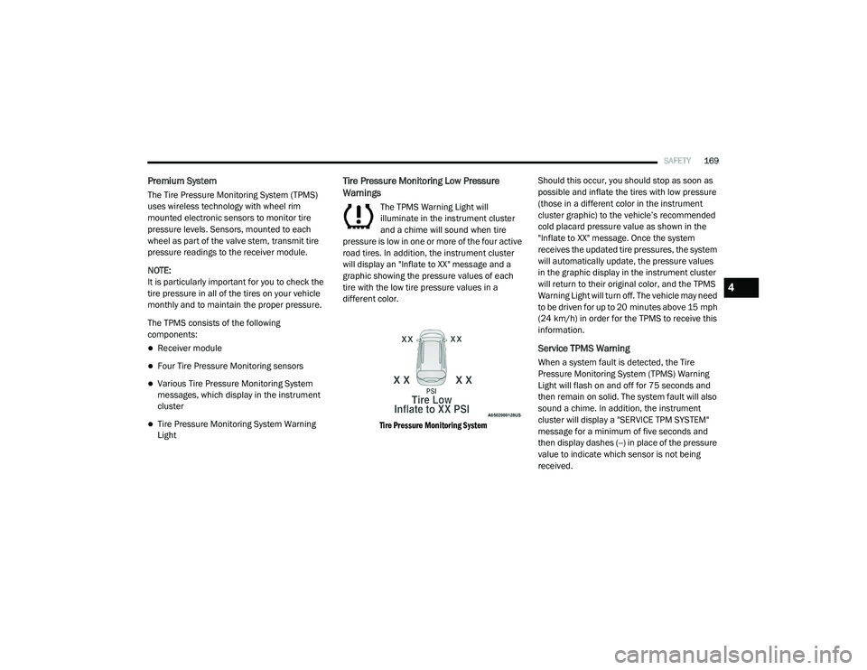
road tires. In addition, the instrument cluster
will display an "Inflate to XX" message and a
graphic showing the pressure values of each
tire with the low tire pressure values in a
different color.
Tire Pressure Monitoring System
Should this occur, you should stop as soon as
possible and inflate the tires with low pressure
(those in a different color in the instrument
cluster graphic) to the vehicle’s recommended
cold placard pressure value as shown in the
"Inflate to XX" message. Once the system
receives the updated tire pressures, the system
will automatically update, the pressure values
in the graphic display in the instrument cluster
will return to their original color, and the TPMS
Warning Light will turn off. The vehicle may need
to be driven for up to 20 minutes above 15 mph
(24 km/h) in order for the TPMS to receive this
information.
Service TPMS Warning
When a system fault is detected, the Tire
Pressure Monitoring System (TPMS) Warning
Light will flash on and off for 75 seconds and
then remain on solid. The system fault will also
sound a chime. In addition, the instrument
cluster will display a "SERVICE TPM SYSTEM"
message for a minimum of five seconds and
then display dashes (--) in place of the pressure
value to indicate which sensor is not being
received.
4
20_RU_OM_EN_US_t.book Page 169