HVAC CHRYSLER PACIFICA 2021 Owners Manual
[x] Cancel search | Manufacturer: CHRYSLER, Model Year: 2021, Model line: PACIFICA, Model: CHRYSLER PACIFICA 2021Pages: 401, PDF Size: 26.88 MB
Page 123 of 401

GETTING TO KNOW YOUR INSTRUMENT PANEL121
Speed Warning — If Equipped
Push and release the up or down arrow
button until Speed Warning is highlighted in the
instrument cluster display. Push and release the
OK button to enter Speed Warning. Use the
up or down arrow button to turn the Speed
Warning ON or OFF, then push and release the OK
button to confirm the selection. If the ON status is
selected, use the up or down arrow button
to set the desired speed, then push the OK button
to set the speed for the Speed Warning. A Speed
Warning telltale will illuminate in the instrument
cluster, with a number matching the set speed,
with a pop-up message to inform the driver that the
Speed Warning has been set to the desired speed.
Each time the set speed is exceeded, a single
chime will sound and a pop-up warning message
will display. If the set speed is exceeded more than
2 mph (3 km/h), a continuous chime will sound for
up to 10 seconds, or until the speed is no longer
exceeded. The telltale in the instrument cluster will
also change from white to yellow, and a pop-up
warning message will pop-up on the instrument
cluster display.
NOTE:Speed Warning is unavailable while KeySense is
in use.
BATTERY SAVER ON/BATTERY SAVER
M
ODE MESSAGE — ELECTRICAL LOAD
R
EDUCTION ACTIONS — IF EQUIPPED
This vehicle is equipped with an Intelligent Battery
Sensor (IBS) to perform additional monitoring of
the electrical system and status of the vehicle
battery.
In cases when the IBS detects charging system
failure, or the 12 Volt vehicle battery conditions are
deteriorating, electrical load reduction actions will
take place to extend the driving time and distance
of the vehicle. This is done by reducing power to or
turning off non-essential 12 Volt electrical loads.
Load reduction will be functional when the vehicle
propulsion system is active.
The vehicle may not be running depending on the
High Voltage (HV) battery State Of Charge (SOC) or
temperature. It will display a message if there is a
risk of battery depletion to the point where the
vehicle may stall due to lack of electrical supply, or
will not restart after the current drive cycle.
When 12 Volt load reduction is activated, the
message “Battery Saver On” or “Battery Saver
Mode” will appear in the instrument cluster
display. These messages indicate the vehicle battery has a
low state of charge and continues to lose electrical
charge at a rate that the charging system cannot
sustain.NOTE:
The charging system is independent from load
reduction. The charging system performs a diag
-
nostic on the charging system continuously.
If the Battery Charge Warning Light is on it may
indicate a problem with the charging system
Ú page 123.
The electrical loads that may be switched off (if
equipped), and vehicle functions which can be
effected by load reduction:
Heated Seat/Vented Seats/Heated Wheel
Heated/Cooled Cup Holders — If Equipped
Rear Defroster And Heated Mirrors
HVAC System
115 Volts AC Power Inverter System
Audio and Telematics System
3
21_RUP_OM_EN_USC_t.book Page 121
Page 124 of 401
122GETTING TO KNOW YOUR INSTRUMENT PANEL
Loss of the battery charge may indicate one or
more of the following conditions:
The charging system cannot deliver enough
electrical power to the vehicle system because
the electrical loads are larger than the capability
of charging system. The charging system is still
functioning properly.
Turning on all possible vehicle electrical loads
(e.g. HVAC to max settings, exterior and interior
lights, overloaded power outlets +12 Volts,
150W, USB ports) during certain driving condi -
tions (city driving, towing, frequent stopping).
Installing options like additional lights, upfitter
electrical accessories, audio systems, alarms
and similar devices.
Unusual driving cycles (short trips separated by
long parking periods).
The vehicle was parked for an extended period
of time (weeks, months).
The battery was recently replaced and was not
charged completely.
The battery was discharged by an electrical load
left on when the vehicle was parked.
The battery was used for an extended period
with the engine not running to supply radio,
lights, chargers, +12 Volt portable appliances
like vacuum cleaners, game consoles and
similar devices. What to do when an electrical load reduction
action message is present (“Battery Saver On” or
“Battery Saver Mode”)
During a trip:
Reduce power to unnecessary loads if possible:
Turn off redundant lights (interior or exte
-
rior)
Check what may be plugged in to power
outlets +12 Volts, 150W, USB ports
Check HVAC settings (blower, temperature)
Check the audio settings (volume)
After a trip:
Check if any aftermarket equipment was
installed (additional lights, upfitter electrical
accessories, audio systems, alarms) and review
specifications if any (load and Ignition Off Draw
currents).
Evaluate the latest driving cycles (distance,
driving time and parking time).
The vehicle should have service performed if
the message is still present during consecutive
trips and the evaluation of the vehicle and
driving pattern did not help to identify the cause.
TRIP COMPUTER
The Trip Computer is located in the instrument
cluster display. Push and release the up or
down arrow button until “Trip Info” is
highlighted in the instrument cluster display.
Navigate between Trip A or Trip B by using the
right and left arrow buttons.
For each trip the following information will be
displayed:
Trip A
Shows the total distance traveled for Trip A
since the last reset.
Shows the Average MPG for Trip A since the last
reset.
Shows the elapsed time traveled for Trip A since
the last reset. Elapsed time will increment when
the ignition switch is in the ON or START posi -
tion.
21_RUP_OM_EN_USC_t.book Page 122
Page 148 of 401
146STARTING AND OPERATING
HVAC is set to full defrost mode at a high blower
speed.
HVAC is set to MAX A/C.
Engine has not reached normal operating
temperature.
The transmission is not in a forward gear.
Hood is open.
Brake pedal is not pressed with sufficient pres -
sure.
Accelerator pedal input.
Engine temp is too high.
5 mph (8 km/h) threshold has not been
achieved from previous Autostop.
Steering angle is beyond threshold.
Vehicle at too high of an altitude.
Ambient temperature is beyond operating
range.
Stop/Start related system malfunction.
It may be possible for the vehicle to be driven
several times without the Stop/Start system going
into a STOP/START READY state under more
extreme conditions of the items listed above.
TO START THE ENGINE WHILE IN
A
UTOSTOP
While in a forward gear, the engine will start when
the brake pedal is released or the throttle pedal is
pressed. The transmission will automatically
re-engage upon engine restart.
Conditions That Will Cause The Engine To Start
Automatically While In Autostop:
The transmission selector is moved out of
DRIVE.
To maintain cabin temperature comfort.
HVAC is set to full defrost mode.
HVAC system temperature or fan speed is
manually adjusted.
Battery voltage drops too low. During this time a
message will display "Stop/Start Not Ready
Battery Charging".
Stop/Start OFF switch is pushed.
Stop/Start related system malfunction.
TO MANUALLY TURN OFF THE STOP/
S
TART SYSTEM
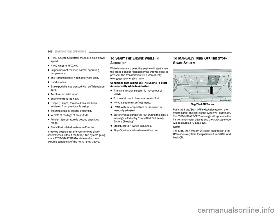
Stop/Start OFF Button
Push the Stop/Start OFF switch (located on the
switch bank). The light on the switch will illuminate.
The “STOP/START OFF” message will appear in the
instrument cluster display and the autostop mode
will be disabled Ú page 123.
NOTE:The Stop/Start system will reset itself back to the
ON mode every time the ignition is turned OFF and
back ON.
21_RUP_OM_EN_USC_t.book Page 146
Page 275 of 401
SAFETY273
Your vehicle may also be designed to perform any of
these other functions in response to the Enhanced
Accident Response System:
Turn off the Fuel Filter Heater, Turn off the HVAC
Blower Motor, Close the HVAC Circulation Door
Cut off battery power to the:
Engine
Electric Motor (if equipped)
Electric power steering
Brake booster
Electric park brake
Automatic transmission gear selector
Horn
Front wiper
Headlamp washer pump
NOTE:
After an accident, remember to cycle the ignition to
the STOP (OFF/LOCK) position and remove the key
from the ignition switch to avoid draining the battery.
Carefully check the vehicle for fuel leaks in the
engine compartment and on the ground near the
engine compartment and fuel tank before resetting
the system and starting the engine. If there are no
fuel leaks or damage to the vehicle electrical devices
(e.g. headlights) after an accident, reset the system
by following the procedure described below. If you
have any doubt, contact an authorized dealer.
Enhanced Accident Response System
Reset Procedure
If applicable, refer to the “Hybrid Supplement”
for additional information.
In order to reset the Enhanced Accident Response
System functions after an event, the ignition switch
must be changed from ignition START or ON/RUN
to ignition OFF. Carefully check the vehicle for fuel
leaks in the engine compartment and on the
ground near the engine compartment and fuel
tank before resetting the system and starting the
engine.
After an accident, if the vehicle will not start after
performing the reset procedure, the vehicle must
be towed to an authorized dealer to be inspected
and to have the Enhanced Accident Response
System reset.
6
21_RUP_OM_EN_USC_t.book Page 273
Page 351 of 401

SERVICING AND MAINTENANCE349
F25 –10 Amp RedHands Free Dr Mod / Active Grille
Shutter / Pwr Mirror / VRM
F26 40 Amp Green –Front HVAC Blower Motor
F27 25 Amp Clear –RR Slide Door Module-RT *
F28 –10 Amp RedDiagnostic Port / USB+(IP) / Video
USB Port / Overhead DVD Player (Aftermarket)
F29 ––Not Used
F30 –15 Amp BlueMedia HUB / Power Lumbar *
F31 ––Not Used
F32 20 Amp Blue –ECM
F33 30 Amp Pink –Power Liftgate Module *
F34 25 Amp Clear –RR Door Module-LT *
F35 25 Amp Clear –Sunroof *
F36 ––Not Used
F37 40 Amp Green –CBC / Exterior Lights
F38 60 Amp Yellow –Vacuum Cleaner *
F39 25 Amp Clear –Rear HVAC Blower Motor
F40 ––Not Used
F41 ––Not Used
F42 40 Amp Green –Folding Seat Module *
Cavity Cartridge Fuse Blade FuseDescription
* If Equipped
8
21_RUP_OM_EN_USC_t.book Page 349
Page 352 of 401
350SERVICING AND MAINTENANCE
F43 –20 Amp Yellow Fuel Pump Motor
F44 30 Amp Pink –CBC / Interior Lights
F45 30 Amp Pink –Power Inverter *
F46 30 Amp Pink –Driver Door Module
F47 30 Amp Pink –Passenger Door Module
F48 ––Not Used
F49 25 Amp Clear –RR Sliding Door Module-LT *
F50 25 Amp Clear –RR Door Module-RT *
F51 30 Amp Pink –Front Wiper
F52 30 Amp Pink –Brake Vacuum Pump
F53 ––Not Used
F54 40 Amp Green –ESP-ECU And Valves
F55 –15 Amp BlueRadio Frequency HUB / Keyless
Ignition System (KIN) / ESL / DVD
F56 –10 Amp RedFront and Rear HVAC Control Module
/ Occupant Classification Module
(OCM)/Electronic Steering Lock (ESL) / ESP / ESC
F57 ––Not Used
F58 –10 Amp RedDrive Train Control Mod / Power
Transfer Unit *
Cavity Cartridge Fuse Blade FuseDescription
* If Equipped
21_RUP_OM_EN_USC_t.book Page 350
Page 354 of 401
352SERVICING AND MAINTENANCE
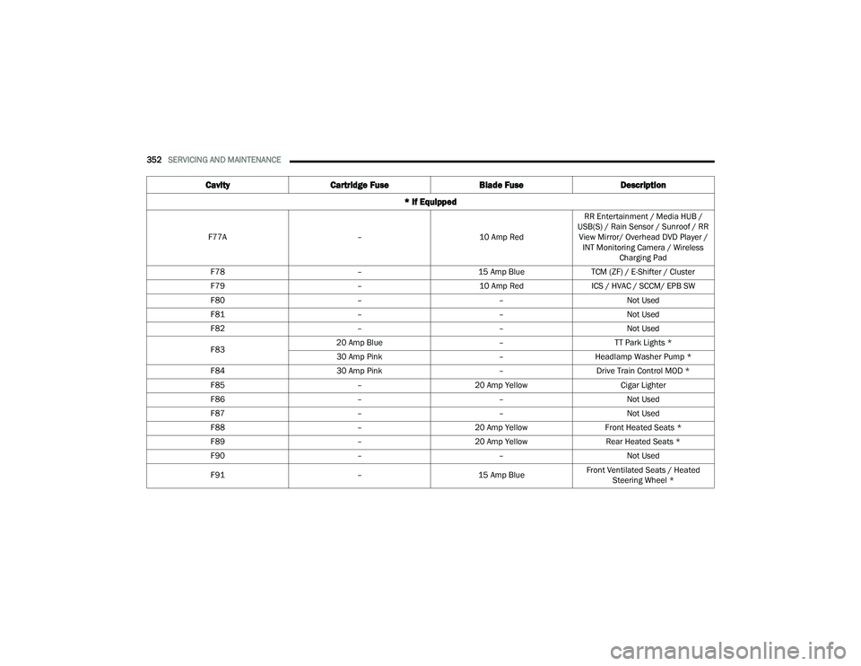
F77A –10 Amp RedRR Entertainment / Media HUB /
USB(S) / Rain Sensor / Sunroof / RR View Mirror/ Overhead DVD Player / INT Monitoring Camera / Wireless Charging Pad
F78 –15 Amp BlueTCM (ZF) / E-Shifter / Cluster
F79 –10 Amp RedICS / HVAC / SCCM/ EPB SW
F80 ––Not Used
F81 ––Not Used
F82 ––Not Used
F83 20 Amp Blue
–TT Park Lights *
30 Amp Pink –Headlamp Washer Pump *
F84 30 Amp Pink –Drive Train Control MOD *
F85 –20 Amp Yellow Cigar Lighter
F86 ––Not Used
F87 ––Not Used
F88 –20 Amp Yellow Front Heated Seats *
F89 –20 Amp Yellow Rear Heated Seats *
F90 ––Not Used
F91 –15 Amp BlueFront Ventilated Seats / Heated
Steering Wheel *
Cavity Cartridge Fuse Blade FuseDescription
* If Equipped
21_RUP_OM_EN_USC_t.book Page 352