hybrid CHRYSLER PACIFICA 2021 Owners Manual
[x] Cancel search | Manufacturer: CHRYSLER, Model Year: 2021, Model line: PACIFICA, Model: CHRYSLER PACIFICA 2021Pages: 401, PDF Size: 26.88 MB
Page 11 of 401
9
INTRODUCTION
Dear Customer,
Congratulations on the purchase of your new Chrysler vehicle. Be assured that it represents precision workmanship, distinctive styling, and high quality.
This Owner's Manual has been prepared with the assistance of service and engineering specialists to acquaint you with the operation and maintenance of your
vehicle. It is supplemented by customer-oriented documents. Within this information, you will find a description of the services that FCA US LLC offers to its
customers as well as the details of the terms and conditions for maintaining its validity. Please take the time to read all of these publications carefully before
driving your vehicle for the first time. Following the instructions, recommendations, tips, and important warnings in this manual will help ensure safe and
enjoyable operation of your vehicle.
This Owner's Manual describes all versions of this vehicle. Options and equipment dedicated to specific markets or versions are not expressly indicated in the
text. Therefore, you should only consider the information that is related to the trim level, engine, and version that you have purchased. Any content introduced
throughout the Owner's Information, which may or may not be applicable to your vehicle, will be identified with the wording “If Equipped” or, if applicable, refer
to the “Hybrid Supplement” for additional information. All data contained in this publication are intended to help you use your vehicle in the best possible way.
FCA US LLC aims at a constant improvement of the vehicles produced. For this reason, it reserves the right to make changes to the model described for technical
and/or commercial reasons. For further information, contact an authorized dealer.
When it comes to service, remember that authorized dealers know your Chrysler vehicle best, have factory-trained technicians, genuine Mopar® parts, and care
about your satisfaction.1
21_RUP_OM_EN_USC_t.book Page 9
Page 19 of 401
GETTING TO KNOW YOUR VEHICLE17
Start Up Display Features
Unique splash screen graphic
Telltale illuminated
After unique splash screen, and after stored
messages are cycled, then start-up KeySense
messages (Range & Max Speed) are displayed
The following features are always enabled when
this key is in use:
Entertainment audio muted if front occupied
seat belts are not fastened
Consistent seat belt unfastened chime
Maximum radio volume limited to 15 out of 39
Daytime Running Lights
Headlights On With Wipers
Rain Sensing Wipers
Automatic High Beams
SENTRY KEY
The Sentry Key Immobilizer system prevents
unauthorized vehicle operation by disabling the
engine. The system does not need to be armed or
activated. Operation is automatic, regardless of
whether the vehicle is locked or unlocked. The system uses a key fob, keyless push button
ignition and a Radio Frequency (RF) receiver to
prevent unauthorized vehicle operation. Therefore,
only key fobs that are programmed to the vehicle
can be used to start and operate the vehicle. The
system cannot reprogram a key fob obtained from
another vehicle.
After placing the ignition switch in the ON/RUN
position, the Vehicle Security Light will turn on for
three seconds for a bulb check. If the light remains
on after the bulb check, it indicates that there is a
problem with the electronics. In addition, if the light
begins to flash after the bulb check, it indicates
that someone attempted to start the engine with
an invalid key fob. In the event that a valid key fob
is used to start the engine but there is an issue
with the vehicle electronics, the engine will start
and shut off after two seconds.
If the Vehicle Security Light turns on during normal
vehicle operation (vehicle running for longer than
10 seconds), it indicates that there is a fault in the
electronics. Should this occur, have the vehicle
serviced as soon as possible by an authorized
dealer.
All of the key fobs provided with your new vehicle
have been programmed to the vehicle electronics
Ú
page 387.
IGNITION SWITCH
KEYLESS ENTER ‘N GO™ IGNITION
If applicable, refer to the “Hybrid Supplement”
for additional information.
This feature allows the driver to operate the
ignition switch with the push of a button as long as
the key fob is in the passenger compartment.
The START/STOP ignition button has four
operating positions; three of which are labeled and
will illuminate when in position. The three positions
are OFF, ACC, and ON/RUN. The fourth position is
START. During START, RUN will illuminate.
CAUTION!
The Sentry Key Immobilizer system is not
compatible with some aftermarket Remote Start
systems. Use of these systems may result in
vehicle starting problems and loss of security
protection.
2
21_RUP_OM_EN_USC_t.book Page 17
Page 21 of 401
GETTING TO KNOW YOUR VEHICLE19
NOTE:
The key fob may not be detected by the vehicle
Keyless Enter ‘n Go™ system if it is located next
to a mobile phone, laptop or other electronic
device; these devices may block the key fob’s
wireless signal and prevent the Keyless Enter ‘n
Go™ system from starting the vehicle.
For the proper engine starting procedure, see
Úpage 132.
REMOTE START — IF EQUIPPED
If applicable, refer to the “Hybrid Supplement”
for additional information.
This system uses the key fob to start the
engine conveniently from outside the
vehicle while still maintaining security.
The system has a range of 328 ft
(100 m).
Remote Start is used to defrost windows in cold
weather and to reach a comfortable climate in all
ambient conditions before the customer enters the
vehicle.
NOTE:Obstructions between the vehicle and key fob may
reduce this range Ú page 387.
HOW TO USE REMOTE START
If applicable, refer to the “Hybrid Supplement”
for additional information.
Push and release the Remote Start button on the
key fob twice within five seconds. The vehicle
doors will lock, the parking lights will flash, and the
horn will chirp twice (if programmed). Then, the
engine will start, and the vehicle will remain in the
Remote Start mode for a 15 minute cycle.
Pushing the Remote Start button a third time shuts
the engine off. To drive the vehicle, push the unlock button, and
place the ignition in the ON/RUN position.
NOTE:
With Remote Start, the engine will only run for
15 minutes.
Remote Start can only be used twice.
If an engine fault is present or fuel level is
low, the vehicle will start and then shut down in
10 seconds.
The parking lights will turn on and remain on
during Remote Start mode.
For security, power window and power sunroof
operation (if equipped) are disabled when the
vehicle is in the Remote Start mode.
The ignition must be placed in the ON/RUN posi
-
tion before the Remote Start sequence can be
repeated for a third cycle.
WARNING!
Do not start or run an engine in a closed
garage or confined area. Exhaust gas contains
Carbon Monoxide (CO) which is odorless and
colorless. Carbon Monoxide is poisonous and
can cause serious injury or death when
inhaled.
Keep key fobs away from children. Operation
of the Remote Start system, windows, door
locks or other controls could cause serious
injury or death.
2
21_RUP_OM_EN_USC_t.book Page 19
Page 22 of 401
20GETTING TO KNOW YOUR VEHICLE
All of the following conditions must be met before
the engine will Remote Start:
Gear selector in PARK
Doors closed
Hood closed
Liftgate closed
Hazard switch off
Brake switch inactive (brake pedal not pressed)
Battery at an acceptable charge level
PANIC button not pushed
System not disabled from previous Remote
Start event
Vehicle Security system indicator flashing
Ignition in OFF position
Fuel level meets minimum requirement
Vehicle Security system is not signaling an
intrusion
Malfunction Indicator Light (MIL) is not
illuminated
TO EXIT REMOTE START MODE
If applicable, refer to the “Hybrid Supplement”
for additional information.
To drive the vehicle after starting the Remote Start
system, either push and release the unlock button
on the key fob to unlock the doors, or unlock the
vehicle using Keyless Enter ‘n Go™ — Passive Entry
via the door handles, and disarm the Vehicle
Security system (if equipped). Then, prior to the
end of the 15 minute cycle, push and release the
START/STOP ignition button. The Remote Start system will turn the engine off if
the Remote Start button is pushed again, or if the
engine is allowed to run for the entire 15 minute
cycle. Once the ignition is placed in the ON/RUN
position, the climate controls will resume the
previously set operations (temperature, blower
control, etc.).
NOTE:
For vehicles equipped with the Keyless
Enter ‘n Go™ — Passive Entry feature, the
message “Remote Start Active — Push Start
Button” will show in the instrument cluster
display until you push the START/STOP ignition
button.
To avoid unintentional shutdowns, the system
will disable for two seconds after receiving a
valid Remote Start request.
REMOTE START FRONT DEFROST
A
CTIVATION — IF EQUIPPED
When Remote Start is active, and the outside
ambient temperature is 40°F (4.5°C) or below, the
system will automatically activate front defrost for
15 minutes or less. The time is dependent on the
ambient temperature. Once the timer expires, the
system will automatically adjust the settings
depending on ambient conditions. See “Remote
Start Comfort Systems — If Equipped” in the next
section for detailed operation.
WARNING!
Do not start or run an engine in a closed
garage or confined area. Exhaust gas contains
Carbon Monoxide (CO) which is odorless and
colorless. Carbon Monoxide is poisonous and
can cause serious injury or death when
inhaled.
Keep key fobs away from children. Operation
of the Remote Start system, windows, door
locks or other controls could cause serious
injury or death.
21_RUP_OM_EN_USC_t.book Page 20
Page 39 of 401

GETTING TO KNOW YOUR VEHICLE37
The release strap is located on the front of the
seat, near the floor. To remove the seat, pull the
release strap to release the rear latches. The seat
assembly can now be removed from the vehicle by
moving it in a rearward direction from the detent
positions in the floor.
Release Strap
NOTE:Seat can be removed easier with one outboard
seat stowed in the load floor.
To reinstall the seat, align the seat into the detent
positions on the floor. Tilt seat rearward to lock the
seatback into its original position.
In Floor Detent Guides
Fold-Flat — Quad Seats
If applicable, refer to the “Hybrid Supplement”
for additional information.
To fold the seat, lift the recliner lever to the full
upward position and push the seatback forward
until it rests on the seat cushion.
Fold-Flat Seat Recline Lever
NOTE:
The seatback may lock into the fold-flat position.
Use the recline lever to unlock the seatback.
If equipped with Stow ‘n Go seating: when
returning the seat to the original position, the
headrest must be folded back to the original
position.
WARNING!
If not properly latched, the seat could become
loose. Personal injuries could result.
2
21_RUP_OM_EN_USC_t.book Page 37
Page 40 of 401
38GETTING TO KNOW YOUR VEHICLE
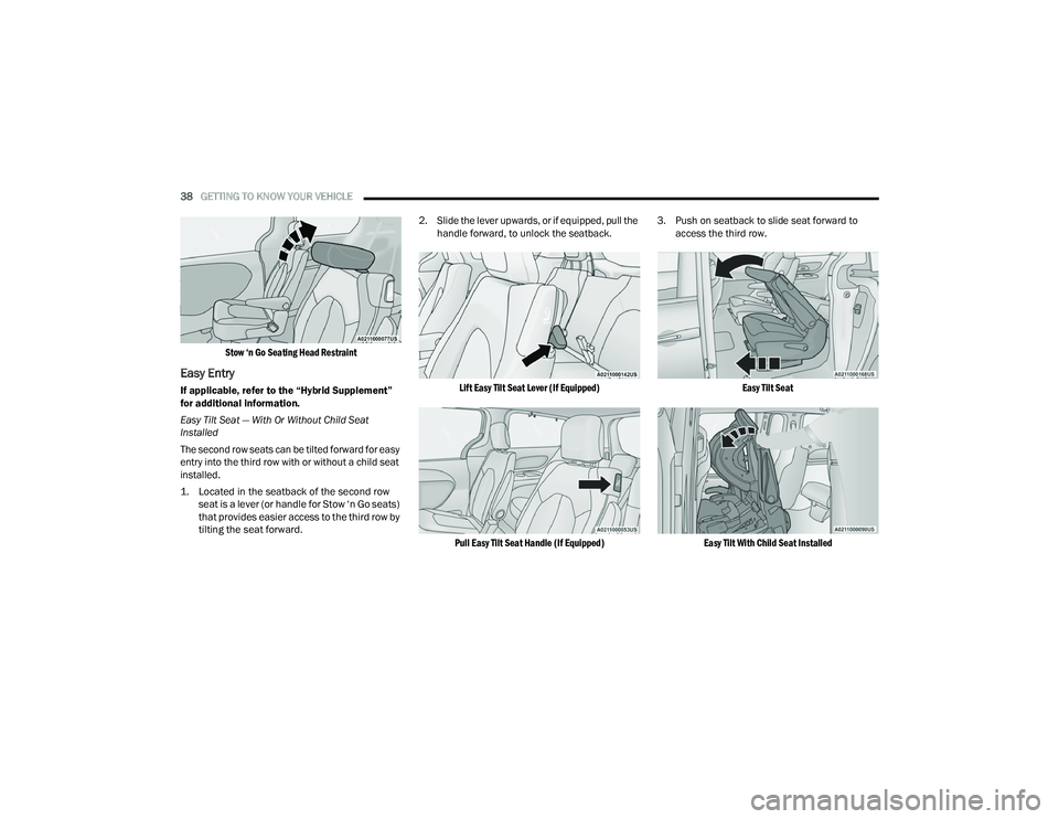
Stow ‘n Go Seating Head Restraint
Easy Entry
If applicable, refer to the “Hybrid Supplement”
for additional information.
Easy Tilt Seat — With Or Without Child Seat
Installed
The second row seats can be tilted forward for easy
entry into the third row with or without a child seat
installed.
1. Located in the seatback of the second row seat is a lever (or handle for Stow ‘n Go seats)
that provides easier access to the third row by
tilting the seat forward.
2. Slide the lever upwards, or if equipped, pull the
handle forward, to unlock the seatback.
Lift Easy Tilt Seat Lever (If Equipped)
Pull Easy Tilt Seat Handle (If Equipped)
3. Push on seatback to slide seat forward to
access the third row.
Easy Tilt Seat
Easy Tilt With Child Seat Installed
21_RUP_OM_EN_USC_t.book Page 38
Page 99 of 401
GETTING TO KNOW YOUR VEHICLE97
HOOD
OPENING
If applicable, refer to the “Hybrid Supplement”
for additional information.
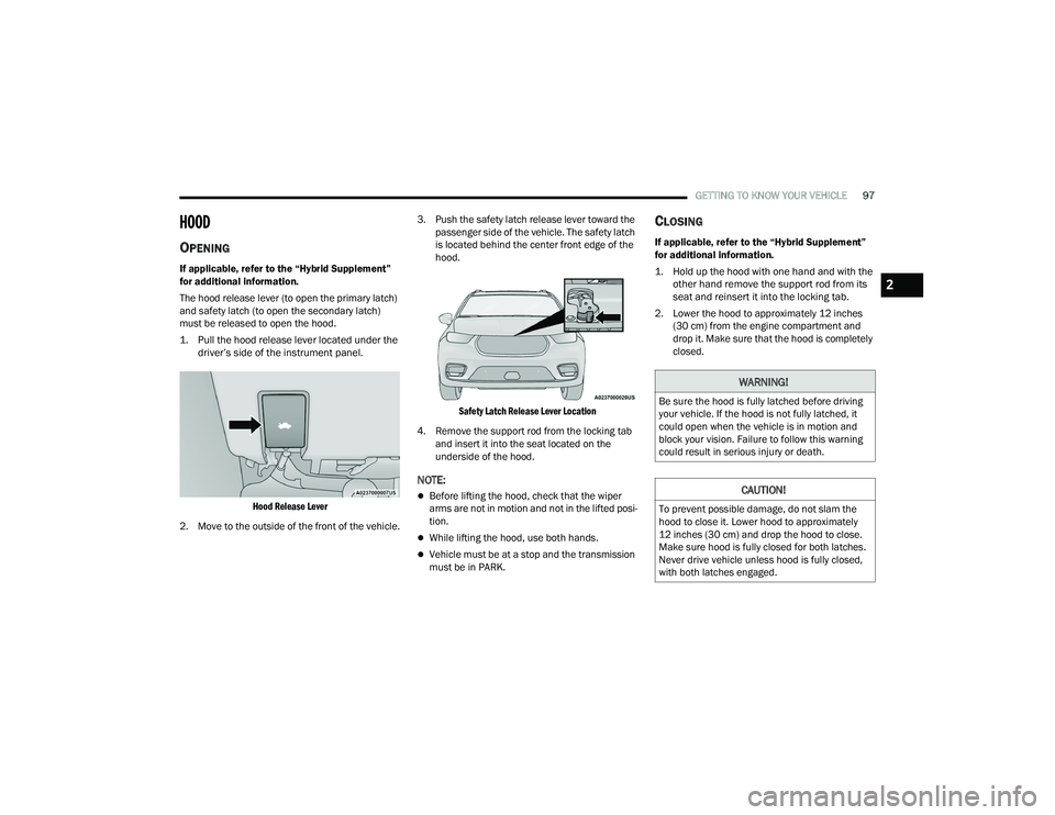
The hood release lever (to open the primary latch)
and safety latch (to open the secondary latch)
must be released to open the hood.
1. Pull the hood release lever located under the
driver’s side of the instrument panel.
Hood Release Lever
2. Move to the outside of the front of the vehicle. 3. Push the safety latch release lever toward the
passenger side of the vehicle. The safety latch
is located behind the center front edge of the
hood.
Safety Latch Release Lever Location
4. Remove the support rod from the locking tab and insert it into the seat located on the
underside of the hood.
NOTE:
Before lifting the hood, check that the wiper
arms are not in motion and not in the lifted posi -
tion.
While lifting the hood, use both hands.
Vehicle must be at a stop and the transmission
must be in PARK.
CLOSING
If applicable, refer to the “Hybrid Supplement”
for additional information.
1. Hold up the hood with one hand and with the other hand remove the support rod from its
seat and reinsert it into the locking tab.
2. Lower the hood to approximately 12 inches (30 cm) from the engine compartment and
drop it. Make sure that the hood is completely
closed.
WARNING!
Be sure the hood is fully latched before driving
your vehicle. If the hood is not fully latched, it
could open when the vehicle is in motion and
block your vision. Failure to follow this warning
could result in serious injury or death.
CAUTION!
To prevent possible damage, do not slam the
hood to close it. Lower hood to approximately
12 inches (30 cm) and drop the hood to close.
Make sure hood is fully closed for both latches.
Never drive vehicle unless hood is fully closed,
with both latches engaged.
2
21_RUP_OM_EN_USC_t.book Page 97
Page 179 of 401
STARTING AND OPERATING177
Loading
The actual total weight and the weight of the front
and rear of your vehicle at the ground can best be
determined by weighing it when it is loaded and
ready for operation.
The entire vehicle should first be weighed on a
commercial scale to ensure that the GVWR has not
been exceeded. The weight on the front and rear of
the vehicle should then be determined separately
to be sure that the load is properly distributed over
the front and rear axle. Weighing the vehicle may
show that the GAWR of either the front or rear axles
has been exceeded but the total load is within the
specified GVWR. If so, weight must be shifted from
front to rear or rear to front as appropriate until the
specified weight limitations are met. Store the
heavier items down low and be sure that the
weight is distributed equally. Stow all loose items
securely before driving.
Improper weight distributions can have an adverse
effect on the way your vehicle steers and handles
and the way the brakes operate.
TRAILER TOWING
NOTE:Trailer towing is not permitted for the Plug-in
Hybrid Electric Vehicle (PHEV).
In this section you will find safety tips and
information on limits to the type of towing you can
reasonably do with your vehicle. Before towing a
trailer, carefully review this information to tow your
load as efficiently and safely as possible.
To maintain the New Vehicle Limited Warranty
coverage, follow the requirements and
recommendations in this manual concerning
vehicles used for trailer towing.
COMMON TOWING DEFINITIONS
The following trailer towing related definitions will
assist you in understanding the following
information:
Gross Vehicle Weight Rating (GVWR)
GVWR is the total allowable weight of your vehicle.
This includes driver, passengers, cargo and tongue
weight. The total load must be limited so that you
do not exceed the GVWR Úpage 176.
Gross Trailer Weight (GTW)
GTW is the weight of the trailer plus the weight of
all cargo, consumables and equipment
(permanent or temporary) loaded in or on the
trailer in its "loaded and ready for operation"
condition.
The recommended way to measure GTW is to put
your fully loaded trailer on a vehicle scale. The
entire weight of the trailer must be supported by
the scale.
CAUTION!
Do not load your vehicle any heavier than the
GVWR or the maximum front and rear GAWR. If
you do, parts on your vehicle can break, or it can
change the way your vehicle handles. This could
cause you to lose control. Also overloading can
shorten the life of your vehicle.
4
21_RUP_OM_EN_USC_t.book Page 177
Page 260 of 401
258SAFETY
Seat Belts And Pregnant Women
Seat Belts And Pregnant Women
Seat belts must be worn by all occupants including
pregnant women: the risk of injury in the event of
an accident is reduced for the mother and the
unborn child if they are wearing a seat belt.
Position the lap belt snug and low below the
abdomen and across the strong bones of the hips.
Place the shoulder belt across the chest and away
from the neck. Never place the shoulder belt
behind the back or under the arm.
Seat Belt Pretensioner
The front outboard seat belt system is equipped
with pretensioning devices that are designed to
remove slack from the seat belt in the event of a
collision. These devices may improve the
performance of the seat belt by removing slack
from the seat belt early in a collision. Pretensioners
work for all size occupants, including those in child
restraints.
NOTE:These devices are not a substitute for proper seat
belt placement by the occupant. The seat belt still
must be worn snugly and positioned properly.
The pretensioners are triggered by the Occupant
Restraint Controller (ORC). Like the air bags, the
pretensioners are single use items. A deployed
pretensioner or a deployed air bag must be
replaced immediately.
Energy Management Feature
The front outboard seat belt system is equipped
with an Energy Management feature that may help
further reduce the risk of injury in the event of a
collision. The seat belt system has a retractor
assembly that is designed to release webbing in a
controlled manner.
Switchable Automatic Locking Retractors
(ALR)
If applicable, refer to the “Hybrid Supplement”
for additional information.
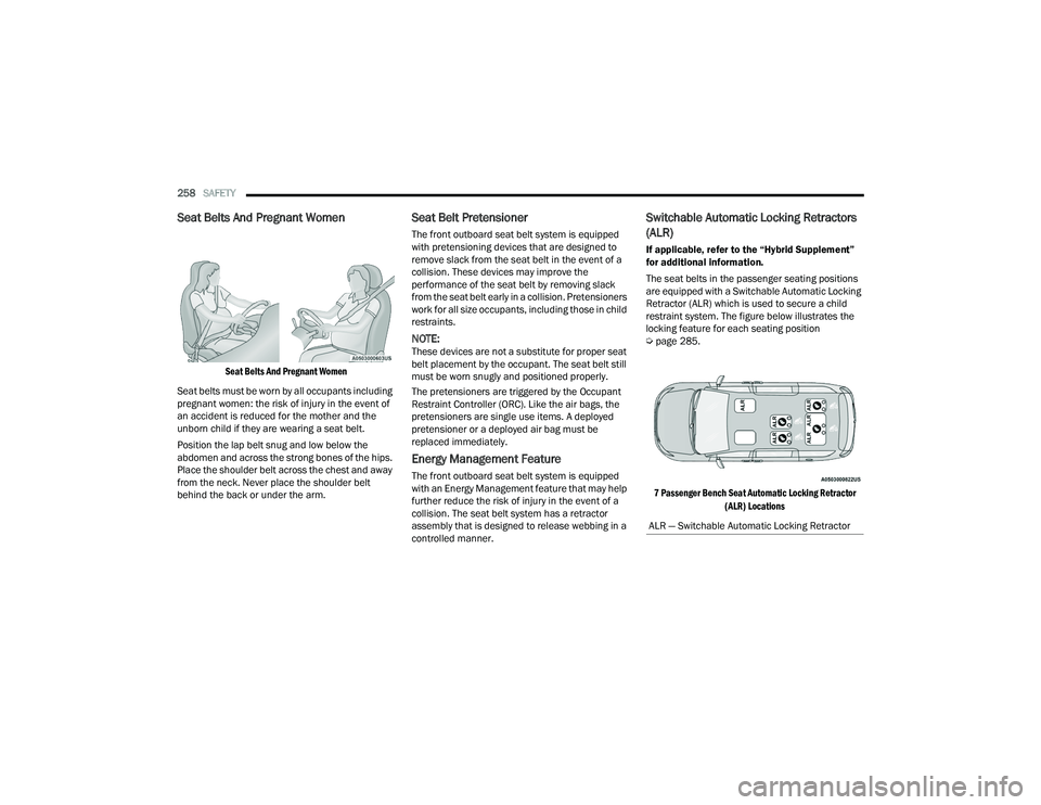
The seat belts in the passenger seating positions
are equipped with a Switchable Automatic Locking
Retractor (ALR) which is used to secure a child
restraint system. The figure below illustrates the
locking feature for each seating position
Ú page 285.
7 Passenger Bench Seat Automatic Locking Retractor (ALR) Locations
ALR — Switchable Automatic Locking Retractor
21_RUP_OM_EN_USC_t.book Page 258
Page 275 of 401
SAFETY273
Your vehicle may also be designed to perform any of
these other functions in response to the Enhanced
Accident Response System:
Turn off the Fuel Filter Heater, Turn off the HVAC
Blower Motor, Close the HVAC Circulation Door
Cut off battery power to the:
Engine
Electric Motor (if equipped)
Electric power steering
Brake booster
Electric park brake
Automatic transmission gear selector
Horn
Front wiper
Headlamp washer pump
NOTE:
After an accident, remember to cycle the ignition to
the STOP (OFF/LOCK) position and remove the key
from the ignition switch to avoid draining the battery.
Carefully check the vehicle for fuel leaks in the
engine compartment and on the ground near the
engine compartment and fuel tank before resetting
the system and starting the engine. If there are no
fuel leaks or damage to the vehicle electrical devices
(e.g. headlights) after an accident, reset the system
by following the procedure described below. If you
have any doubt, contact an authorized dealer.
Enhanced Accident Response System
Reset Procedure
If applicable, refer to the “Hybrid Supplement”
for additional information.
In order to reset the Enhanced Accident Response
System functions after an event, the ignition switch
must be changed from ignition START or ON/RUN
to ignition OFF. Carefully check the vehicle for fuel
leaks in the engine compartment and on the
ground near the engine compartment and fuel
tank before resetting the system and starting the
engine.
After an accident, if the vehicle will not start after
performing the reset procedure, the vehicle must
be towed to an authorized dealer to be inspected
and to have the Enhanced Accident Response
System reset.
6
21_RUP_OM_EN_USC_t.book Page 273