keyless CHRYSLER PACIFICA 2022 User Guide
[x] Cancel search | Manufacturer: CHRYSLER, Model Year: 2022, Model line: PACIFICA, Model: CHRYSLER PACIFICA 2022Pages: 384, PDF Size: 23.92 MB
Page 25 of 384
GETTING TO KNOW YOUR VEHICLE23
Cycle the vehicle ignition system out of the
OFF position.
For vehicles equipped with Keyless
Enter ‘n Go™ — Passive Entry, push the
START/STOP ignition button (requires at
least one valid key fob in the vehicle).
NOTE:
The driver's door key cylinder and the liftgate
button on the key fob cannot arm or disarm the
Vehicle Security system.
The Vehicle Security system remains armed
during power liftgate entry. Pushing the liftgate
button will not disarm the Vehicle Security
system. If someone enters the vehicle through
the liftgate and opens any door, the alarm will
sound.
When the Vehicle Security system is armed, the
interior power door lock switches will not unlock
the doors.
The Vehicle Security system is designed to protect
your vehicle. However, you can create conditions
where the system will give you a false alarm. If one
of the previously described arming sequences has
occurred, the Vehicle Security system will arm
regardless of whether you are in the vehicle or not.
If you remain in the vehicle and open a door, the
alarm will sound. If this occurs, disarm the Vehicle
Security system. If the Vehicle Security system is armed and the
battery becomes disconnected, the Vehicle
Security system will remain armed when the
battery is reconnected; the exterior lights will flash,
and the horn will sound. If this occurs, disarm the
Vehicle Security system.
REARMING OF THE SYSTEM
If something triggers the alarm and no action is
taken to disarm it, the Vehicle Security system will
turn the horn off after a 29 second cycle (with five
seconds between cycles and up to 8 cycles if the
trigger remains active) and then rearm itself.
SECURITY SYSTEM MANUAL OVERRIDE
The Vehicle Security system will not arm if you lock
the doors using the manual door lock.
DOORS
MANUAL DOOR LOCKS — IF EQUIPPED
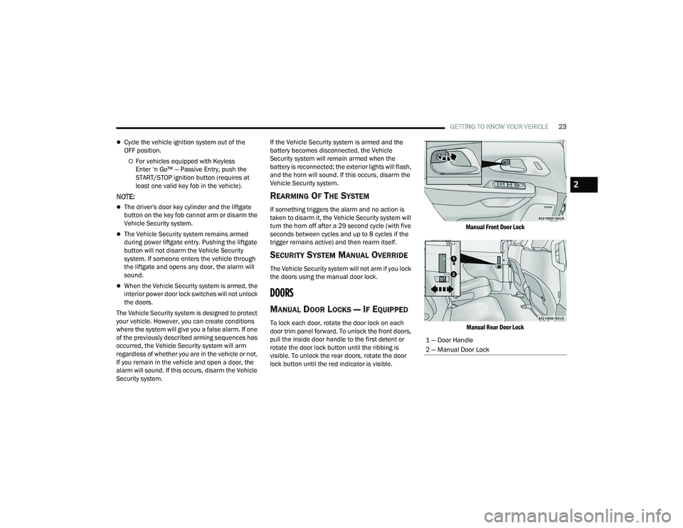
To lock each door, rotate the door lock on each
door trim panel forward. To unlock the front doors,
pull the inside door handle to the first detent or
rotate the door lock button until the ribbing is
visible. To unlock the rear doors, rotate the door
lock button until the red indicator is visible.
Manual Front Door Lock
Manual Rear Door Lock
1 — Door Handle
2 — Manual Door Lock
2
22_RUP_OM_EN_USC_t.book Page 23
Page 26 of 384
24GETTING TO KNOW YOUR VEHICLE
(Continued)
If the door lock is in the locked position (no ribbing
is visible) when you shut the door, the door will
lock. Therefore, make sure the key fob is not inside
the vehicle before closing the door.
NOTE:The manual door locks will not lock or unlock the
liftgate.
POWER DOOR LOCKS — IF EQUIPPED
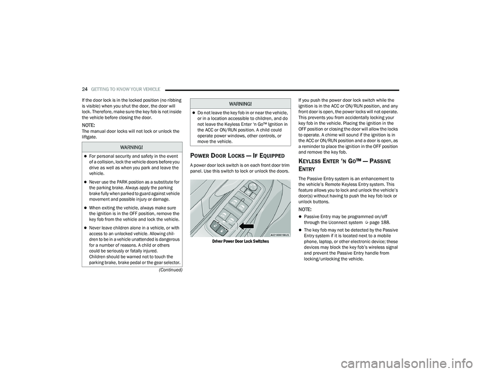
A power door lock switch is on each front door trim
panel. Use this switch to lock or unlock the doors.
Driver Power Door Lock Switches
If you push the power door lock switch while the
ignition is in the ACC or ON/RUN position, and any
front door is open, the power locks will not operate.
This prevents you from accidentally locking your
key fob in the vehicle. Placing the ignition in the
OFF position or closing the door will allow the locks
to operate. A chime will sound if the ignition is in
the ACC or ON/RUN position and a door is open, as
a reminder to place the ignition in the OFF position
and remove the key fob.KEYLESS ENTER ‘N GO™ — PASSIVE
E
NTRY
The Passive Entry system is an enhancement to
the vehicle’s Remote Keyless Entry system. This
feature allows you to lock and unlock the vehicle’s
door(s) without having to push the key fob lock or
unlock buttons.
NOTE:
Passive Entry may be programmed on/off
through the Uconnect system Ú page 188.
The key fob may not be detected by the Passive
Entry system if it is located next to a mobile
phone, laptop, or other electronic device; these
devices may block the key fob’s wireless signal
and prevent the Passive Entry handle from
locking/unlocking the vehicle.
WARNING!
For personal security and safety in the event
of a collision, lock the vehicle doors before you
drive as well as when you park and leave the
vehicle.
Never use the PARK position as a substitute for
the parking brake. Always apply the parking
brake fully when parked to guard against vehicle
movement and possible injury or damage.
When exiting the vehicle, always make sure
the ignition is in the OFF position, remove the
key fob from the vehicle and lock the vehicle.
Never leave children alone in a vehicle, or with
access to an unlocked vehicle. Allowing chil -
dren to be in a vehicle unattended is dangerous
for a number of reasons. A child or others
could be seriously or fatally injured.
Children should be warned not to touch the
parking brake, brake pedal or the gear selector.
Do not leave the key fob in or near the vehicle,
or in a location accessible to children, and do
not leave the Keyless Enter ‘n Go™ Ignition in
the ACC or ON/RUN position. A child could
operate power windows, other controls, or
move the vehicle.
WARNING!
22_RUP_OM_EN_USC_t.book Page 24
Page 65 of 384
GETTING TO KNOW YOUR VEHICLE63
2. Push the programmed HomeLink® button to confirm that the garage door opener motor
operates. If the garage door opener motor
does not operate, repeat the steps from the
beginning.
PROGRAMMING HOMELINK® TO A
M
ISCELLANEOUS DEVICE
The procedure on how to program HomeLink® to a
miscellaneous device follows the same procedure
as programming to a garage door opener
Ú page 62. Be sure to determine if the device has
a rolling code, or non-rolling code before beginning
the programming process.
NOTE:Canadian Radio Frequency (RF) laws require trans -
mitter signals to time-out (or quit) after several
seconds of transmission, which may not be long
enough for HomeLink® to pick up the signal during
programming. Similar to this Canadian law, some
U.S. gate operators are designed to time-out in the
same manner. The procedure may need to be
performed multiple times to successfully pair the
device to your HomeLink® buttons.
REPROGRAMMING A SINGLE
H
OMELINK® BUTTON
To reprogram a single HomeLink® button that has
been previously trained, without erasing all the
channels, proceed as follows. Be sure to
determine whether the new device you want to
program the HomeLink® button to has a rolling
code, or non-rolling code.
1. Place the ignition in the ON/RUN position,
without starting the engine.
2. Push and hold the desired HomeLink® button until the HomeLink® indicator light begins to
flash after 20 seconds. Do not release the
button.
3. Without releasing the button , proceed with
Step 2 in “Programming HomeLink® To A
Garage Door Opener” and follow all remaining
steps.
CANADIAN/GATE OPERATOR
P
ROGRAMMING
For programming transmitters in Canada/United
States that require the transmitter signals to
“time-out” after several seconds of transmission:
Canadian Radio Frequency (RF) laws require
transmitter signals to time-out (or quit) after
several seconds of transmission, which may not be
long enough for HomeLink® to pick up the signal
during programming. Similar to this Canadian law,
some U.S. gate operators are designed to time-out
in the same manner.
It may be helpful to unplug the device during the
cycling process to prevent possible overheating of
the garage door or gate motor.
1. Place the ignition in the ON/RUN position.
NOTE:For vehicles equipped with Keyless Enter ‘n Go™,
place the ignition in the RUN position. Make sure
while programming HomeLink® with the engine on
that your vehicle is outside of your garage, or that
the garage door remains open at all times.
2. Place the hand-held transmitter 1 to 3 inches
(3 to 8 cm) away from the HomeLink® button
you wish to program while keeping the
HomeLink® indicator light in view.
WARNING!
Your motorized door or gate will open and
close while you are programming the universal
transmitter. Do not program the transmitter if
people or pets are in the path of the door or
gate.
Do not run your vehicle in a closed garage or
confined area while programming the trans -
mitter. Exhaust gas from your vehicle contains
Carbon Monoxide (CO) which is odorless and
colorless. Carbon Monoxide is poisonous
when inhaled and can cause you and others to
be severely injured or killed.
2
22_RUP_OM_EN_USC_t.book Page 63
Page 71 of 384
GETTING TO KNOW YOUR VEHICLE69
INTERIOR LIGHTS
INTERIOR COURTESY LIGHTS
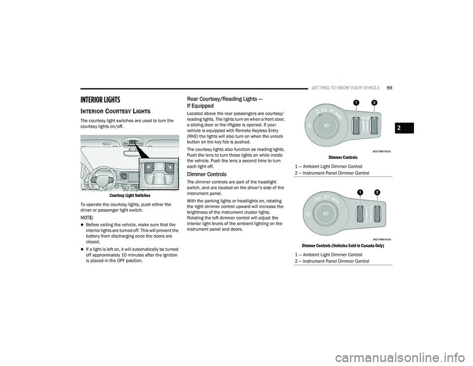
The courtesy light switches are used to turn the
courtesy lights on/off.
Courtesy Light Switches
To operate the courtesy lights, push either the
driver or passenger light switch.
NOTE:
Before exiting the vehicle, make sure that the
interior lights are turned off. This will prevent the
battery from discharging once the doors are
closed.
If a light is left on, it will automatically be turned
off approximately 10 minutes after the ignition
is placed in the OFF position.
Rear Courtesy/Reading Lights —
If Equipped
Located above the rear passengers are courtesy/
reading lights. The lights turn on when a front door,
a sliding door or the liftgate is opened. If your
vehicle is equipped with Remote Keyless Entry
(RKE) the lights will also turn on when the unlock
button on the key fob is pushed.
The courtesy lights also function as reading lights.
Push the lens to turn these lights on while inside
the vehicle. Push the lens a second time to turn
each light off.
Dimmer Controls
The dimmer controls are part of the headlight
switch, and are located on the driver’s side of the
instrument panel.
With the parking lights or headlights on, rotating
the right dimmer control upward will increase the
brightness of the instrument cluster lights.
Rotating the left dimmer control will adjust the
interior light levels of the ambient lighting on the
instrument panel and doors.
Dimmer Controls
Dimmer Controls (Vehicles Sold In Canada Only)
1 — Ambient Light Dimmer Control
2 — Instrument Panel Dimmer Control
1 — Ambient Light Dimmer Control
2 — Instrument Panel Dimmer Control
2
22_RUP_OM_EN_USC_t.book Page 69
Page 96 of 384
94GETTING TO KNOW YOUR VEHICLE
(Continued)
WIND BUFFETING
Wind buffeting can be described as the perception
of pressure on the ears or a helicopter-type sound
in the ears. Your vehicle may exhibit wind buffeting
with the windows down, or the sunroof (if
equipped) in certain open or partially open
positions. This is a normal occurrence and can be
minimized. If the buffeting occurs with the rear
windows open, open the front and rear windows
together to minimize the buffeting. If the buffeting
occurs with the sunroof open, adjust the sunroof
opening to minimize the buffeting or open any
window.
PANORAMIC SUNROOF — IF EQUIPPED
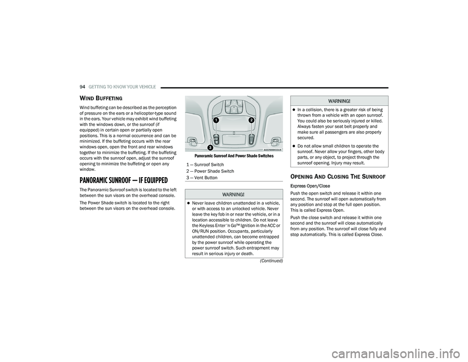
The Panoramic Sunroof switch is located to the left
between the sun visors on the overhead console.
The Power Shade switch is located to the right
between the sun visors on the overhead console.
Panoramic Sunroof And Power Shade Switches
OPENING AND CLOSING THE SUNROOF
Express Open/Close
Push the open switch and release it within one
second. The sunroof will open automatically from
any position and stop at the full open position.
This is called Express Open.
Push the close switch and release it within one
second and the sunroof will close automatically
from any position. The sunroof will close fully and
stop automatically. This is called Express Close.
1 — Sunroof Switch
2 — Power Shade Switch
3 — Vent Button
WARNING!
Never leave children unattended in a vehicle,
or with access to an unlocked vehicle. Never
leave the key fob in or near the vehicle, or in a
location accessible to children. Do not leave
the Keyless Enter ‘n Go™ Ignition in the ACC or
ON/RUN position. Occupants, particularly
unattended children, can become entrapped
by the power sunroof while operating the
power sunroof switch. Such entrapment may
result in serious injury or death.
In a collision, there is a greater risk of being
thrown from a vehicle with an open sunroof.
You could also be seriously injured or killed.
Always fasten your seat belt properly and
make sure all passengers are also properly
secured.
Do not allow small children to operate the
sunroof. Never allow your fingers, other body
parts, or any object, to project through the
sunroof opening. Injury may result.
WARNING!
22_RUP_OM_EN_USC_t.book Page 94
Page 103 of 384

GETTING TO KNOW YOUR VEHICLE101
(Continued)
IMPORTANT SAFETY INSTRUCTIONS
Read all instructions before using. When using
your vacuum, basic precautions should be
followed, including the following:
WARNING!
Never leave children alone in a vehicle, or
with access to an unlocked vehicle. Allowing
children to be in a vehicle unattended is
dangerous for a number of reasons. A child or
others could be seriously or fatally injured.
Children should be warned not to touch the
parking brake, brake pedal or the gear
selector.
Do not leave the key fob in or near the vehicle,
or in a location accessible to children, and do
not leave the Keyless Enter ‘n Go™ Ignition in
either the ACC position, or engine running
(ON), unless you are using the vacuum
system. Be aware a child could operate power
windows, other controls, or move the vehicle
when the vacuum system is in use. ALWAYS
push ignition button to place ignition in the
OFF position when finished using the vacuum
system.
WARNING!
To reduce the risk of fire, serious injury or death:
Do not use vacuum while vehicle is
in motion or while driving.
Do not vacuum wet surfaces or any liquids.
Do not use to vacuum up anything outside of
the vehicle.
Do not vacuum any flammable
liquids, such as gasoline, or use
around explosive vapors. Vapors
from flammable liquids may form an
explosive mixture with air and can be ignited
by heat, sparks, or flames. Vapors may travel
to a source of ignition and explode.
Do not vacuum anything that is burning or
smoking, such as cigarettes, matches, or hot
ashes/embers.
Do not allow to be used as a toy. Close atten -
tion is necessary when used by or near chil -
dren.
Do not leave the vacuum running while unat -
tended.
Use only as described in this manual. Use only
attachments provided with your vehicle.
Do not put any object into openings. Do not
use with any opening blocked; keep free of
dust, lint, hair, and anything that may reduce
air flow.
Do not vacuum toxic material such as chlorine
bleach, ammonia, drain cleaner, etc.
Do not vacuum hard or sharp objects such as
glass, nails, screws, coins, etc.
Keep hair, loose clothing, fingers, and all parts
of body away from openings and moving parts.
Only use with filter in place. Periodically check
that the filter is in place and in good condition.
WARNING!
This equipment incorporates parts such as
switches, motors, or the like that tend to
produce arcs or sparks that can cause an
explosion. When using your vacuum near
gasoline-dispensing equipment or service
stations, park vehicle at least 20 ft (6 m) away
from the exterior enclosure of any dispensing
pump. The vacuum is mounted more than
18 inches (45 cm) above ground level in your
vehicle.
WARNING!
2
22_RUP_OM_EN_USC_t.book Page 101
Page 133 of 384
131
(Continued)
STARTING AND OPERATING
STARTING THE ENGINE
Before starting your vehicle, adjust your seat,
adjust both inside and outside mirrors, and fasten
your seat belts.Start the engine with the gear selector in the
NEUTRAL (N) or PARK (P) position. Apply the brake
before shifting to any driving range.
NORMAL STARTING
To Turn On The Engine Using ENGINE START/STOP
Button
1. The transmission must be in PARK or NEUTRAL.
2. Press and hold the brake pedal while pushing the ENGINE START/STOP button once.
3. The system starts the vehicle. If the vehicle fails to start, the starter will disengage
automatically after 10 seconds.
4. If you wish to stop the cranking of the engine prior to the engine starting, push the button
again. ENGINE START/STOP Button Functions — With
Driver’s Foot Off The Brake Pedal (In PARK Or
NEUTRAL Position)
The ENGINE START/STOP button operates similar
to an ignition switch. It has three positions; OFF,
ACC, and ON/RUN. To change the ignition positions
without starting the vehicle and to use the
accessories, follow these steps:
Start with the ignition in the OFF position.
Push the ENGINE START/STOP button once to
place the ignition to the ACC position (instru
-
ment cluster will display “ACC”).
Push the ENGINE START/STOP button a second
time to place the ignition to the ON/RUN posi -
tion (instrument cluster will display “ON/RUN”).
Push the ENGINE START/STOP button a third
time to return the ignition to the OFF position
(instrument cluster will display “OFF”).
NOTE:Only press one pedal at a time while driving the
vehicle. Torque performance of the vehicle could
be reduced if both pedals are pressed at the same
time. If pressure is detected on both pedals simul -
taneously, a warning message will display in the
instrument cluster Ú page 113.
WARNING!
When exiting the vehicle, always remove the
key fob from the vehicle and lock your vehicle.
Never leave children alone in a vehicle, or with
access to an unlocked vehicle.
Allowing children to be in a vehicle unattended
is dangerous for a number of reasons. A child
or others could be seriously or fatally injured.
Children should be warned not to touch the
parking brake, brake pedal or the transmis -
sion gear selector.
Do not leave the key fob in or near the vehicle,
or in a location accessible to children, and do
not leave the ignition of a vehicle equipped
with Keyless Enter ‘n Go™ in the ACC or ON/
RUN position. A child could operate power
windows, other controls, or move the vehicle.
Do not leave children or animals inside parked
vehicles in hot weather. Interior heat buildup
may cause serious injury or death.
WARNING!
4
22_RUP_OM_EN_USC_t.book Page 131
Page 206 of 384
204MULTIMEDIA
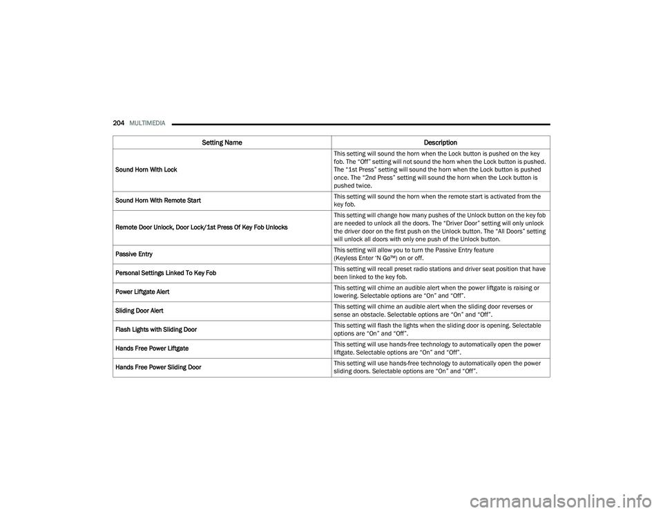
Sound Horn With Lock This setting will sound the horn when the Lock button is pushed on the key
fob. The “Off” setting will not sound the horn when the Lock button is pushed.
The “1st Press” setting will sound the horn when the Lock button is pushed
once. The “2nd Press” setting will sound the horn when the Lock button is
pushed twice.
Sound Horn With Remote Start This setting will sound the horn when the remote start is activated from the
key fob.
Remote Door Unlock, Door Lock/1st Press Of Key Fob Unlocks This setting will change how many pushes of the Unlock button on the key fob
are needed to unlock all the doors. The “Driver Door” setting will only unlock
the driver door on the first push on the Unlock button. The “All Doors” setting
will unlock all doors with only one push of the Unlock button.
Passive Entry This setting will allow you to turn the Passive Entry feature
(Keyless Enter ‘N Go™) on or off.
Personal Settings Linked To Key Fob This setting will recall preset radio stations and driver seat position that have
been linked to the key fob.
Power Liftgate Alert This setting will chime an audible alert when the power liftgate is raising or
lowering. Selectable options are “On” and “Off”.
Sliding Door Alert This setting will chime an audible alert when the sliding door reverses or
sense an obstacle. Selectable options are “On” and “Off”.
Flash Lights with Sliding Door This setting will flash the lights when the sliding door is opening. Selectable
options are “On” and “Off”.
Hands Free Power Liftgate This setting will use hands-free technology to automatically open the power
liftgate. Selectable options are “On” and “Off”.
Hands Free Power Sliding Door This setting will use hands-free technology to automatically open the power
sliding doors. Selectable options are “On” and “Off”.
Setting Name
Description
22_RUP_OM_EN_USC_t.book Page 204
Page 335 of 384
SERVICING AND MAINTENANCE333
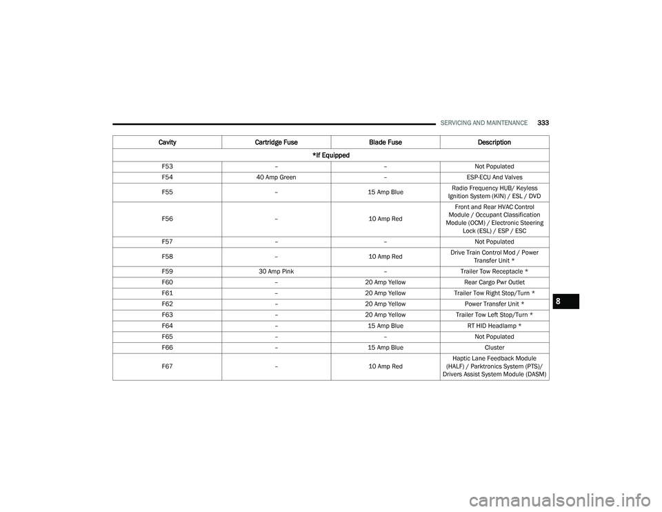
F53 ––Not Populated
F54 40 Amp Green –ESP-ECU And Valves
F55 –15 Amp BlueRadio Frequency HUB/ Keyless
Ignition System (KIN) / ESL / DVD
F56 –10 Amp RedFront and Rear HVAC Control
Module / Occupant Classification
Module (OCM) / Electronic Steering Lock (ESL) / ESP / ESC
F57 ––Not Populated
F58 –10 Amp RedDrive Train Control Mod / Power
Transfer Unit *
F59 30 Amp Pink –Trailer Tow Receptacle *
F60 –20 Amp Yellow Rear Cargo Pwr Outlet
F61 –20 Amp YellowTrailer Tow Right Stop/Turn *
F62 –20 Amp Yellow Power Transfer Unit *
F63 –20 Amp Yellow Trailer Tow Left Stop/Turn *
F64 –15 Amp Blue RT HID Headlamp *
F65 ––Not Populated
F66 –15 Amp Blue Cluster
F67 –10 Amp RedHaptic Lane Feedback Module
(HALF) / Parktronics System (PTS)/
Drivers Assist System Module (DASM)
Cavity Cartridge Fuse Blade FuseDescription
*If Equipped
8
22_RUP_OM_EN_USC_t.book Page 333
Page 374 of 384
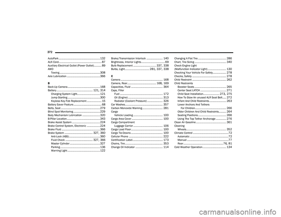
372 AutoPark
........................................................ 132AUX Cord.......................................................... 87Auxiliary Electrical Outlet (Power Outlet).......... 89AWD Towing....................................................... 308Axle Lubrication............................................. 366
B
Back-Up Camera............................................ 168Battery................................................. 121, 314Charging System Light............................... 121Jump Starting............................................ 300Keyless Key Fob Replacement.................... 15Battery Saver Feature...................................... 68Belts, Seat..................................................... 279Blind Spot Monitoring.................................... 229Body Mechanism Lubrication........................ 320B-Pillar Location............................................. 343Brake Assist System...................................... 224Brake Control System, Electronic.................. 224Brake Fluid.................................................... 366Brake System...................................... 327, 360Anti-Lock (ABS).......................................... 360Fluid Check..................................... 327, 366Master Cylinder......................................... 327Parking...................................................... 136Warning Light............................................ 122
Brake/Transmission Interlock...................... 140Brightness, Interior Lights................................ 69Bulb Replacement............................... 337, 338Bulbs, Light................................. 281, 337, 338
C
Camera......................................................... 168Camera, Rear....................................... 168, 169Capacities, Fluid........................................... 364Caps, FillerFuel.......................................................... 172Oil (Engine)............................................... 313Radiator (Coolant Pressure)..................... 326Car Washes................................................... 357Carbon Monoxide Warning............................ 281CargoVehicle Loading........................................ 100Cargo Area Cover.......................................... 100Cargo CompartmentLuggage Carrier........................................ 106Cargo Load Floor........................................... 100Cargo Tie-Downs........................................... 100Cellular Phone.............................................. 222Certification Label......................................... 173Chains, Tire................................................... 353Change Oil Indicator..................................... 114
Changing A Flat Tire...................................... 286Chart, Tire Sizing........................................... 340Check Engine Light
(Malfunction Indicator Light)......................... 130Checking Your Vehicle For Safety.................. 278Checks, Safety.............................................. 278Child Restraint.............................................. 262Child RestraintsBooster Seats........................................... 265Center Seat LATCH................................... 271Child Seat Installation...................... 273, 275How To Stow An unused ALR Seat Belt..... 272Infant And Child Restraints....................... 263Lower Anchors And Tethers For Children.......................................... 266Older Children And Child Restraints.......... 264Seating Positions...................................... 266Using The Top Tether Anchorage.............. 276Clean Air Gasoline......................................... 361CleaningWheels...................................................... 352Climate Control................................................72Automatic....................................................72Manual........................................................77Rear......................................................76, 81Cold Weather Operation................................ 134
22_RUP_OM_EN_USC_t.book Page 372