ESP CHRYSLER PACIFICA 2023 Owner's Guide
[x] Cancel search | Manufacturer: CHRYSLER, Model Year: 2023, Model line: PACIFICA, Model: CHRYSLER PACIFICA 2023Pages: 328, PDF Size: 16.37 MB
Page 183 of 328
MULTIMEDIA181
14.Play/Pause Button ‖ — Begin/resume or pause disc
play.
15. Channel +/- — Push the up or down arrow button on
the Channel button to browse channels available in
Fire TV.
16. Recent — Push to access recently viewed content on
Fire TV.
17. Gear/Settings — Push to bring up setting options for
Fire TV.
18. App 2 — Push to launch App 2.
19. Vehicle Button — Push to activate the Vehicle menu.
Replacing the Voice Remote with Alexa
Batteries
Each Voice Remote with Alexa requires two AAA batteries
for operation.
To replace the batteries:
1. Locate the battery compartment on the back of the
Voice Remote with Alexa, then slide the battery
cover downward.
2. Remove the old batteries and follow battery recycling procedures for your area.
3. Install new batteries, making sure to orient them according to the polarity diagram shown inside the
battery compartment.
4. Slide the battery compartment cover back on.
REAR SEAT ENTERTAINMENT WITH FIRE
TV
BUILT-IN STREAMING (USING THE
F
RONT RADIO AND REAR SCREENS)
Access Using Launch Source
To access Rear Seat Entertainment with Fire TV built-in
from the front radio, press the Media tab located on the
bottom menu bar. Then select the Rear Seat option
located on the top menu bar. Select “Launch Source”, and
then under “Inputs” select “Fire TV Home”.
Access Using Browse Media
Selecting “Browse Media” on the front radio screen will
give access to different media within Rear Seat
Entertainment with Fire TV built-in.
These options will be in the top menu of “Browse Media”
and include:
Fire TV — Selecting “Fire TV” will show streaming
options for categories and to select apps. This option
will be selectable on the left slider menu in “Browse
Media”. While in “Browse Media” under Fire TV, it will
display recent activity under “Recent”. This will display
recent videos viewed from Fire TV and recent down -
loads as well.
USB Video — Under “USB Videos”, videos will appear
that are options with a USB device connected to Rear
Seat Entertainment with Fire TV built-in.
USB Music — Under “USB Music”, music will appear
that are options with a USB device connected to Rear
Seat Entertainment with Fire TV built-in. Access Using the Voice Remote with Alexa and Rear
Screens
Rear passengers will be able to access some options for
streaming by pressing the “Prime Video”, “App 1”, or
“App 2” button on the Voice Remote with Alexa. Selecting
one of those buttons on the Voice Remote with Alexa will
take you to the home page for that respective streaming
service. Turning on either of the rear screens will launch
Fire TV. By default, the rear screens will always launch in
Fire TV. More streaming options can be selected on the
Fire TV home page.
Fire TV
Fire TV is your source for online streaming with Rear Seat
Entertainment with Fire TV built-in.
NOTE:A data source needs to be connected to the system for
streaming to be accessible. This can be set up when Fire
TV is turned on for the first time from the rear screens.
Some of these options can be an in-vehicle 4G Wi-Fi hot
spot, capable Wi-Fi hot spot from a mobile device, or Wi-Fi
from an outside source like a home or a garage.
To access Fire TV on the front screen, select “Launch
Source” on the front touchscreen, rear seat screen, and
then “Fire TV Home” under “Inputs”.
Viewing from the front radio screen mirrors or controls the
Fire TV experience from one of the rear Fire TV displays.
The menu bar for Fire TV will have the options for “Home”,
“Find”, “Library”, “Brand”, and “Live”.
Below the menu bar will be streaming options linked to
your Prime account like “Prime Video”.
5
23_RUP_OM_EN_USC_t.book Page 181
Page 190 of 328
188SAFETY
ELECTRONIC BRAKE CONTROL (EBC)
S
YSTEM
Your vehicle is equipped with an advanced Electronic
Brake Control (EBC) system. This system includes
Anti-Lock Brake System (ABS), Brake Assist System (BAS),
Electronic Brake Force Distribution (EBD), Electronic Roll
Mitigation (ERM), Electronic Stability Control (ESC), Hill
Start Assist (HSA), and Traction Control System
(TCS).These systems work together to enhance both
vehicle stability and control in various driving conditions.
Your vehicle may also be equipped with Dynamic Steering
Torque (DST), Ready Alert Braking (RAB), Rain Brake
Support (RBS) and Trailer Sway Control (TSC).
Brake Assist System (BAS)
The BAS is designed to optimize the vehicle’s braking
capability during emergency braking maneuvers. The
system detects an emergency braking situation by sensing
the rate and amount of brake application and then applies
optimum pressure to the brakes. This can help reduce
braking distances. The BAS complements the Anti-Lock
Brake System (ABS). Applying the brakes very quickly
results in the best BAS assistance. To receive the benefit
of the system, you must apply continuous braking
pressure during the stopping sequence (do not “pump”
the brakes). Do not reduce brake pedal pressure unless
braking is no longer desired. Once the brake pedal is
released, the BAS is deactivated.
Brake System Warning Light
The red Brake System Warning Light will turn on when the
ignition is placed in the ON/RUN mode and may stay on for
as long as four seconds.
If the Brake System Warning Light remains on or comes on
while driving, it indicates that the brake system is not
functioning properly and that immediate service is
required. If the Brake System Warning Light does not
come on when the ignition is placed in the ON/RUN mode,
have the light repaired as soon as possible.
Dynamic Steering Torque (DST)
DST is a feature of the ESC and Electric Power Steering
(EPS) modules that provides torque at the steering wheel
for certain driving conditions in which the ESC module is
detecting vehicle instability. The torque that the steering
wheel receives is only meant to help the driver realize
optimal steering behavior in order to reach/maintain vehicle stability. The only notification the driver receives
that the feature is active, is the torque applied to the
steering wheel.
NOTE:The DST feature is only meant to help the driver realize the
correct course of action through small torques on the
steering wheel, which means the effectiveness of the DST
feature is highly dependent on the driver’s sensitivity and
overall reaction to the applied torque. It is very important
to realize that this feature will not steer the vehicle,
meaning the driver is still responsible for steering the
vehicle.
Electronic Brake Force Distribution (EBD)
The EBD function manages the distribution of the braking
torque between the front and rear axles by limiting braking
pressure to the rear axle. This is done to prevent overslip
of the rear wheels to avoid vehicle instability, and to
prevent the rear axle from entering the Anti-Lock Brake
System (ABS) before the front axle.
Electronic Roll Mitigation (ERM)
ERM anticipates the potential for wheel lift by monitoring
the driver’s steering wheel input and the speed of the
vehicle. When ERM determines that the rate of change of
the steering wheel angle and vehicle’s speed are
sufficient to potentially cause wheel lift, it then applies the
appropriate brake and may also reduce engine power to
lessen the chance that wheel lift will occur. ERM can only
reduce the chance of wheel lift occurring during severe or
evasive driving maneuvers; it cannot prevent wheel lift
due to other factors, such as road conditions, leaving the
roadway, striking objects or other vehicles.
WARNING!
The Brake Assist System (BAS) cannot prevent the
natural laws of physics from acting on the vehicle, nor
can it increase the traction afforded by prevailing road
conditions. BAS cannot prevent collisions, including
those resulting from excessive speed in turns, driving
on very slippery surfaces, or hydroplaning. The
capabilities of a BAS-equipped vehicle must never be
exploited in a reckless or dangerous manner, which
could jeopardize the user's safety or the safety of
others.
23_RUP_OM_EN_USC_t.book Page 188
Page 191 of 328
SAFETY189
Electronic Stability Control (ESC)
ESC enhances directional control and stability of the
vehicle under various driving conditions. ESC corrects for
oversteering or understeering of the vehicle by applying
the brake of the appropriate wheel(s) to assist in
counteracting these conditions. Engine power may also be
reduced to help the vehicle maintain the desired path.
Oversteer — when the vehicle is turning more than
appropriate for the steering wheel position.
Understeer — when the vehicle is turning less than
appropriate for the steering wheel position.
ESC uses sensors in the vehicle to determine the vehicle
path intended by the driver and compares it to the actual
path of the vehicle. When the actual path does not match
the intended path, ESC applies the brake of the
appropriate wheel to assist in counteracting the oversteer
or understeer condition.
The ESC Activation/Malfunction Indicator Light located in
the instrument cluster will start to flash as soon as the ESC
system becomes active. The ESC Activation/Malfunction
Indicator Light also flashes when the TCS is active. If the ESC Activation/Malfunction Indicator Light begins to flash
during acceleration, ease up on the accelerator and apply
as little throttle as possible. Be sure to adapt your speed
and driving to the prevailing road conditions.
ESC Operating Modes
Depending upon model and mode of operation, the ESC
system may have multiple operating modes.
ESC On
This is the normal operating mode for the ESC. Whenever
the vehicle is started, the ESC system will be in this mode.
This mode should be used for most driving conditions.
Alternate ESC modes should only be used for specific
reasons as noted in the following paragraphs.
Partial Off
This mode may be useful if the vehicle becomes stuck.
This mode may modify TCS and ESC thresholds for
activation, which allows for more wheel spin than normally
allowed.
To enter the “Partial Off” mode, momentarily push the ESC
OFF button and the ESC OFF Indicator Light will illuminate.
To turn the ESC on again, momentarily push the ESC OFF
button and the ESC OFF Indicator Light will turn off.
NOTE:When driving with snow chains, or when starting off in
deep snow, sand, or gravel, it may be desirable to allow
more wheel spin. This can be accomplished by momen
-
tarily pushing the ESC OFF button to enter partial mode
“Partial Off” mode. Once the situation requiring “Partial
Off” mode is overcome, turn ESC back on by momentarily
pushing the ESC OFF button. This may be done while the
vehicle is in motion.
WARNING!
Many factors, such as vehicle loading, road conditions
and driving conditions, influence the chance that wheel
lift or rollover may occur. ERM cannot prevent all wheel
lift or rollovers, especially those that involve leaving the
roadway or striking objects or other vehicles. The
capabilities of an ERM-equipped vehicle must never be
exploited in a reckless or dangerous manner which could
jeopardize the user's safety or the safety of others.
WARNING!
Electronic Stability Control (ESC) cannot prevent the
natural laws of physics from acting on the vehicle, nor
can it increase the traction afforded by prevailing road
conditions. ESC cannot prevent accidents, including
those resulting from excessive speed in turns, driving
on very slippery surfaces, or hydroplaning. ESC also
cannot prevent accidents resulting from loss of vehicle
control due to inappropriate driver input for the condi -
tions. Only a safe, attentive, and skillful driver can
prevent accidents. The capabilities of an ESC
equipped vehicle must never be exploited in a reckless
or dangerous manner which could jeopardize the
user’s safety or the safety of others.
Vehicle modifications, or failure to properly maintain
your vehicle, may change the handling characteris -
tics of your vehicle, and may negatively affect the
performance of the ESC system. Changes to the
steering system, suspension, braking system, tire
type and size or wheel size may adversely affect ESC
performance. Improperly inflated and unevenly worn
tires may also degrade ESC performance. Any vehicle
modification or poor vehicle maintenance that
reduces the effectiveness of the ESC system can
increase the risk of loss of vehicle control, vehicle
rollover, personal injury and death.
6
23_RUP_OM_EN_USC_t.book Page 189
Page 192 of 328
190SAFETY
ESC Activation/Malfunction Indicator Light
And ESC OFF Indicator Light
The ESC Activation/Malfunction Indicator Light
in the instrument cluster will come on when the
ignition is placed in the ON/RUN mode. It
should go out with the engine running. If the
ESC Activation/Malfunction Indicator Light comes on
continuously with the engine running, a malfunction has
been detected in the ESC system. If this light remains on
after several ignition cycles, and the vehicle has been
driven several miles (kilometers) at speeds greater than
30 mph (48 km/h), see an authorized dealer as soon as possible to have the problem diagnosed and corrected. The ESC Activation/Malfunction Indicator Light starts to
flash as soon as the tires lose traction and the ESC system
becomes active. The ESC Activation/Malfunction Indicator
Light also flashes when TCS is active. If the ESC
Activation/Malfunction Indicator Light begins to flash
during acceleration, ease up on the accelerator and apply
as little throttle as possible. Be sure to adapt your speed
and driving to the prevailing road conditions.
The ESC OFF Indicator Light indicates that the
Electronic Stability Control (ESC) is in a reduced
mode.
NOTE:
The ESC Activation/Malfunction Indicator Light and the
ESC OFF Indicator Light come on momentarily each
time the ignition is placed in the ON/RUN position.
Each time the ignition is placed in the ON/RUN posi -
tion, the ESC system will be on even if it was turned off
previously.
The ESC system will make buzzing or clicking sounds
when it is active. This is normal; the sounds will stop
when ESC becomes inactive following the maneuver
that caused the ESC activation.
Hill Start Assist (HSA)
HSA is designed to mitigate roll back from a complete stop
while on an incline. If the driver releases the brake while
stopped on an incline, HSA will continue to hold the brake
pressure for a short period. If the driver does not apply the
throttle before this time expires, the system will release
brake pressure and the vehicle will roll down the hill as
normal. The following conditions must be met in order for HSA to
activate:
The feature must be enabled.
The vehicle must be stopped.
The parking brake must be off.
The driver door must be closed.
The vehicle must be on a sufficient grade.
The gear selection must match vehicle uphill direction
(i.e., vehicle facing uphill is in forward gear; vehicle
backing uphill is in REVERSE (R) gear).
HSA will work in REVERSE gear and all forward gears.
The system will not activate if the transmission is in
PARK (P) or NEUTRAL (N).
WARNING!
When in “Partial Off” mode, the TCS functionality of
ESC (except for the limited slip feature described in
the TCS section) has been disabled and the ESC OFF
Indicator Light will be illuminated. When in “Partial
Off” mode, the engine power reduction feature of
TCS is disabled, and the enhanced vehicle stability
offered by the ESC system is reduced.
Trailer Sway Control (TSC) is disabled when the ESC
system is in the “Partial Off” mode.
WARNING!
There may be situations where the Hill Start Assist
(HSA) will not activate and slight rolling may occur, such
as on minor hills or with a loaded vehicle, or while
pulling a trailer. HSA is not a substitute for active driving
involvement. It is always the driver’s responsibility to be
attentive to distance to other vehicles, people, and
objects, and most importantly brake operation to
ensure safe operation of the vehicle under all road
conditions. Your complete attention is always required
while driving to maintain safe control of your vehicle.
Failure to follow these warnings can result in a collision
or serious personal injury.
23_RUP_OM_EN_USC_t.book Page 190
Page 196 of 328
194SAFETY
The BSM system is designed not to issue an alert on
stationary objects such as guardrails, posts, walls, foliage,
berms, snow banks, car washes, etc. However,
occasionally the system may alert on such objects. This is
normal operation and your vehicle does not require
service.
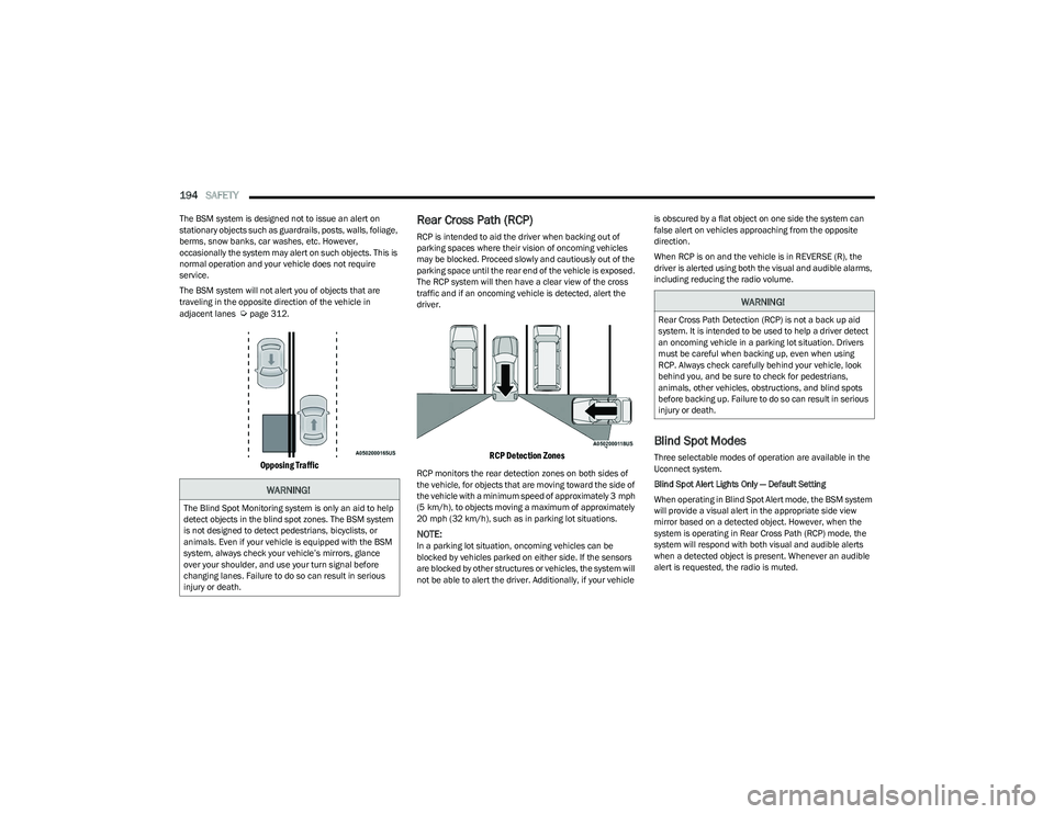
The BSM system will not alert you of objects that are
traveling in the opposite direction of the vehicle in
adjacent lanes
Úpage 312.
Opposing Traffic
Rear Cross Path (RCP)
RCP is intended to aid the driver when backing out of
parking spaces where their vision of oncoming vehicles
may be blocked. Proceed slowly and cautiously out of the
parking space until the rear end of the vehicle is exposed.
The RCP system will then have a clear view of the cross
traffic and if an oncoming vehicle is detected, alert the
driver.
RCP Detection Zones
RCP monitors the rear detection zones on both sides of
the vehicle, for objects that are moving toward the side of
the vehicle with a minimum speed of approximately 3 mph
(5 km/h), to objects moving a maximum of approximately
20 mph (32 km/h), such as in parking lot situations.
NOTE:In a parking lot situation, oncoming vehicles can be
blocked by vehicles parked on either side. If the sensors
are blocked by other structures or vehicles, the system will
not be able to alert the driver. Additionally, if your vehicle is obscured by a flat object on one side the system can
false alert on vehicles approaching from the opposite
direction.
When RCP is on and the vehicle is in REVERSE (R), the
driver is alerted using both the visual and audible alarms,
including reducing the radio volume.
Blind Spot Modes
Three selectable modes of operation are available in the
Uconnect system.
Blind Spot Alert Lights Only — Default Setting
When operating in Blind Spot Alert mode, the BSM system
will provide a visual alert in the appropriate side view
mirror based on a detected object. However, when the
system is operating in Rear Cross Path (RCP) mode, the
system will respond with both visual and audible alerts
when a detected object is present. Whenever an audible
alert is requested, the radio is muted.
WARNING!
The Blind Spot Monitoring system is only an aid to help
detect objects in the blind spot zones. The BSM system
is not designed to detect pedestrians, bicyclists, or
animals. Even if your vehicle is equipped with the BSM
system, always check your vehicle’s mirrors, glance
over your shoulder, and use your turn signal before
changing lanes. Failure to do so can result in serious
injury or death.
WARNING!
Rear Cross Path Detection (RCP) is not a back up aid
system. It is intended to be used to help a driver detect
an oncoming vehicle in a parking lot situation. Drivers
must be careful when backing up, even when using
RCP. Always check carefully behind your vehicle, look
behind you, and be sure to check for pedestrians,
animals, other vehicles, obstructions, and blind spots
before backing up. Failure to do so can result in serious
injury or death.
23_RUP_OM_EN_USC_t.book Page 194
Page 197 of 328
SAFETY195
Blind Spot Alert Lights/Chime
When operating in Blind Spot Alert Lights/Chime mode,
the BSM system will provide a visual alert in the
appropriate side view mirror based on a detected object.
If the turn signal is then activated, and it corresponds to
an alert present on that side of the vehicle, an audible
chime will also be sounded. Whenever a turn signal and
detected object are present on the same side at the same
time, both the visual and audible alerts will be issued. In
addition to the audible alert the radio (if on) will also be
muted.
NOTE:Whenever an audible alert is requested by the BSM
system, the radio is also muted.
When the system is in RCP, the system shall respond with
both visual and audible alerts when a detected object is
present. Whenever an audible alert is requested, the radio
is also muted. Turn/hazard signal status is ignored; the
RCP state always requests the chime.
Blind Spot Alert Off
When the BSM system is turned off there will be no visual
or audible alerts from either the BSM or RCP systems.
NOTE:
The BSM system will store the current operating mode
when the vehicle is shut off. Each time the vehicle is
started the previously stored mode will be recalled and
used.
The BSM system can work in conjunction with the
KeySense function of the vehicle (if equipped)
Úpage 98.
FORWARD COLLISION WARNING (FCW)
W
ITH MITIGATION — IF EQUIPPED
FCW with Mitigation provides the driver with audible
warnings, visual warnings (within the instrument cluster
display), and may apply a brake jerk to warn the driver
when it detects a potential frontal collision. The warnings
and limited braking are intended to provide the driver with
enough time to react, avoid or mitigate the potential
collision.
NOTE:FCW monitors the information from the forward looking
sensors as well as the Electronic Brake Controller (EBC), to
calculate the probability of a forward collision. When the
system determines that a forward collision is probable, the
driver will be provided with audible and visual warnings
and may provide a brake jerk warning.
If the driver does not take action based upon these
progressive warnings, then the system will provide a
limited level of active braking to help slow the vehicle and
mitigate the potential forward collision. If the driver reacts
to the warnings by braking and the system determines
that the driver intends to avoid the collision by braking but
has not applied sufficient brake force, the system will
compensate and provide additional brake force as
required.
If a FCW with Mitigation event begins at a speed below
37 mph (60 km/h), the system may provide the maximum
braking possible to mitigate the potential forward
collision. If the Forward Collision Warning with Mitigation
event stops the vehicle completely, the system will hold
the vehicle at standstill for two seconds and then release the brakes. If a pedestrian is encountered in the path at
the same speed threshold, the system will attempt to
bring the vehicle to a stop.
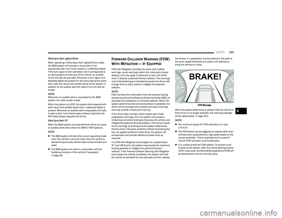
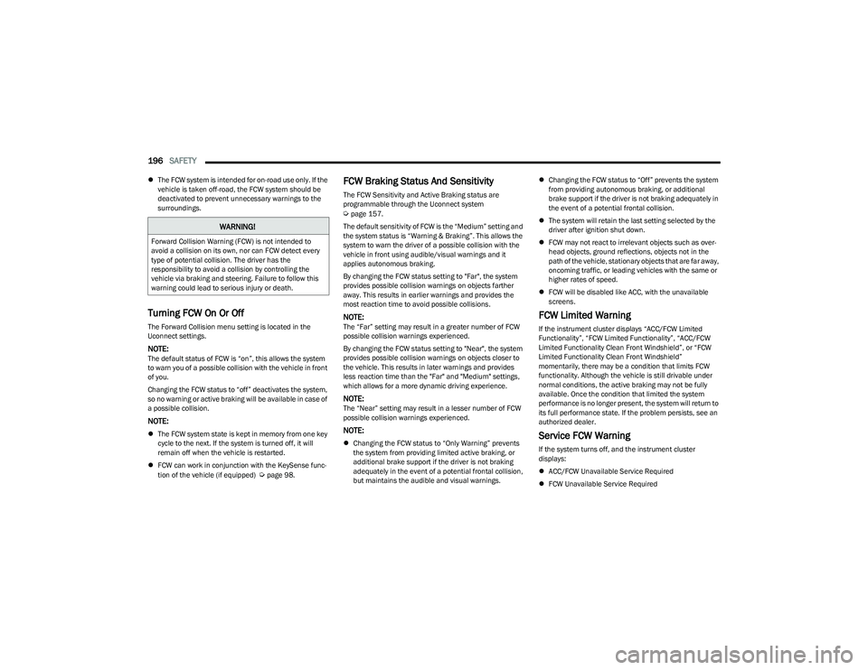
FCW Message
When the system determines a collision with the vehicle in
front of you is no longer probable, the warning message
will be deactivated
Úpage 312.
NOTE:
The minimum speed for FCW activation is 1 mph
(2 km/h).
The FCW alerts may be triggered on objects other than
vehicles such as guardrails or sign posts based on the
course prediction. This is expected and is a part of
normal FCW activation and functionality.
It is unsafe to test the FCW system. To prevent such
misuse of the system, after four Active Braking events
within a key cycle, the Active Braking portion of FCW will
be deactivated until the next key cycle.
6
23_RUP_OM_EN_USC_t.book Page 195
Page 198 of 328
196SAFETY
The FCW system is intended for on-road use only. If the
vehicle is taken off-road, the FCW system should be
deactivated to prevent unnecessary warnings to the
surroundings.
Turning FCW On Or Off
The Forward Collision menu setting is located in the
Uconnect settings.
NOTE:The default status of FCW is “on”, this allows the system
to warn you of a possible collision with the vehicle in front
of you.
Changing the FCW status to “off” deactivates the system,
so no warning or active braking will be available in case of
a possible collision.
NOTE:
The FCW system state is kept in memory from one key
cycle to the next. If the system is turned off, it will
remain off when the vehicle is restarted.
FCW can work in conjunction with the KeySense func -
tion of the vehicle (if equipped)
Úpage 98.
FCW Braking Status And Sensitivity
The FCW Sensitivity and Active Braking status are
programmable through the Uconnect system
Úpage 157.
The default sensitivity of FCW is the “Medium” setting and
the system status is “Warning & Braking”. This allows the
system to warn the driver of a possible collision with the
vehicle in front using audible/visual warnings and it
applies autonomous braking.
By changing the FCW status setting to "Far", the system
provides possible collision warnings on objects farther
away. This results in earlier warnings and provides the
most reaction time to avoid possible collisions.
NOTE:The “Far” setting may result in a greater number of FCW
possible collision warnings experienced.
By changing the FCW status setting to "Near", the system
provides possible collision warnings on objects closer to
the vehicle. This results in later warnings and provides
less reaction time than the "Far" and "Medium" settings,
which allows for a more dynamic driving experience.
NOTE:The “Near” setting may result in a lesser number of FCW
possible collision warnings experienced.
NOTE:
Changing the FCW status to “Only Warning” prevents
the system from providing limited active braking, or
additional brake support if the driver is not braking
adequately in the event of a potential frontal collision,
but maintains the audible and visual warnings.
Changing the FCW status to “Off” prevents the system
from providing autonomous braking, or additional
brake support if the driver is not braking adequately in
the event of a potential frontal collision.
The system will retain the last setting selected by the
driver after ignition shut down.
FCW may not react to irrelevant objects such as over -
head objects, ground reflections, objects not in the
path of the vehicle, stationary objects that are far away,
oncoming traffic, or leading vehicles with the same or
higher rates of speed.
FCW will be disabled like ACC, with the unavailable
screens.
FCW Limited Warning
If the instrument cluster displays “ACC/FCW Limited
Functionality”, “FCW Limited Functionality”, “ACC/FCW
Limited Functionality Clean Front Windshield”, or “FCW
Limited Functionality Clean Front Windshield”
momentarily, there may be a condition that limits FCW
functionality. Although the vehicle is still drivable under
normal conditions, the active braking may not be fully
available. Once the condition that limited the system
performance is no longer present, the system will return to
its full performance state. If the problem persists, see an
authorized dealer.
Service FCW Warning
If the system turns off, and the instrument cluster
displays:
ACC/FCW Unavailable Service Required
FCW Unavailable Service Required
WARNING!
Forward Collision Warning (FCW) is not intended to
avoid a collision on its own, nor can FCW detect every
type of potential collision. The driver has the
responsibility to avoid a collision by controlling the
vehicle via braking and steering. Failure to follow this
warning could lead to serious injury or death.
23_RUP_OM_EN_USC_t.book Page 196
Page 199 of 328
SAFETY197
This indicates there is an internal system fault. Although
the vehicle is still drivable under normal conditions, have
the system checked by an authorized dealer.
Pedestrian Emergency Braking (PEB) —
If Equipped
PEB is a subsystem of the FCW system which provides the
driver with audible and visual warnings in the instrument
cluster display, and may apply automatic braking when it
detects a potential frontal collision with a pedestrian.
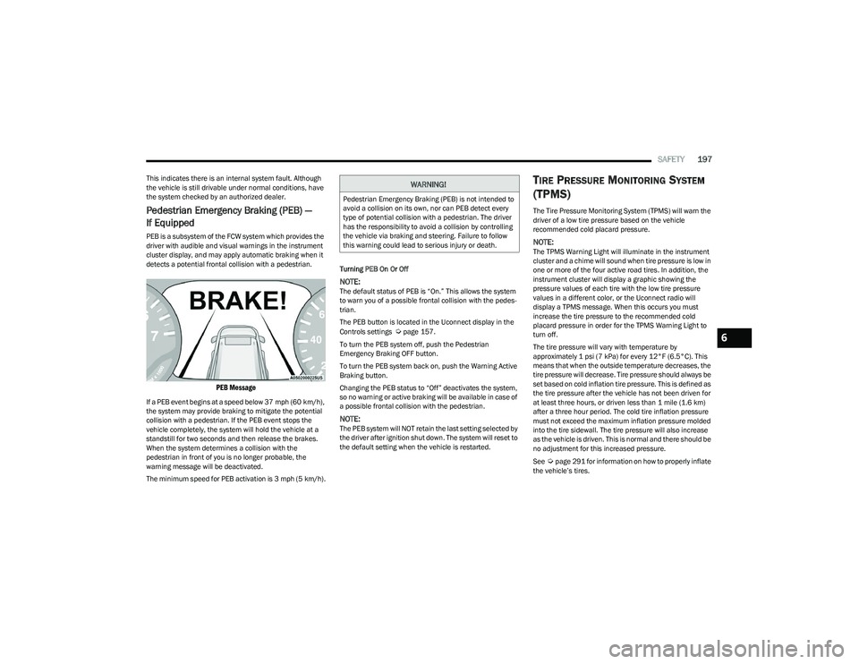
PEB Message
If a PEB event begins at a speed below 37 mph (60 km/h),
the system may provide braking to mitigate the potential
collision with a pedestrian. If the PEB event stops the
vehicle completely, the system will hold the vehicle at a
standstill for two seconds and then release the brakes.
When the system determines a collision with the
pedestrian in front of you is no longer probable, the
warning message will be deactivated.
The minimum speed for PEB activation is 3 mph (5 km/h). Turning PEB On Or Off
NOTE:The default status of PEB is “On.” This allows the system
to warn you of a possible frontal collision with the pedes
-
trian.
The PEB button is located in the Uconnect display in the
Controls settings
Úpage 157.
To turn the PEB system off, push the Pedestrian
Emergency Braking OFF button.
To turn the PEB system back on, push the Warning Active
Braking button.
Changing the PEB status to “Off” deactivates the system,
so no warning or active braking will be available in case of
a possible frontal collision with the pedestrian.
NOTE:The PEB system will NOT retain the last setting selected by
the driver after ignition shut down. The system will reset to
the default setting when the vehicle is restarted.
TIRE PRESSURE MONITORING SYSTEM
(TPMS)
The Tire Pressure Monitoring System (TPMS) will warn the
driver of a low tire pressure based on the vehicle
recommended cold placard pressure.
NOTE:The TPMS Warning Light will illuminate in the instrument
cluster and a chime will sound when tire pressure is low in
one or more of the four active road tires. In addition, the
instrument cluster will display a graphic showing the
pressure values of each tire with the low tire pressure
values in a different color, or the Uconnect radio will
display a TPMS message. When this occurs you must
increase the tire pressure to the recommended cold
placard pressure in order for the TPMS Warning Light to
turn off.
The tire pressure will vary with temperature by
approximately 1 psi (7 kPa) for every 12°F (6.5°C). This
means that when the outside temperature decreases, the
tire pressure will decrease. Tire pressure should always be
set based on cold inflation tire pressure. This is defined as
the tire pressure after the vehicle has not been driven for
at least three hours, or driven less than 1 mile (1.6 km)
after a three hour period. The cold tire inflation pressure
must not exceed the maximum inflation pressure molded
into the tire sidewall. The tire pressure will also increase
as the vehicle is driven. This is normal and there should be
no adjustment for this increased pressure.
See
Úpage 291 for information on how to properly inflate
the vehicle’s tires.
WARNING!
Pedestrian Emergency Braking (PEB) is not intended to
avoid a collision on its own, nor can PEB detect every
type of potential collision with a pedestrian. The driver
has the responsibility to avoid a collision by controlling
the vehicle via braking and steering. Failure to follow
this warning could lead to serious injury or death.
6
23_RUP_OM_EN_USC_t.book Page 197
Page 200 of 328
198SAFETY
The TPMS will warn the driver of a low tire pressure if the
tire pressure falls below the low-pressure warning limit for
any reason, including low temperature effects and natural
pressure loss through the tire.
The TPMS will continue to warn the driver of low tire
pressure as long as the condition exists, and will not turn
off until the tire pressure is at or above the recommended
cold placard pressure. Once the low tire pressure warning
(TPMS Warning Light) illuminates, you must increase the
tire pressure to the recommended cold placard pressure
in order for the TPMS Warning Light to turn off.
The system will automatically update and the TPMS
Warning Light will turn off once the system receives the
updated tire pressures. The vehicle may need to be driven
for up to 20 minutes above 15 mph (24 km/h) in order for
the TPMS to receive this information.
For example, your vehicle may have a recommended cold
(parked for more than three hours) placard pressure of
33 psi (227 kPa). If the ambient temperature is 68°F
(20°C) and the measured tire pressure is 28 psi
(193 kPa), a temperature drop to 20°F (-7°C) will
decrease the tire pressure to approximately 24 psi
(165 kPa). This tire pressure is low enough to turn on the
TPMS Warning Light. Driving the vehicle may cause the tire
pressure to rise to approximately 28 psi (193 kPa), but the
TPMS Warning Light will still be on. In this situation, the
TPMS Warning Light will turn off only after the tires are
inflated to the vehicle’s recommended cold placard
pressure value
Úpage 312.
NOTE:When filling warm tires, the tire pressure may need to be
increased up to an additional 4 psi (28 kPa) above the
recommended cold placard pressure in order to turn the
TPMS Warning Light off.NOTE:
The TPMS is not intended to replace normal tire care
and maintenance, or to provide warning of a tire failure
or condition.
The TPMS should not be used as a tire pressure gauge
while adjusting your tire pressure.
Driving on a significantly underinflated tire causes the
tire to overheat and can lead to tire failure. Underinfla -
tion also reduces fuel efficiency and tire tread life, and
may affect the vehicle’s handling and stopping ability.
The TPMS is not a substitute for proper tire mainte -
nance, and it is the driver’s responsibility to maintain
correct tire pressure using an accurate tire pressure
gauge, even if underinflation has not reached the level
to trigger illumination of the TPMS Warning Light.
Seasonal temperature changes will affect tire pres -
sure, and the TPMS will monitor the actual tire pres -
sure in the tire.
Premium System
The Tire Pressure Monitoring System (TPMS) uses wireless
technology with wheel rim mounted electronic sensors to
monitor tire pressure levels. Sensors, mounted to each
wheel as part of the valve stem, transmit tire pressure
readings to the receiver module.
NOTE:It is particularly important for you to check the tire
pressure in all of the tires on your vehicle monthly and to
maintain the proper pressure.
CAUTION!
The TPMS has been optimized for the original equip -
ment tires and wheels. TPMS pressures and warning
have been established for the tire size equipped on
your vehicle. Undesirable system operation or sensor
damage may result when using replacement equip -
ment that is not of the same size, type, and/or style.
The TPMS sensor is not designed for use on after -
market wheels and may contribute to a poor overall
system performance or sensor damage. Customers
are encouraged to use Original Equipment Manufac -
turer (OEM) wheels to ensure proper TPMS feature
operation.
Using aftermarket tire sealants may cause the Tire
Pressure Monitoring System (TPMS) sensor to
become inoperable. After using an aftermarket tire
sealant it is recommended that you take your vehicle
to an authorized dealer to have your sensor function
checked.
After inspecting or adjusting the tire pressure always
reinstall the valve stem cap. This will prevent mois -
ture and dirt from entering the valve stem, which
could damage the TPMS sensor.
23_RUP_OM_EN_USC_t.book Page 198
Page 218 of 328
216SAFETY
(Continued)
The SABIC deploys downward, covering the side windows.
An inflating SABIC pushes the outside edge of the
headliner out of the way and covers the window. The
SABICs inflate with enough force to injure occupants if
they are not belted and seated properly, or if items are
positioned in the area where the SABICs inflate. Children
are at an even greater risk of injury from a deploying air
bag.
The SABICs may help reduce the risk of partial or complete
ejection of vehicle occupants through side windows in
certain side impact events.
Side Impacts
The Side Air Bags are designed to activate in certain side
impacts. The Occupant Restraint Controller (ORC)
determines whether the deployment of the Side Air Bags
in a particular impact event is appropriate, based on the
severity and type of collision. The side impact sensors aid
the ORC in determining the appropriate response to
impact events. The system is calibrated to deploy the Side
Air Bags on the impact side of the vehicle during impacts
that require Side Air Bag occupant protection. In side
impacts, the Side Air Bags deploy independently; a left
side impact deploys the left Side Air Bags only and a
right-side impact deploys the right Side Air Bags only.
Vehicle damage by itself is not a good indicator of whether
or not Side Air Bags should have deployed.
The Side Air Bags will not deploy in all side collisions,
including some collisions at certain angles, or some side
collisions that do not impact the area of the passenger
compartment. The Side Air Bags may deploy during angled
or offset frontal collisions where the front air bags deploy.
Side Air Bags are a supplement to the seat belt restraint
system. Side Air Bags deploy in less time than it takes to
blink your eyes.
NOTE:Air bag covers may not be obvious in the interior trim, but
they will open during air bag deployment.
WARNING!
Do not mount equipment, or stack luggage or other
cargo up high enough to block the deployment of the
SABICs. The trim covering above the side windows
where the SABIC and its deployment path are located
should remain free from any obstructions.
In order for the SABICs to work as intended, do not
install any accessory items in your vehicle which
could alter the roof. Do not add an aftermarket
sunroof to your vehicle. Do not add roof racks that
require permanent attachments (bolts or screws) for
installation on the vehicle roof. Do not drill into the
roof of the vehicle for any reason.
WARNING!
Occupants, including children, who are up against or
very close to Side Air Bags can be seriously injured or
killed. Occupants, including children, should never
lean on or sleep against the door, side windows, or
area where the side air bags inflate, even if they are
in an infant or child restraint.
Seat belts (and child restraints where appropriate)
are necessary for your protection in all collisions.
They also help keep you in position, away from an
inflating Side Air Bag. To get the best protection from
the Side Air Bags, occupants must wear their seat
belts properly and sit upright with their backs against
the seats. Children must be properly restrained in a
child restraint or booster seat that is appropriate for
the size of the child.
WARNING!
Side Air Bags need room to inflate. Do not lean
against the door or window. Sit upright in the center
of the seat.
Being too close to the Side Air Bags during deploy -
ment could cause you to be severely injured or killed.
Relying on the Side Air Bags alone could lead to more
severe injuries in a collision. The Side Air Bags work
with your seat belt to restrain you properly. In some
collisions, Side Air Bags won’t deploy at all. Always
wear your seat belt even though you have Side Air
Bags.
WARNING!
23_RUP_OM_EN_USC_t.book Page 216