remove seats CHRYSLER PACIFICA HYBRID 2019 Owners Manual
[x] Cancel search | Manufacturer: CHRYSLER, Model Year: 2019, Model line: PACIFICA HYBRID, Model: CHRYSLER PACIFICA HYBRID 2019Pages: 620, PDF Size: 4.92 MB
Page 66 of 620
Push the button on the key fob twice within five
seconds to open, close, or reverse a power sliding
door.
The key fob and the overhead console button will operate
the door when the door is locked. All other ways require
the sliding door to be unlocked. If the vehicle is equipped
with Passive Entry, pressing the button on the outside
handle or Hands-Free feature (if equipped) will unlock and
open the sliding door, with a valid Passive Entry key fob
within 5 ft (1.5 m) of the door handle.
There are power sliding side door switches located on the
B-Pillar trim panel, just in front of the power sliding door
for the rear seat passengers.
To operate the sliding door manually with the handles or to
avoid unintentional operation of the power sliding doors
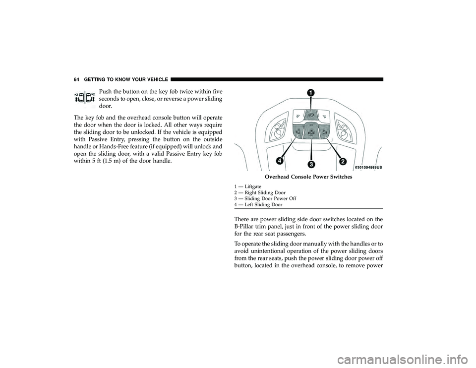
from the rear seats, push the power sliding door power off
button, located in the overhead console, to remove power
Overhead Console Power Switches
1 — Liftgate
2 — Right Sliding Door
3 — Sliding Door Power Off
4 — Left Sliding Door
64 GETTING TO KNOW YOUR VEHICLE
Page 90 of 620
HEAD RESTRAINTS
Head restraints are designed to reduce the risk of injury by
restricting head movement in the event of a rear impact.
Head restraints should be adjusted so that the top of the
head restraint is located above the top of your ear.
WARNING!
•All occupants, including the driver, should not oper-
ate a vehicle or sit in a vehicle’s seat until the head
restraints are placed in their proper positions in
order to minimize the risk of neck injury in the event
of a crash.
• Head restraints should never be adjusted while the
vehicle is in motion. Driving a vehicle with the head
restraints improperly adjusted or removed could
cause serious injury or death in the event of a
collision.
Head Restraints — Front Seats
The front driver and passenger seats are equipped with
four-way head restraints.
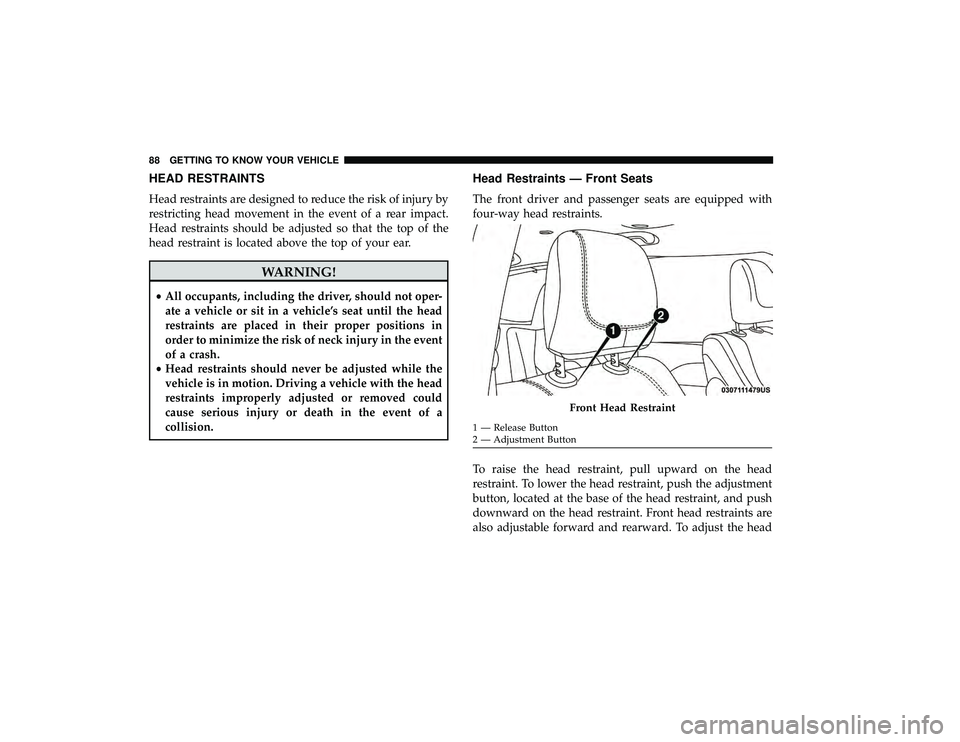
To raise the head restraint, pull upward on the head
restraint. To lower the head restraint, push the adjustment
button, located at the base of the head restraint, and push
downward on the head restraint. Front head restraints are
also adjustable forward and rearward. To adjust the head
Front Head Restraint
1 — Release Button
2 — Adjustment Button
88 GETTING TO KNOW YOUR VEHICLE
Page 94 of 620
Head Restraints — Third Row
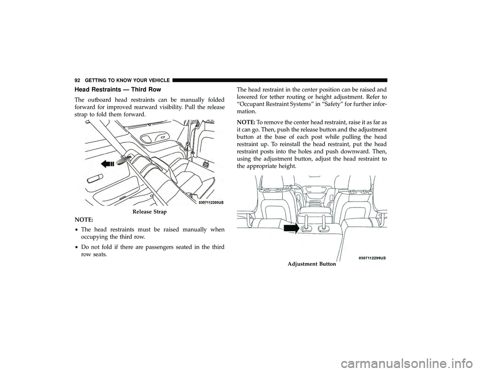
The outboard head restraints can be manually folded
forward for improved rearward visibility. Pull the release
strap to fold them forward.
NOTE:
•The head restraints must be raised manually when
occupying the third row.
• Do not fold if there are passengers seated in the third
row seats. The head restraint in the center position can be raised and
lowered for tether routing or height adjustment. Refer to
“Occupant Restraint Systems” in “Safety” for further infor-
mation.
NOTE:
To remove the center head restraint, raise it as far as
it can go. Then, push the release button and the adjustment
button at the base of each post while pulling the head
restraint up. To reinstall the head restraint, put the head
restraint posts into the holes and push downward. Then,
using the adjustment button, adjust the head restraint to
the appropriate height.
Release Strap
Adjustment Button
92 GETTING TO KNOW YOUR VEHICLE
Page 140 of 620
•If the power liftgate encounters multiple obstructions
within the same cycle, the system will automatically
stop. If this occurs, the liftgate must be operated manu-
ally.
• The power liftgate will release, but not power open, in
temperatures below �12° F (�24° C). Be sure to remove
any buildup of snow or ice from the liftgate before
opening the liftgate.
• If the liftgate is left open for an extended period of time,
the liftgate may need to be closed manually to reset
power liftgate functionality.
WARNING!
• Driving with the liftgate open can allow poisonous
exhaust gases into your vehicle. You and your pas-
sengers could be injured by these fumes. Keep the
liftgate closed when you are operating the vehicle.
• If you are required to drive with the liftgate open,
make sure that all windows are closed, and the
climate control blower switch is set at high speed. Do
not use the recirculation mode. Gas props support the liftgate in the open position. How-
ever, because the gas pressure drops with temperature, it
may be necessary to assist the props when opening the
liftgate in cold weather.
NOTE:
Allow the power system to open the liftgate.
Manually pushing or pulling the liftgate may activate the
liftgate obstacle detection feature and stop the power
operation or reverse its direction.
WARNING!
During power operation, personal injury or cargo
damage may occur. Ensure the liftgate travel path is
clear. Make sure the liftgate is closed and latched
before driving away.
Cargo Area Features
Cargo Area Storage
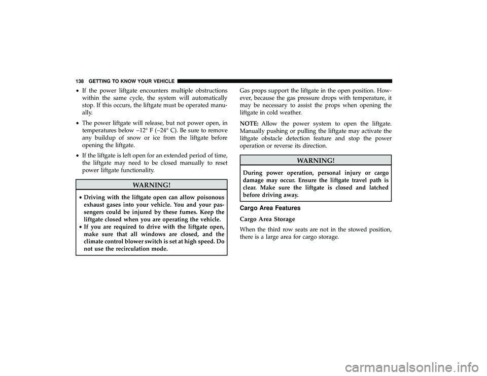
When the third row seats are not in the stowed position,
there is a large area for cargo storage.
138 GETTING TO KNOW YOUR VEHICLE
Page 141 of 620
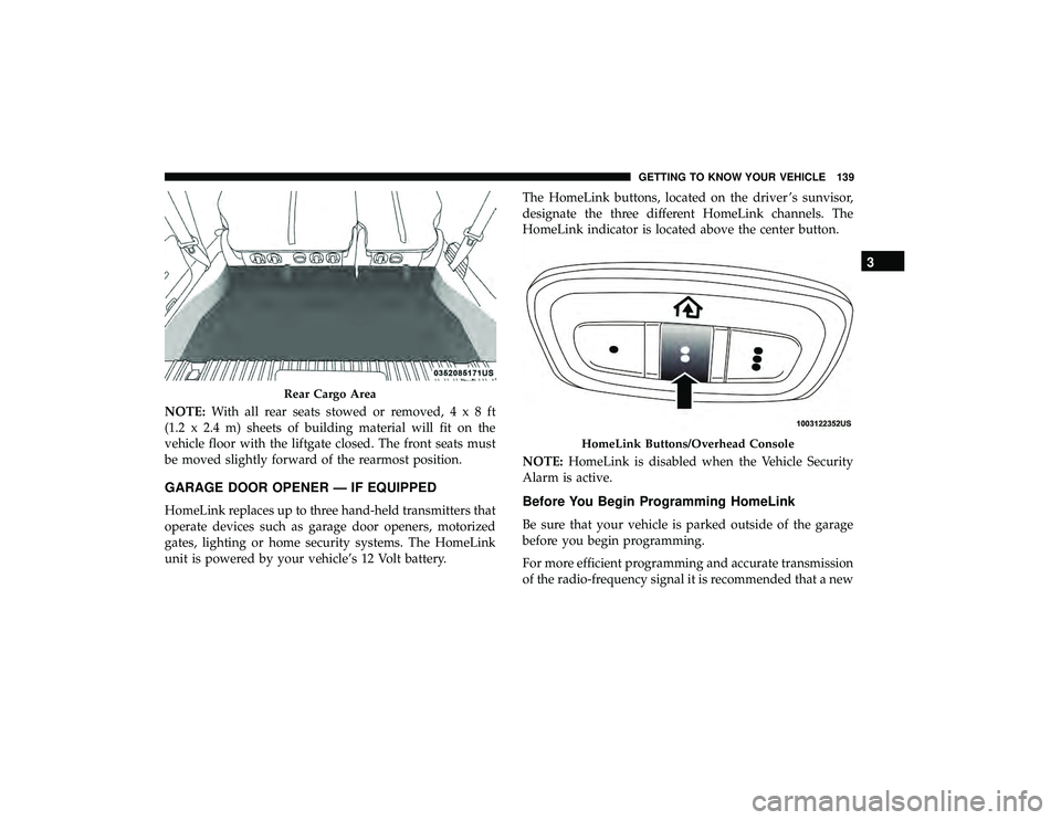
NOTE:With all rear seats stowed or removed,4x8ft
(1.2 x 2.4 m) sheets of building material will fit on the
vehicle floor with the liftgate closed. The front seats must
be moved slightly forward of the rearmost position.
GARAGE DOOR OPENER — IF EQUIPPED
HomeLink replaces up to three hand-held transmitters that
operate devices such as garage door openers, motorized
gates, lighting or home security systems. The HomeLink
unit is powered by your vehicle’s 12 Volt battery. The HomeLink buttons, located on the driver ’s sunvisor,
designate the three different HomeLink channels. The
HomeLink indicator is located above the center button.
NOTE:
HomeLink is disabled when the Vehicle Security
Alarm is active.Before You Begin Programming HomeLink
Be sure that your vehicle is parked outside of the garage
before you begin programming.
For more efficient programming and accurate transmission
of the radio-frequency signal it is recommended that a new
Rear Cargo Area
HomeLink Buttons/Overhead Console
3
GETTING TO KNOW YOUR VEHICLE 139
Page 154 of 620
CAUTION!(Continued)
recharge the vehicle’s battery or plug the vehicle in
with EVSE charger.
• The vehicle uses a power inverter connected to the
HV battery to charge the 12V battery as well as
supports the 12V electrical loads, when the vehicle is
not ON.
Power Inverter — If Equipped
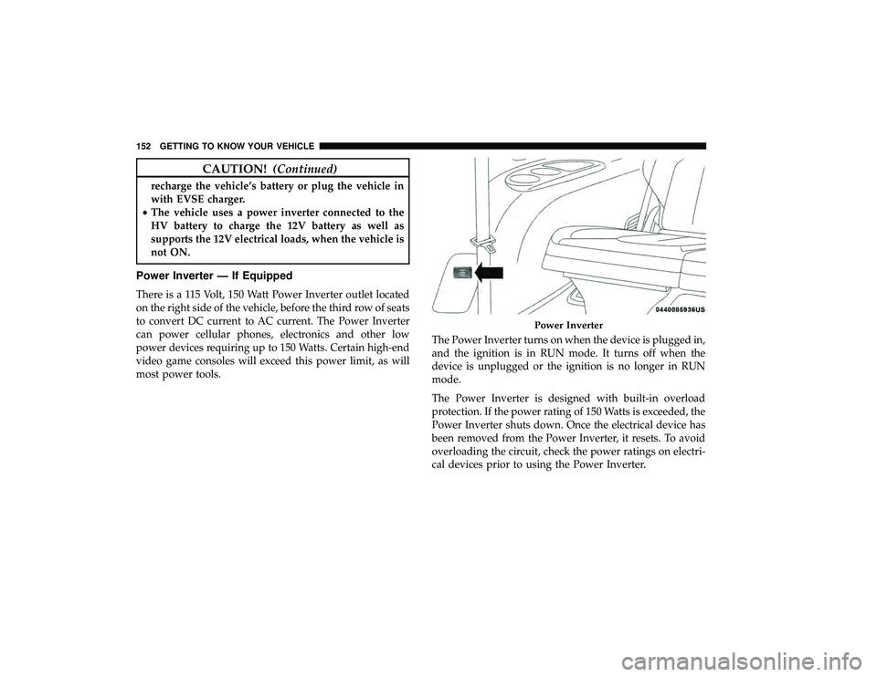
There is a 115 Volt, 150 Watt Power Inverter outlet located
on the right side of the vehicle, before the third row of seats
to convert DC current to AC current. The Power Inverter
can power cellular phones, electronics and other low
power devices requiring up to 150 Watts. Certain high-end
video game consoles will exceed this power limit, as will
most power tools. The Power Inverter turns on when the device is plugged in,
and the ignition is in RUN mode. It turns off when the
device is unplugged or the ignition is no longer in RUN
mode.
The Power Inverter is designed with built-in overload
protection. If the power rating of 150 Watts is exceeded, the
Power Inverter shuts down. Once the electrical device has
been removed from the Power Inverter, it resets. To avoid
overloading the circuit, check the power ratings on electri-
cal devices prior to using the Power Inverter.
Power Inverter
152 GETTING TO KNOW YOUR VEHICLE
Page 229 of 620
Second Row Center (If Equipped) And Third Row
Center Seat Belt Operating Instructions
The second row center (if equipped) and third row center
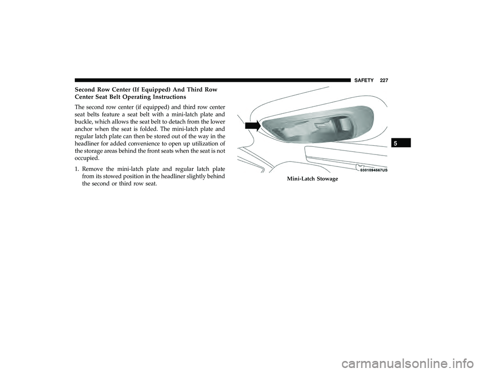
seat belts feature a seat belt with a mini-latch plate and
buckle, which allows the seat belt to detach from the lower
anchor when the seat is folded. The mini-latch plate and
regular latch plate can then be stored out of the way in the
headliner for added convenience to open up utilization of
the storage areas behind the front seats when the seat is not
occupied.
1. Remove the mini-latch plate and regular latch platefrom its stowed position in the headliner slightly behind
the second or third row seat.
Mini-Latch Stowage
5
SAFETY 227
Page 236 of 620
How To Disengage The Automatic Locking Mode
Unbuckle the combination lap/shoulder belt and allow it
to retract completely to disengage the Automatic Locking
Mode and activate the vehicle sensitive (emergency) lock-
ing mode.
WARNING!
•The seat belt assembly must be replaced if the
switchable Automatic Locking Retractor (ALR) fea-
ture or any other seat belt function is not working
properly when checked according to the procedures
in the Service Manual.
• Failure to replace the seat belt assembly could in-
crease the risk of injury in collisions.
• Do not use the Automatic Locking Mode to restrain
occupants who are wearing the seat belt or children
who are using booster seats. The locked mode is only
used to install rear-facing or forward-facing child
restraints that have a harness for restraining the
child.
Seat Belt Park Stitch — If Equipped
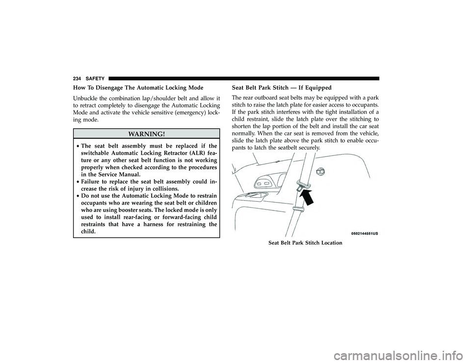
The rear outboard seat belts may be equipped with a park
stitch to raise the latch plate for easier access to occupants.
If the park stitch interferes with the tight installation of a
child restraint, slide the latch plate over the stitching to
shorten the lap portion of the belt and install the car seat
normally. When the car seat is removed from the vehicle,
slide the latch plate above the park stitch to enable occu-
pants to latch the seatbelt securely.
Seat Belt Park Stitch Location
234 SAFETY
Page 262 of 620
WARNING!
•Improper installation can lead to failure of an infant
or child restraint. It could come loose in a collision.
The child could be badly injured or killed. Follow
the child restraint manufacturer ’s directions exactly
when installing an infant or child restraint.
• After a child restraint is installed in the vehicle, do
not move the vehicle seat forward or rearward be-
cause it can loosen the child restraint attachments.
Remove the child restraint before adjusting the ve-
hicle seat position. When the vehicle seat has been
adjusted, reinstall the child restraint.
• When your child restraint is not in use, secure it in
the vehicle with the seat belt or LATCH anchorages,
or remove it from the vehicle. Do not leave it loose in
the vehicle. In a sudden stop or accident, it could
strike the occupants or seatbacks and cause serious
personal injury.
Children Too Large For Booster Seats
Children who are large enough to wear the shoulder belt
comfortably, and whose legs are long enough to bend over
the front of the seat when their back is against the seatback, should use the seat belt in a rear seat. Use this simple 5-step
test to decide whether the child can use the vehicle’s seat
belt alone:
1. Can the child sit all the way back against the back of the
vehicle seat?
2. Do the child’s knees bend comfortably over the front of the vehicle seat – while the child is still sitting all the
way back?
3. Does the shoulder belt cross the child’s shoulder be- tween the neck and arm?
4. Is the lap part of the belt as low as possible, touching the child’s thighs and not the stomach?
5. Can the child stay seated like this for the whole trip?
If the answer to any of these questions was “no,” then the
child still needs to use a booster seat in this vehicle. If the
child is using the lap/shoulder belt, check seat belt fit
periodically and make sure the seat belt buckle is latched.
A child’s squirming or slouching can move the belt out of
position. If the shoulder belt contacts the face or neck,
move the child closer to the center of the vehicle, or use a
booster seat to position the seat belt on the child correctly.
260 SAFETY
Page 271 of 620
5. Tighten all of the straps as you push the child restraintrearward and downward into the seat. Remove slack in
the straps according to the child restraint manufactur-
er ’s instructions.
6. Test that the child restraint is installed tightly by pulling back and forth on the child seat at the belt path. It
should not move more than 1 inch (25.4 mm) in any
direction.
How To Stow An Unused Switchable-ALR (ALR)
Seat Belt:
When using the LATCH attaching system to install a child
restraint, stow all ALR seat belts that are not being used by
other occupants or being used to secure child restraints. An
unused belt could injure a child if they play with it and
accidentally lock the seat belt retractor. Before installing a
child restraint using the LATCH system, buckle the seat
belt behind the child restraint and out of the child’s reach.
If the buckled seat belt interferes with the child restraint
installation, instead of buckling it behind the child re-
straint, route the seat belt through the child restraint belt
path and then buckle it. Do not lock the seat belt. Remind
all children in the vehicle that the seat belts are not toys and
that they should not play with them.
WARNING!
•Improper installation of a child restraint to the
LATCH anchorages can lead to failure of the re-
straint. The child could be badly injured or killed.
Follow the child restraint manufacturer ’s directions
exactly when installing an infant or child restraint.
• Child restraint anchorages are designed to withstand
only those loads imposed by correctly-fitted child
restraints. Under no circumstances are they to be
used for adult seat belts, harnesses, or for attaching
other items or equipment to the vehicle.
Installing Child Restraints Using The Vehicle Seat
Belt
Child restraint systems are designed to be secured in
vehicle seats by lap belts or the lap belt portion of a
lap/shoulder belt.
WARNING!
• Improper installation or failure to properly secure a
child restraint can lead to failure of the restraint. The
child could be badly injured or killed.
(Continued)
5
SAFETY 269