clock CHRYSLER PACIFICA HYBRID 2021 Owners Manual
[x] Cancel search | Manufacturer: CHRYSLER, Model Year: 2021, Model line: PACIFICA HYBRID, Model: CHRYSLER PACIFICA HYBRID 2021Pages: 401, PDF Size: 26.88 MB
Page 66 of 401
64GETTING TO KNOW YOUR VEHICLE
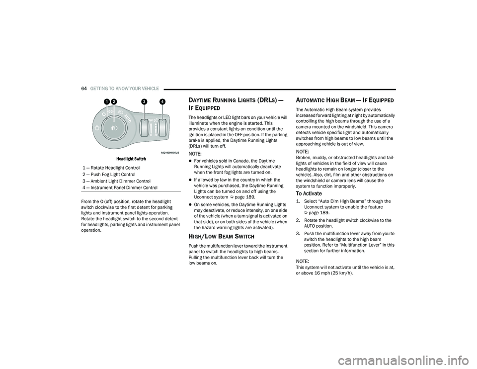
Headlight Switch
From the O (off) position, rotate the headlight
switch clockwise to the first detent for parking
lights and instrument panel lights operation.
Rotate the headlight switch to the second detent
for headlights, parking lights and instrument panel
operation.
DAYTIME RUNNING LIGHTS (DRLS) —
I
F EQUIPPED
The headlights or LED light bars on your vehicle will
illuminate when the engine is started. This
provides a constant lights on condition until the
ignition is placed in the OFF position. If the parking
brake is applied, the Daytime Running Lights
(DRLs) will turn off.
NOTE:
For vehicles sold in Canada, the Daytime
Running Lights will automatically deactivate
when the front fog lights are turned on.
If allowed by law in the country in which the
vehicle was purchased, the Daytime Running
Lights can be turned on and off using the
Uconnect system Ú page 189.
On some vehicles, the Daytime Running Lights
may deactivate, or reduce intensity, on one side
of the vehicle (when a turn signal is activated on
that side), or on both sides of the vehicle (when
the hazard warning lights are activated).
HIGH/LOW BEAM SWITCH
Push the multifunction lever toward the instrument
panel to switch the headlights to high beams.
Pulling the multifunction lever back will turn the
low beams on.
AUTOMATIC HIGH BEAM — IF EQUIPPED
The Automatic High Beam system provides
increased forward lighting at night by automatically
controlling the high beams through the use of a
camera mounted on the windshield. This camera
detects vehicle specific light and automatically
switches from high beams to low beams until the
approaching vehicle is out of view.
NOTE:Broken, muddy, or obstructed headlights and tail -
lights of vehicles in the field of view will cause
headlights to remain on longer (closer to the
vehicle). Also, dirt, film and other obstructions on
the windshield or camera lens will cause the
system to function improperly.
To Activate
1. Select “Auto Dim High Beams” through the Uconnect system to enable the feature
Ú
page 189.
2. Rotate the headlight switch clockwise to the AUTO position.
3. Push the multifunction lever away from you to switch the headlights to the high beam
position. Refer to “Multifunction Lever” in this
section for further information.
NOTE:This system will not activate until the vehicle is at,
or above 16 mph (25 km/h).
1 — Rotate Headlight Control
2 — Push Fog Light Control
3 — Ambient Light Dimmer Control
4 — Instrument Panel Dimmer Control
21_RUP_OM_EN_USC_t.book Page 64
Page 67 of 401
GETTING TO KNOW YOUR VEHICLE65
To Deactivate
Perform either of the following steps to deactivate
the Automatic High Beam system.
1. Deselect “Auto Dim High Beams” through the
Uconnect system
Ú
page 189.
2. Pull the multifunction lever toward you to switch the headlights from the high beam to
the low beam position.
3. Rotate the headlight switch counterclockwise from the AUTO to the on position.
NOTE:Once active, the Automatic High Beam system will
stop functioning below 12 mph (20 km/h).
FLASH-TO-PASS
You can signal another vehicle with your headlights
by lightly pulling the multifunction lever toward you.
This will cause the high beam headlights to turn on,
and remain on, until the lever is released.
AUTOMATIC HEADLIGHTS — IF EQUIPPED
This system automatically turns your headlights on
or off based on ambient light levels. To turn the
system on, turn the headlight switch to the extreme
clockwise position aligning the indicator with the
AUTO on the headlight switch. When the system is
on, the Headlight Time Delay feature is also on. This means your headlights will stay on for up to
90 seconds after the ignition is placed in the OFF
position. To turn the automatic system off, turn the
headlight switch counterclockwise to the O (off)
position.
NOTE:The engine must be running before the headlights
will come on in the Automatic mode.
HEADLIGHTS ON WITH WIPERS —
I
F EQUIPPED
When your headlights are in the AUTO mode and
the engine is running, the headlights will
automatically turn on when the wiper system is
also turned on. Headlights on when windshield
wipers are on may be found on vehicles equipped
with an automatic headlight system.
NOTE:The Headlights with Wipers feature can be turned
on or off through the Uconnect system
Ú page 189.
HEADLIGHT TIME DELAY — IF EQUIPPED
This feature provides the safety of headlight
illumination for up to 90 seconds after exiting your
vehicle. To activate the delay feature, place the ignition in
the OFF position while the headlights are still on.
The 90 second delay interval begins when
headlight switch is turned off. If the headlights or
parking lights are turned back on or the ignition is
placed in the ON position, the delay will be
cancelled.
When exiting the vehicle the driver can choose to
have the headlights remain on for 30, 60, or 90
seconds or not remain on. You can change the
timer setting through the Uconnect system
Ú
page 189.
If the headlights are turned off before the ignition,
they will turn off in the normal manner.
NOTE:The headlights must be turned off within 45
seconds of placing the ignition in the OFF position
to activate this feature.
LIGHTS-ON REMINDER
If the headlights or the parking lights are left on
after the ignition is placed in the OFF position, the
vehicle will chime when the driver's door is opened.
2
21_RUP_OM_EN_USC_t.book Page 65
Page 74 of 401
72GETTING TO KNOW YOUR VEHICLE
NOTE:The SYNC setting is only available on the touch -
screen.
Blower Control
Blower Control regulates the amount of
air forced through the climate control
system. There are seven blower speeds
available. Adjusting the blower will cause
automatic mode to switch to manual operation.
The speeds can be selected using either the
blower control knob on the faceplate or the
buttons on the touchscreen.
Faceplate: The blower speed increases as you
turn the blower control knob clockwise from the
lowest blower setting. The blower speed
decreases as you turn the blower control knob
counterclockwise.
Touchscreen: Use the small blower icon to
reduce the blower setting and the large blower
icon to increase the blower setting. Blower
speed can also be selected by pressing the
blower bar area between the icons.
Mode Control
The airflow distribution mode can be
adjusted so air comes from the
instrument panel outlets, floor outlets,
defrost outlets and demist outlets.
Faceplate: Push the button in the center of the
knob to change the airflow distribution mode.
Touchscreen: Select Mode by pressing one of the
Mode Buttons on the touchscreen.
Panel Mode
Air comes from the outlets in the
instrument panel. Each of these outlets
can be individually adjusted to direct the
flow of air. The air vanes of the center
outlets and outboard outlets can be moved up and
down or side to side to regulate airflow direction.
There is a shut-off wheel located below the air
vanes to shut off or adjust the amount of airflow
from these outlets.
Bi-Level Mode
Air comes from the instrument panel
outlets and floor outlets. A slight amount
of air is directed through the defrost and
side window demister outlets.
NOTE:Bi-Level mode is designed under comfort condi -
tions to provide cooler air out of the panel outlets
and warmer air from the floor outlets.
Floor Mode
Air comes from the floor outlets. A slight
amount of air is directed through the
defrost and side window demister
outlets.
Mix Mode
Air is directed through the floor, defrost,
and side window demister outlets. This
setting works best in cold or snowy
conditions that require extra heat to the
windshield. This setting is good for maintaining
comfort while reducing moisture on the
windshield.
Climate Control OFF Button
Press and release this button to turn the
Climate Control ON/OFF.
21_RUP_OM_EN_USC_t.book Page 72
Page 80 of 401
78GETTING TO KNOW YOUR VEHICLE
NOTE:The SYNC setting is only available on the touch -
screen.
Blower Control
Blower Control is used to regulate the
amount of air forced through the Climate
Control system. There are seven blower
speeds available. The speeds can be
selected using either the blower control knob on
the faceplate or the buttons on the touchscreen.
Faceplate: The blower speed increases as you
turn the blower control knob clockwise from the
lowest blower setting. The blower speed
decreases as you turn the blower control knob
counterclockwise.
Touchscreen: Use the small blower icon to
reduce the blower setting and the large blower
icon to increase the blower setting. Blower
speed can also be selected by pressing the
blower bar area between the icons.
Mode Control
The airflow distribution mode can be
adjusted so air comes from the
instrument panel outlets, floor outlets,
defrost outlets and demist outlets.
Faceplate: Push the button in the center of the
knob to change the airflow distribution mode.
Touchscreen: Select Mode by pressing one of the
Mode Buttons on the touchscreen.
Panel Mode
Air comes from the outlets in the
instrument panel. Each of these outlets
can be individually adjusted to direct the
flow of air. The air vanes of the center
outlets and outboard outlets can be moved up and
down or side to side to regulate airflow direction.
There is a shut-off wheel located below the air
vanes to shut off or adjust the amount of airflow
from these outlets.
Bi-Level Mode
Air comes from the instrument panel
outlets and floor outlets. A slight amount
of air is directed through the defrost and
side window demister outlets.
NOTE:Bi-Level mode is designed under comfort condi -
tions to provide cooler air out of the panel outlets
and warmer air from the floor outlets.
Floor Mode
Air comes from the floor outlets. A slight
amount of air is directed through the
defrost and side window demister
outlets.
Mix Mode
Air is directed through the floor, defrost,
and side window demister outlets. This
setting works best in cold or snowy
conditions that require extra heat to the
windshield. This setting is good for maintaining
comfort while reducing moisture on the
windshield.
Climate Control OFF Button
Press and release this button to turn the
Climate Control ON/OFF.
21_RUP_OM_EN_USC_t.book Page 78
Page 107 of 401
GETTING TO KNOW YOUR VEHICLE105
5. When finished, push power button to turn vacuum off and store vacuum hose and any
attachments.
6. Before exiting the vehicle:
If the ignition is in the ACC position, push
the START/STOP ignition button to place
ignition in the OFF position, remove key fob
from the vehicle, and lock the vehicle.
If the engine is running, raise all of the
windows, push the START/STOP ignition
button to place ignition in the OFF position,
remove key fob from the vehicle, close all of
the doors and the liftgate and lock the
vehicle. Vacuum Troubleshooting
DO NOT use with any opening blocked. If an
object becomes lodged in the hose, attempt to
fully extend the hose in a straight line while the
vacuum motor is running. If this does not
dislodge the object, turn the vacuum OFF and
remove the hose from the vehicle following the
removal instructions below. If the filter is
clogged, follow the emptying debris bin proce
-
dure and lightly tap the filter on the collection
bin to remove any collected debris from the
filter. Both the bin and the filter can be rinsed
with water if needed. To avoid mold and stale
odors, allow both to dry completely before rein -
stalling in your vehicle. If the filter has tears,
holes or other damage and needs to be
replaced, please contact an authorized dealer.
If there are any other issues with your vacuum,
contact an authorized dealer. Your vacuum has
no user serviceable parts.
Debris Bin
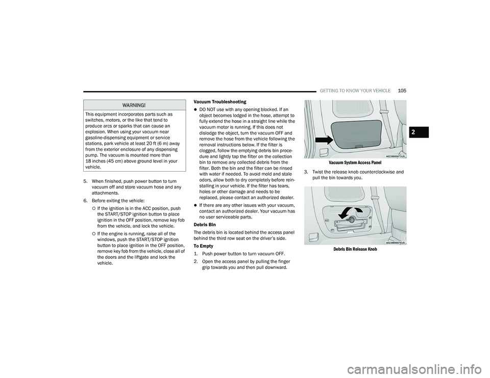
The debris bin is located behind the access panel
behind the third row seat on the driver’s side.
To Empty
1. Push power button to turn vacuum OFF.
2. Open the access panel by pulling the finger grip towards you and then pull downward.
Vacuum System Access Panel
3. Twist the release knob counterclockwise and pull the bin towards you.
Debris Bin Release Knob
WARNING!
This equipment incorporates parts such as
switches, motors, or the like that tend to
produce arcs or sparks that can cause an
explosion. When using your vacuum near
gasoline-dispensing equipment or service
stations, park vehicle at least 20 ft (6 m) away
from the exterior enclosure of any dispensing
pump. The vacuum is mounted more than
18 inches (45 cm) above ground level in your
vehicle.
2
21_RUP_OM_EN_USC_t.book Page 105
Page 145 of 401
STARTING AND OPERATING143
The following indicators should be used to ensure
that you have properly engaged the transmission
into the PARK position:
Look at the transmission gear position display
and verify that it indicates the PARK position (P),
and is not blinking.
With brake pedal released, verify that the gear
selector will not move out of PARK.
REVERSE (R)
This range is for moving the vehicle backward.
Shift into REVERSE only after the vehicle has come
to a complete stop.
NEUTRAL (N)
Use this range when the vehicle is standing for
prolonged periods with the engine running. The
engine may be started in this range. Apply the
parking brake and shift the transmission into PARK
if you must exit the vehicle.
DRIVE (D)
This range should be used for most city and
highway driving. It provides the smoothest upshifts
and downshifts, and the best fuel economy. The
transmission automatically upshifts through all
forward gears. The DRIVE position provides
optimum driving characteristics under all normal
operating conditions.
If the transmission temperature exceeds normal
operating limits, the transmission controller may
modify the transmission shift schedule, reduce
engine torque, and/or expand the range of torque
converter clutch engagement. This is done to
prevent transmission damage due to overheating.
If the transmission becomes extremely hot, the
“Transmission Temperature Warning Light” will
illuminate, a warning message will appear in the
instrument cluster, and the transmission may
operate differently until the transmission cools
down. During cold temperatures, transmission operation
may be modified depending on engine and
transmission temperature as well as vehicle
speed. This feature improves warm up time of the
engine and transmission to achieve maximum
efficiency. Engagement of the torque converter
clutch, and shifts into EIGHTH or NINTH gear, are
inhibited until the transmission fluid is warm
Ú
page 144. Normal operation will resume once
the transmission temperature has risen to a
suitable level.LOW (L)
Use this range for engine braking when
descending very steep grades. In this range, the
transmission will downshift for increased engine
braking. To access the LOW position, push down
on the gear selector and rotate it fully clockwise.
Transmission Limp Home Mode
Transmission function is monitored electronically
for abnormal conditions. If a condition is detected
that could result in transmission damage,
Transmission Limp Home Mode is activated. In this
mode, the transmission may operate only in a fixed
gear, or may remain in NEUTRAL. The Malfunction
Indicator Light (MIL) may be illuminated. Limp
Home Mode may allow the vehicle to be driven to
an authorized dealer for service without damaging
the transmission.
WARNING!
Do not coast in NEUTRAL and never turn off the
ignition to coast down a hill. These are unsafe
practices that limit your response to changing
traffic or road conditions. You might lose control
of the vehicle and have a collision.
CAUTION!
Towing the vehicle, coasting, or driving for any
other reason with the transmission in NEUTRAL
can cause severe transmission damage.
For Recreational Towing Ú page 185.
For Towing A Disabled Vehicle Ú page 324.
4
21_RUP_OM_EN_USC_t.book Page 143
Page 177 of 401
STARTING AND OPERATING175
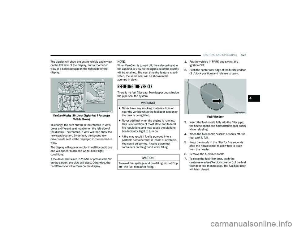
The display will show the entire vehicle cabin view
on the left side of the display, and a zoomed-in
view of a selected seat on the right side of the
display.
FamCam Display (10.1-inch Display And 7 Passenger Vehicle Shown)
To change the seat shown in the zoomed-in view,
press a different seat location on the left side of
the display. The zoomed-in view will then show the
new seat location. By default, the second row
driver’s side seat will be displayed in the zoomed-in
view.
The display will appear in color in well-lit conditions
and will appear black and white in low light
conditions.
If the driver shifts into REVERSE or presses the “X”
on the screen, the view will close. Otherwise, the
FamCam view will remain on the display.
NOTE:When FamCam is turned off, the selected seat in
the zoomed-in view on the right side of the display
will be retained. The next time the feature is acti -
vated, the same seat will be shown in the
zoomed-in view.
REFUELING THE VEHICLE
There is no fuel filler cap. Two flapper doors inside
the pipe seal the system.
1. Put the vehicle in PARK and switch the
ignition OFF.
2. Push the center-rear edge of the fuel filler door (3 o'clock position) and release to open.
Fuel Filler Door
3. Insert the fuel nozzle fully into the filler pipe; the nozzle opens and holds both flapper doors
while refueling.
4. When the fuel nozzle “clicks” or shuts off, the fuel tank is full.
5. Keep the nozzle in the filler for five seconds after the nozzle clicks to allow fuel to drain
from the nozzle.
6. Remove the fuel filler nozzle.
7. To close the fuel filler door, push the center-rear edge (3 o’clock position) of the fuel
filler door and then release. The fuel filler door
will latch closed.
WARNING!
Never have any smoking materials lit in or
near the vehicle when the fuel door is open or
the tank is being filled.
Never add fuel when the engine is running.
This is in violation of most state and federal
fire regulations and may cause the Malfunc -
tion Indicator Light to turn on.
A fire may result if fuel is pumped into a
portable container that is inside of a vehicle.
You could be burned. Always place fuel
containers on the ground while filling.
CAUTION!
To avoid fuel spillage and overfilling, do not “top
off” the fuel tank after filling.
4
21_RUP_OM_EN_USC_t.book Page 175
Page 200 of 401
198MULTIMEDIA
Clock & Date
After pressing the Clock & Date button on the touchscreen, the following settings will be available:
NOTE:Depending on the vehicle’s options, feature settings may vary.
Setting Name Description
Sync Time With GPS This setting will sync the time to the GPS receiver in the system. The system
will control the time via the GPS location.
Set Time This setting will allow you to manually set the time of your clock.
Time Format This setting will allow you to set the time format (AM/PM). Sync Time With GPS
must be off for this setting to be available. The “12 hrs” setting will set the
time to a 12-hour format. The “24 hrs” setting will set the time to a 24-hour
format.
Set Date This setting will allow you to set the date by day, month, and year
(DD/MM/YY).
Set Time Hour This setting will allow you to set the hours. Sync Time With GPS must be off for
this setting to be available. The “+” setting will increase the hours. The “-”
setting will decrease the hours.
Set Time Minutes This setting will allow you to set the minutes. Sync Time With GPS must be off
for this setting to be available. The “+” setting will increase the minutes. The
“-” setting will decrease the minutes.
Show Time in Status Bar This setting will place the time in the radio’s status bar.
21_RUP_OM_EN_USC_t.book Page 198
Page 221 of 401
MULTIMEDIA219
General Settings
To change source card order, select “Source Card
Reorder”, then press and hold source card on the
touchscreen, and drag and drop in desired order.
You can also adjust settings such as:
Brightness
Media port lighting on and off
Clock on and off
NOTE:System information can also be displayed under
General Settings.
Remote Settings
Under this setting, you can access the following:
Manage Remotes (this allows you to unpair
remotes)
Pair Remote
Remote sensitivity (this adjusts the speed and
sensitivity of cursor on screen when using
gesture pad) Ú page 387.
PLAY A DVD/BLU-RAY™ OR USB
M
EDIA FILE FROM UCONNECT SYSTEM
1. Insert a Blu-ray™ Disc or DVD disc into the
disc player with the label facing up, or insert a
USB drive into rear Video USB port.
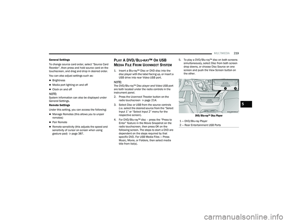
NOTE:The DVD/Blu-ray™ Disc player and Video USB port
are both located under the radio controls in the
instrument panel.
2. Press the Uconnect Theater button on the radio touchscreen Ú page 214.
3. Select Disc or USB from the source controls (i.e. select the desired source from the “Select
Input 1” or “Select Input 2” menu for the
respective screen).
4. For DVD/Blu-ray™ disc – press the “Press to Enter” feature in the Movie Snapshot on the
radio touchscreen, then press OK on the
following screen. The steps to start a DVD are
dependent on the steps required by that
specific DVD. For USB Media Files — Press
Music, Movie, or Folders, then select media
title from list(s). 5. To play a DVD/Blu-ray™ disc on both screens
simultaneously, select Disc from both screen
drop downs, or choose Disc Source on one
screen and push the View Screen button on
the other.
DVD/Blu-ray™ Disc Player
1 — DVD/Blu-ray Player
2 — Rear Entertainment USB Ports
5
21_RUP_OM_EN_USC_t.book Page 219
Page 302 of 401
300IN CASE OF EMERGENCY
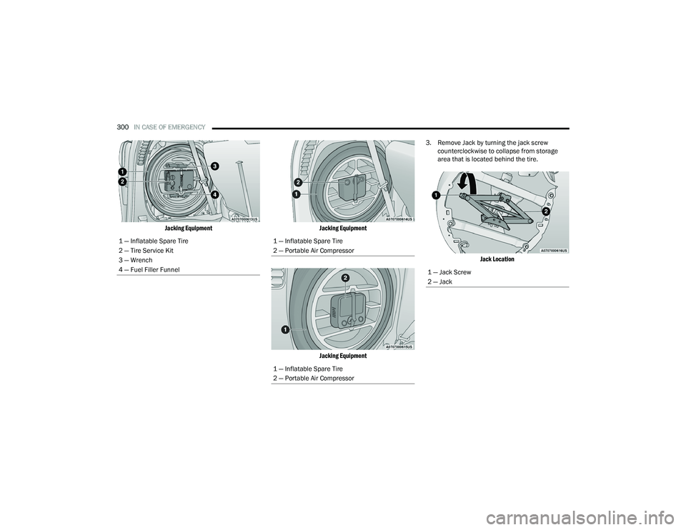
Jacking Equipment Jacking Equipment
Jacking Equipment
3. Remove Jack by turning the jack screw
counterclockwise to collapse from storage
area that is located behind the tire.
Jack Location
1 — Inflatable Spare Tire
2 — Tire Service Kit
3 — Wrench
4 — Fuel Filler Funnel
1 — Inflatable Spare Tire
2 — Portable Air Compressor
1 — Inflatable Spare Tire
2 — Portable Air Compressor
1 — Jack Screw
2 — Jack
21_RUP_OM_EN_USC_t.book Page 300