lug pattern CHRYSLER PACIFICA HYBRID 2021 Owners Manual
[x] Cancel search | Manufacturer: CHRYSLER, Model Year: 2021, Model line: PACIFICA HYBRID, Model: CHRYSLER PACIFICA HYBRID 2021Pages: 401, PDF Size: 26.88 MB
Page 124 of 401
122GETTING TO KNOW YOUR INSTRUMENT PANEL
Loss of the battery charge may indicate one or
more of the following conditions:
The charging system cannot deliver enough
electrical power to the vehicle system because
the electrical loads are larger than the capability
of charging system. The charging system is still
functioning properly.
Turning on all possible vehicle electrical loads
(e.g. HVAC to max settings, exterior and interior
lights, overloaded power outlets +12 Volts,
150W, USB ports) during certain driving condi -
tions (city driving, towing, frequent stopping).
Installing options like additional lights, upfitter
electrical accessories, audio systems, alarms
and similar devices.
Unusual driving cycles (short trips separated by
long parking periods).
The vehicle was parked for an extended period
of time (weeks, months).
The battery was recently replaced and was not
charged completely.
The battery was discharged by an electrical load
left on when the vehicle was parked.
The battery was used for an extended period
with the engine not running to supply radio,
lights, chargers, +12 Volt portable appliances
like vacuum cleaners, game consoles and
similar devices. What to do when an electrical load reduction
action message is present (“Battery Saver On” or
“Battery Saver Mode”)
During a trip:
Reduce power to unnecessary loads if possible:
Turn off redundant lights (interior or exte
-
rior)
Check what may be plugged in to power
outlets +12 Volts, 150W, USB ports
Check HVAC settings (blower, temperature)
Check the audio settings (volume)
After a trip:
Check if any aftermarket equipment was
installed (additional lights, upfitter electrical
accessories, audio systems, alarms) and review
specifications if any (load and Ignition Off Draw
currents).
Evaluate the latest driving cycles (distance,
driving time and parking time).
The vehicle should have service performed if
the message is still present during consecutive
trips and the evaluation of the vehicle and
driving pattern did not help to identify the cause.
TRIP COMPUTER
The Trip Computer is located in the instrument
cluster display. Push and release the up or
down arrow button until “Trip Info” is
highlighted in the instrument cluster display.
Navigate between Trip A or Trip B by using the
right and left arrow buttons.
For each trip the following information will be
displayed:
Trip A
Shows the total distance traveled for Trip A
since the last reset.
Shows the Average MPG for Trip A since the last
reset.
Shows the elapsed time traveled for Trip A since
the last reset. Elapsed time will increment when
the ignition switch is in the ON or START posi -
tion.
21_RUP_OM_EN_USC_t.book Page 122
Page 295 of 401
SAFETY293
(Continued)
PERIODIC SAFETY CHECKS YOU SHOULD
M
AKE OUTSIDE THE VEHICLE
Tires
Examine tires for excessive tread wear and uneven
wear patterns. Check for stones, nails, glass, or
other objects lodged in the tread or sidewall.
Inspect the tread for cuts and cracks. Inspect
sidewalls for cuts, cracks, and bulges. Check the
lug nut/bolt torque for tightness. Check the tires
(including spare) for proper cold inflation pressure.
Lights
Have someone observe the operation of brake
lights and exterior lights while you work the
controls. Check turn signal and high beam
indicator lights on the instrument panel.
Door Latches
Check for proper closing, latching, and locking.
Fluid Leaks
Check area under the vehicle after overnight
parking for fuel, coolant, oil, or other fluid leaks.
Also, if gasoline fumes are detected or if fuel or
brake fluid leaks are suspected, the cause should
be located and corrected immediately.
ONLY use the driver’s side floor mat on the
driver’s side floor area. To check for interfer -
ence, with the vehicle properly parked with the
engine off, fully depress the accelerator, the
brake, and the clutch pedal (if present) to
check for interference. If your floor mat inter -
feres with the operation of any pedal, or is not
secure to the floor, remove the floor mat from
the vehicle and place the floor mat in your
trunk.
ONLY use the passenger’s side floor mat on
the passenger’s side floor area.
ALWAYS make sure objects cannot fall or slide
into the driver’s side floor area when the
vehicle is moving. Objects can become
trapped under accelerator, brake, or clutch
pedals and could cause a loss of vehicle
control.
WARNING!
NEVER place any objects under the floor mat
(e.g., towels, keys, etc.). These objects could
change the position of the floor mat and may
cause interference with the accelerator,
brake, or clutch pedals.
If the vehicle carpet has been removed and
re-installed, always properly attach carpet to
the floor and check the floor mat fasteners are
secure to the vehicle carpet. Fully depress
each pedal to check for interference with the
accelerator, brake, or clutch pedals then
re-install the floor mats.
It is recommended to only use mild soap and
water to clean your floor mats. After cleaning,
always check your floor mat has been properly
installed and is secured to your vehicle using
the floor mat fasteners by lightly pulling mat.
WARNING!
6
21_RUP_OM_EN_USC_t.book Page 293
Page 305 of 401
IN CASE OF EMERGENCY303
3. Place the wrench on the jack screw and turn clockwise until the jack head is properly
engaged in the described location. Do not
raise the vehicle until you are sure the jack is
securely engaged.
4. Raise the vehicle by turning the jack screw clockwise, using the swivel wrench. Raise the
vehicle only until the tire just clears the surface
and enough clearance is obtained to install the
compact spare tire. Minimum tire lift provides
maximum stability.
5. Remove the wheel lug nuts, for vehicles with wheel covers, remove the cover from the
wheel by hand. Do not pry the wheel cover off.
Then pull the wheel off the hub.
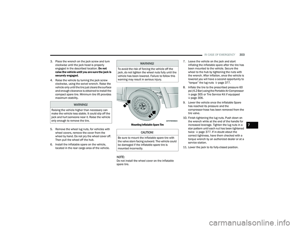
6. Install the inflatable spare on the vehicle, located in the rear cargo area of the vehicle.
Mounting Inflatable Spare Tire
NOTE:Do not install the wheel cover on the inflatable
spare tire.7. Leave the vehicle on the jack and start
inflating the inflatable spare after the tire has
been mounted to the vehicle. Secure the
wheel to the hub by tightening the nuts with
the wrench. After inflation, once the vehicle is
lowered you will have a second opportunity to
“torque” the lug nuts Ú page 377.
8. Inflate the tire to the prescribed pressure 60 psi (4.2 Bar) using the Portable Air Compressor
Úpage 305 or Tire Service Kit if equipped
Ú page 306.
9. Lower the vehicle once the inflatable Spare has reached its pressure and the
compressor-hose has been removed from the
tire valve.
10. Finish tightening the lug nuts. Push down on the wrench while at the end of the handle for
increased leverage. Tighten the lug nuts in a
star pattern until each nut has been tightened
twice Ú page 377. If in doubt about the
correct tightness, have them checked with a
torque wrench by an authorized dealer or at a
service station.
11. Lower the jack to its fully-closed position.
WARNING!
Raising the vehicle higher than necessary can
make the vehicle less stable. It could slip off the
jack and hurt someone near it. Raise the vehicle
only enough to remove the tire.
WARNING!
To avoid the risk of forcing the vehicle off the
jack, do not tighten the wheel nuts fully until the
vehicle has been lowered. Failure to follow this
warning may result in serious injury.
CAUTION!
Be sure to mount the inflatable spare tire with
the valve stem facing outward. The vehicle could
be damaged if the inflatable spare tire is
mounted incorrectly.
7
21_RUP_OM_EN_USC_t.book Page 303
Page 307 of 401
IN CASE OF EMERGENCY305
4. Install the remaining lug nuts with the cone shaped end of the nut toward the wheel.
Lightly tighten all the lug nuts until the wheel
sits flush onto the hub and there is no play. The
nuts will have to be fully tightened once the
vehicle is lowered. Tightening an improperly
seated wheel under vehicle load can damage
the threads, cause vibration, and undermine
safety.
5. Lower the vehicle to the ground by turning the jack handle counterclockwise.
6. Finish tightening the lug nuts. Push down on the wrench while at the end of the handle for
increased leverage. Tighten the lug nuts in a
star pattern until each nut has been tightened
twice Ú page 377. If in doubt about the
correct tightness, have them checked with a
torque wrench by an authorized dealer or at a
service station.
7. After 25 miles (40 km) check the lug nut torque with a torque wrench to ensure that all
lug nuts are properly seated against the wheel.
PORTABLE AIR COMPRESSOR —
I
F EQUIPPED
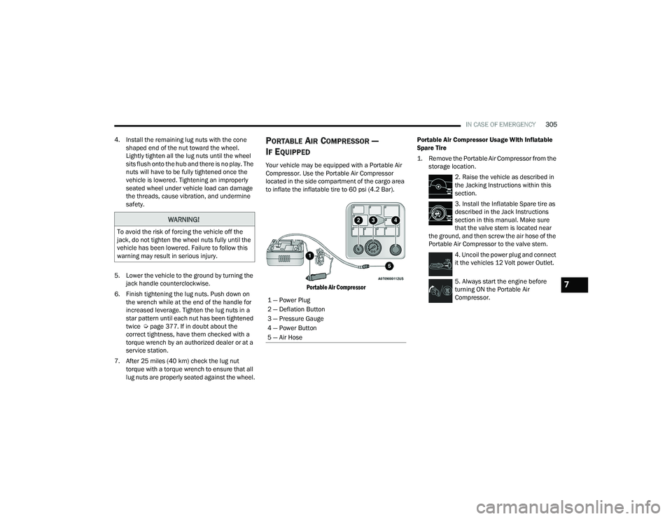
Your vehicle may be equipped with a Portable Air
Compressor. Use the Portable Air Compressor
located in the side compartment of the cargo area
to inflate the inflatable tire to 60 psi (4.2 Bar).
Portable Air Compressor
Portable Air Compressor Usage With Inflatable
Spare Tire
1. Remove the Portable Air Compressor from the
storage location.
2. Raise the vehicle as described in
the Jacking Instructions within this
section.
3. Install the Inflatable Spare tire as
described in the Jack Instructions
section in this manual. Make sure
that the valve stem is located near
the ground, and then screw the air hose of the
Portable Air Compressor to the valve stem.
4. Uncoil the power plug and connect
it the vehicles 12 Volt power Outlet.
5. Always start the engine before
turning ON the Portable Air
Compressor.
WARNING!
To avoid the risk of forcing the vehicle off the
jack, do not tighten the wheel nuts fully until the
vehicle has been lowered. Failure to follow this
warning may result in serious injury.
1 — Power Plug
2 — Deflation Button
3 — Pressure Gauge
4 — Power Button
5 — Air Hose
7
21_RUP_OM_EN_USC_t.book Page 305
Page 365 of 401
SERVICING AND MAINTENANCE363
TIRES — GENERAL INFORMATION
Tire Pressure
Proper tire inflation pressure is essential to the
safe and satisfactory operation of your vehicle.
Four primary areas are affected by improper tire
pressure:
Safety
Fuel Economy
Tread Wear
Ride Comfort and Vehicle Stability Safety
Both underinflation and overinflation affect the
stability of the vehicle and can produce a feeling of
sluggish response or over responsiveness in the
steering.
NOTE:
Unequal tire pressures from side to side may
cause erratic and unpredictable steering
response.
Unequal tire pressure from side to side may
cause the vehicle to drift left or right.
Fuel Economy
Underinflated tires will increase tire rolling
resistance resulting in higher fuel consumption.
Tread Wear
Improper cold tire inflation pressures can cause
abnormal wear patterns and reduced tread life,
resulting in the need for earlier tire replacement.
Ride Comfort And Vehicle Stability
Proper tire inflation contributes to a comfortable
ride. Overinflation produces a jarring and
uncomfortable ride.
Tire Inflation Pressures
The proper cold tire inflation pressure is listed on
the driver's side B-pillar or rear edge of the driver's
side door.
WARNING!
Overloading of your tires is dangerous.
Overloading can cause tire failure, affect vehicle
handling, and increase your stopping distance.
Use tires of the recommended load capacity for
your vehicle. Never overload them.WARNING!
Improperly inflated tires are dangerous and
can cause collisions.
Underinflation increases tire flexing and can
result in overheating and tire failure.
Overinflation reduces a tire's ability to cushion
shock. Objects on the road and chuckholes
can cause damage that result in tire failure.
Overinflated or underinflated tires can affect
vehicle handling and can fail suddenly,
resulting in loss of vehicle control.
Unequal tire pressures can cause steering
problems. You could lose control of your
vehicle.
Unequal tire pressures from one side of the
vehicle to the other can cause the vehicle to
drift to the right or left.
Always drive with each tire inflated to the
recommended cold tire inflation pressure.
8
21_RUP_OM_EN_USC_t.book Page 363
Page 380 of 401
378TECHNICAL SPECIFICATIONS
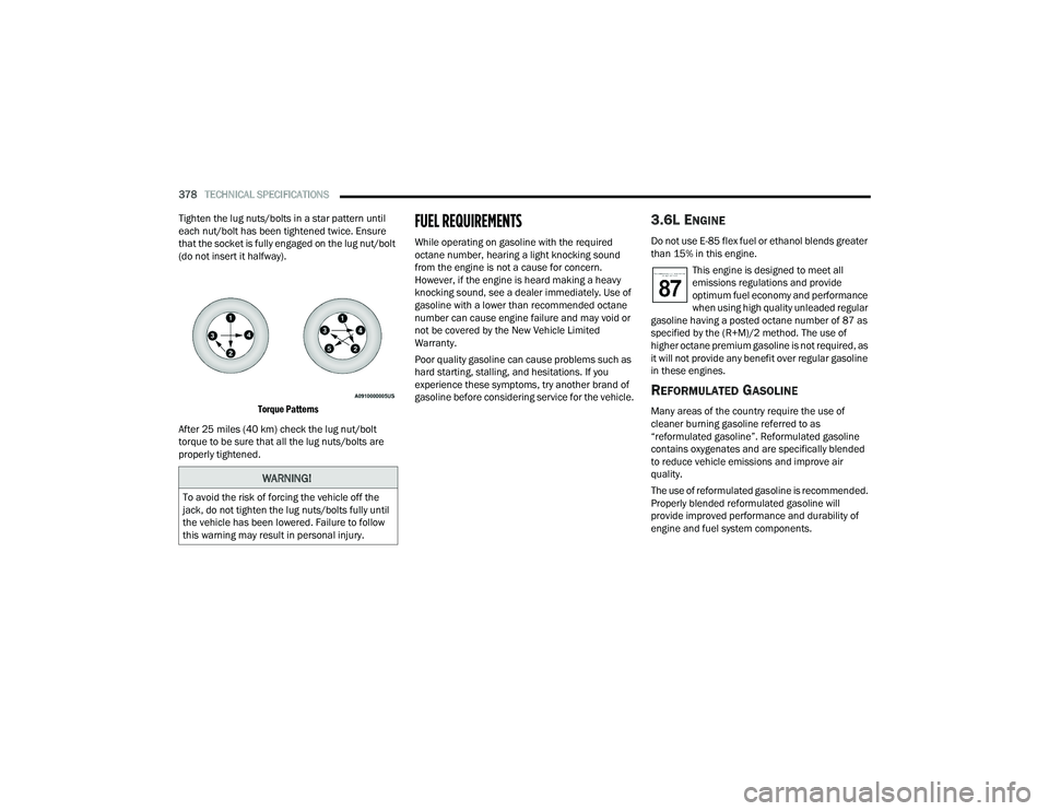
Tighten the lug nuts/bolts in a star pattern until
each nut/bolt has been tightened twice. Ensure
that the socket is fully engaged on the lug nut/bolt
(do not insert it halfway).
Torque Patterns
After 25 miles (40 km) check the lug nut/bolt
torque to be sure that all the lug nuts/bolts are
properly tightened.
FUEL REQUIREMENTS
While operating on gasoline with the required
octane number, hearing a light knocking sound
from the engine is not a cause for concern.
However, if the engine is heard making a heavy
knocking sound, see a dealer immediately. Use of
gasoline with a lower than recommended octane
number can cause engine failure and may void or
not be covered by the New Vehicle Limited
Warranty.
Poor quality gasoline can cause problems such as
hard starting, stalling, and hesitations. If you
experience these symptoms, try another brand of
gasoline before considering service for the vehicle.
3.6L ENGINE
Do not use E-85 flex fuel or ethanol blends greater
than 15% in this engine. This engine is designed to meet all
emissions regulations and provide
optimum fuel economy and performance
when using high quality unleaded regular
gasoline having a posted octane number of 87 as
specified by the (R+M)/2 method. The use of
higher octane premium gasoline is not required, as
it will not provide any benefit over regular gasoline
in these engines.
REFORMULATED GASOLINE
Many areas of the country require the use of
cleaner burning gasoline referred to as
“reformulated gasoline”. Reformulated gasoline
contains oxygenates and are specifically blended
to reduce vehicle emissions and improve air
quality.
The use of reformulated gasoline is recommended.
Properly blended reformulated gasoline will
provide improved performance and durability of
engine and fuel system components.
WARNING!
To avoid the risk of forcing the vehicle off the
jack, do not tighten the lug nuts/bolts fully until
the vehicle has been lowered. Failure to follow
this warning may result in personal injury.
21_RUP_OM_EN_USC_t.book Page 378