check engine CHRYSLER PACIFICA HYBRID 2022 Owners Manual
[x] Cancel search | Manufacturer: CHRYSLER, Model Year: 2022, Model line: PACIFICA HYBRID, Model: CHRYSLER PACIFICA HYBRID 2022Pages: 384, PDF Size: 23.92 MB
Page 9 of 384
7
JUMP STARTING................................................... 300 Preparations For Jump Start......................... 301Jump Starting Procedure .............................. 301
REFUELING IN EMERGENCY –
IF EQUIPPED ......................................................... 302
IF YOUR ENGINE OVERHEATS ............................ 303
MANUAL PARK RELEASE .................................. 304
FREEING A STUCK VEHICLE .............................. 305
TOWING A DISABLED VEHICLE .......................... 306
All Wheel Drive (AWD) Models ...................... 308
ENHANCED ACCIDENT RESPONSE SYSTEM
(EARS) .................................................................. 308
EVENT DATA RECORDER (EDR) ......................... 308
SERVICING AND MAINTENANCE
SCHEDULED SERVICING ..................................... 309
Maintenance Plan ......................................... 310
ENGINE COMPARTMENT .................................... 313
3.6L Engine.................................................... 313
Checking Oil Level ......................................... 314
Adding Washer Fluid .................................... 314
Maintenance-Free Battery ........................... 314
Pressure Washing ......................................... 315 VEHICLE MAINTENANCE..................................... 315
Engine Oil ...................................................... 315
Engine Oil Filter ............................................. 316Engine Air Cleaner Filter ............................... 316
Accessory Drive Belt Inspection ................... 317Air Conditioner Maintenance........................ 317
Body Lubrication ........................................... 320Windshield Wiper Blades.............................. 320Exhaust System ............................................ 323
Cooling System .............................................. 324
Brake System ............................................... 327
Automatic Transmission .............................. 328Fuses.............................................................. 329
Bulb Replacement......................................... 337
TIRES ................................................................... 339
Tire Safety Information ................................. 339
Tires — General Information ......................... 346
Tire Types....................................................... 350
Spare Tires — If Equipped ............................ 350
Wheel And Wheel Trim Care ........................ 352
Snow Traction Devices ................................. 353
Tire Rotation Recommendations ................. 355 DEPARTMENT OF TRANSPORTATION
UNIFORM TIRE QUALITY GRADES .................... 355
Treadwear...................................................... 356
Traction Grades ............................................. 356Temperature Grades..................................... 356
STORING THE VEHICLE ....................................... 357
BODYWORK .......................................................... 357
Protection From Atmospheric Agents ......... 357
Body And Underbody Maintenance ............. 357
Preserving The Bodywork ............................. 357
INTERIORS ........................................................... 358
Seats And Fabric Parts ................................. 358
Plastic And Coated Parts .............................. 359
Leather Surfaces........................................... 359
Glass Surfaces ............................................. 359TECHNICAL SPECIFICATIONS
VEHICLE IDENTIFICATION NUMBER
(VIN) ....................................................................... 360
BRAKE SYSTEM ................................................... 360
WHEEL AND TIRE TORQUE
SPECIFICATIONS .................................................. 360Torque Specifications ................................... 360
22_RUP_OM_EN_USC_t.book Page 7
Page 14 of 384
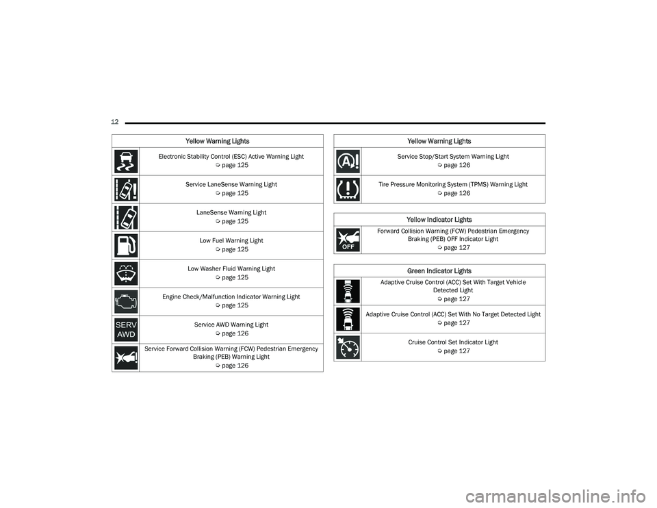
12 Electronic Stability Control (ESC) Active Warning Light Úpage 125
Service LaneSense Warning Light Úpage 125
LaneSense Warning Light Úpage 125
Low Fuel Warning Light Úpage 125
Low Washer Fluid Warning Light Úpage 125
Engine Check/Malfunction Indicator Warning Light Úpage 125
Service AWD Warning Light Úpage 126
Service Forward Collision Warning (FCW) Pedestrian Emergency Braking (PEB) Warning Light
Úpage 126
Yellow Warning Lights
Service Stop/Start System Warning Light
Úpage 126
Tire Pressure Monitoring System (TPMS) Warning Light Úpage 126
Yellow Indicator Lights
Forward Collision Warning (FCW) Pedestrian Emergency
Braking (PEB) OFF Indicator Light
Úpage 127
Green Indicator Lights
Adaptive Cruise Control (ACC) Set With Target Vehicle
Detected Light
Ú page 127
Adaptive Cruise Control (ACC) Set With No Target Detected Light Úpage 127
Cruise Control Set Indicator Light Úpage 127
Yellow Warning Lights
22_RUP_OM_EN_USC_t.book Page 12
Page 17 of 384
GETTING TO KNOW YOUR VEHICLE15
In case the ignition switch does not change with
the push of a button, the key fob may have a low or
fully depleted battery. A low key fob battery can be
verified by referring to the instrument cluster,
which will display directions to follow.
NOTE:
A low key fob battery condition may be indicated
by a message in the instrument cluster display,
or by the LED light on the key fob. If the LED key
fob light no longer illuminates from key fob
button pushes, then the key fob battery requires
replacement.
The key fob LED light brightness is designed for
indoor light viewing, so the LED light may not be
visible in direct sunlight Ú page 370.
To Lock/Unlock The Doors And Liftgate
Push and release the unlock button on the key fob
once to unlock the driver’s front door and sliding door
or twice within five seconds to unlock all doors and
the liftgate. Push and release the lock button on the
key fob to lock all doors and the liftgate.
When the doors are unlocked, the turn signals will
flash and the illuminated entry system will be
activated. When the doors are locked, the turn
signals will flash and the horn will chirp. Settings in
the Uconnect system can change to lights only,
chirp only, or both. Vehicles Equipped With Keyless Enter ‘n Go™ —
Passive Entry
If one or more doors are open, or the liftgate is
open, the doors can be locked. The doors will
unlock again only if the key fob is inside the
passenger compartment.
All doors can be programmed to unlock on the first
push of the unlock button within Uconnect Settings
Ú
page 188.
Key Left Vehicle Feature
If a valid key fob is no longer detected inside the
vehicle while the vehicle’s ignition system is in the
ON/RUN or START position, the message “Key Fob
Has Left The Vehicle” will be shown in the
instrument cluster display along with an interior
chime. An exterior audible and visual alert will also
be activated to warn the driver.
The vehicle’s horn will rapidly chirp three times along
with a single flash of the vehicle’s exterior lights.
NOTE:
The doors have to be open and then closed in
order for the vehicle to check for the presence of
a key fob; the Key Left Vehicle feature will not
activate until all of the doors are closed.
These alerts will not be activated in situations
where the vehicle’s engine is left running with
the key fob inside.
Replacing The Battery In The Key Fob
The recommended replacement battery is one
CR2032 battery.
NOTE:
Customers are recommended to use a battery
obtained from Mopar®. Aftermarket coin
battery dimensions may not meet the original
OEM coin battery dimensions.
Batteries contain harmful chemicals. Dispose
old batteries by placing them in correct
containers according to the law or by taking
them to a dealership, where they will be handled
appropriately.
Perchlorate Material — special handling may
apply. See www.dtsc.ca.gov/hazard -
ouswaste/perchlorate for further information.
Do not touch the battery terminals that are on
the back housing or the printed circuit board.
2
22_RUP_OM_EN_USC_t.book Page 15
Page 19 of 384
GETTING TO KNOW YOUR VEHICLE17
KeySense Features — If Equipped
This feature provides the vehicle owner with the
ability to customize vehicle settings that can be
applied to determine the driving experience for
other drivers of the vehicle. The vehicle settings
are protected by a unique 4-digit PIN, which the
vehicle owner creates when accessing the specific
settings for the first time.
KeySense also has additional features that are
always enabled when the specific key is in use that
cannot be set by the vehicle owner. While this
specific key fob is in use, the vehicle will respond
accordingly to the customized vehicle settings and
mandatory features. This includes enhanced
driving assistance features, increased driver
alerts, and the locking of certain optional features.
These settings can be selected within the
Uconnect system Úpage 188.
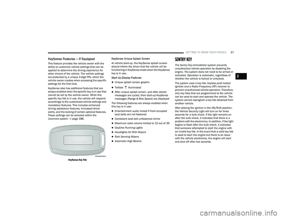
KeySense Key Fob
KeySense Unique Splash Screen
At vehicle start-up, the KeySense splash screen
should inform the driver that the vehicle will be
functioning in KeySense mode when the KeySense
key is in use.
Start Up Display Features
Unique splash screen graphic
Telltale illuminated
After unique splash screen, and after stored
messages are cycled, then start-up KeySense
messages (Range & Max Speed) are displayed
The following features are always enabled when
this key is in use:
Entertainment audio muted if front occupied
seat belts are not fastened
Consistent seat belt unfastened chime
Maximum radio volume limited to 15 out of 39
Daytime Running Lights
Headlights On With Wipers
Rain Sensing Wipers
Automatic High Beams
SENTRY KEY
The Sentry Key Immobilizer system prevents
unauthorized vehicle operation by disabling the
engine. The system does not need to be armed or
activated. Operation is automatic, regardless of
whether the vehicle is locked or unlocked.
The system uses a key fob, keyless push button
ignition and a Radio Frequency (RF) receiver to
prevent unauthorized vehicle operation. Therefore,
only key fobs that are programmed to the vehicle
can be used to start and operate the vehicle. The
system cannot reprogram a key fob obtained from
another vehicle.
After placing the ignition in the ON/RUN position,
the Vehicle Security Light will turn on for three
seconds for a bulb check. If the light remains on
after the bulb check, it indicates that there is a
problem with the electronics. In addition, if the light
begins to flash after the bulb check, it indicates
that someone attempted to start the engine with
an invalid key fob. In the event that a valid key fob
is used to start the engine but there is an issue
with the vehicle electronics, the engine will start
and shut off after two seconds.
2
22_RUP_OM_EN_USC_t.book Page 17
Page 98 of 384
96GETTING TO KNOW YOUR VEHICLE
IGNITION OFF OPERATION
The power sunroof switch will remain active for up
to approximately 10 minutes after the ignition
switch is placed in the OFF position. Opening either
front door will cancel this feature.
NOTE:Ignition off time is programmable through the
Uconnect system Úpage 188.
SUNROOF MAINTENANCE
Use only a non-abrasive cleaner and a soft cloth to
clean the glass panel. Periodically check for and
clear out any debris that may have collected in the
tracks.
HOOD
OPENING
If applicable, refer to the “Hybrid Supplement” for
additional information.
The hood release lever (to open the primary latch)
and safety latch (to open the secondary latch)
must be released to open the hood.
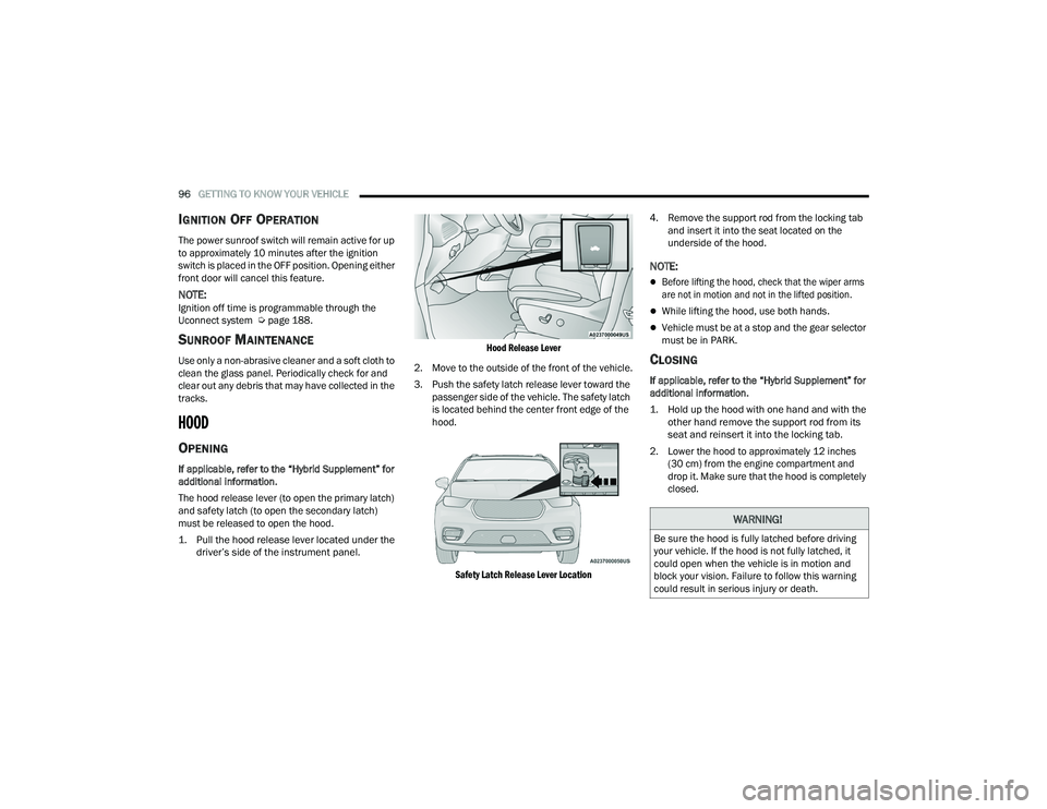
1. Pull the hood release lever located under the
driver’s side of the instrument panel.
Hood Release Lever
2. Move to the outside of the front of the vehicle.
3. Push the safety latch release lever toward the passenger side of the vehicle. The safety latch
is located behind the center front edge of the
hood.
Safety Latch Release Lever Location
4. Remove the support rod from the locking tab
and insert it into the seat located on the
underside of the hood.
NOTE:
Before lifting the hood, check that the wiper arms
are not in motion and not in the lifted position.
While lifting the hood, use both hands.
Vehicle must be at a stop and the gear selector
must be in PARK.
CLOSING
If applicable, refer to the “Hybrid Supplement” for
additional information.
1. Hold up the hood with one hand and with the other hand remove the support rod from its
seat and reinsert it into the locking tab.
2. Lower the hood to approximately 12 inches (30 cm) from the engine compartment and
drop it. Make sure that the hood is completely
closed.
WARNING!
Be sure the hood is fully latched before driving
your vehicle. If the hood is not fully latched, it
could open when the vehicle is in motion and
block your vision. Failure to follow this warning
could result in serious injury or death.
22_RUP_OM_EN_USC_t.book Page 96
Page 103 of 384

GETTING TO KNOW YOUR VEHICLE101
(Continued)
IMPORTANT SAFETY INSTRUCTIONS
Read all instructions before using. When using
your vacuum, basic precautions should be
followed, including the following:
WARNING!
Never leave children alone in a vehicle, or
with access to an unlocked vehicle. Allowing
children to be in a vehicle unattended is
dangerous for a number of reasons. A child or
others could be seriously or fatally injured.
Children should be warned not to touch the
parking brake, brake pedal or the gear
selector.
Do not leave the key fob in or near the vehicle,
or in a location accessible to children, and do
not leave the Keyless Enter ‘n Go™ Ignition in
either the ACC position, or engine running
(ON), unless you are using the vacuum
system. Be aware a child could operate power
windows, other controls, or move the vehicle
when the vacuum system is in use. ALWAYS
push ignition button to place ignition in the
OFF position when finished using the vacuum
system.
WARNING!
To reduce the risk of fire, serious injury or death:
Do not use vacuum while vehicle is
in motion or while driving.
Do not vacuum wet surfaces or any liquids.
Do not use to vacuum up anything outside of
the vehicle.
Do not vacuum any flammable
liquids, such as gasoline, or use
around explosive vapors. Vapors
from flammable liquids may form an
explosive mixture with air and can be ignited
by heat, sparks, or flames. Vapors may travel
to a source of ignition and explode.
Do not vacuum anything that is burning or
smoking, such as cigarettes, matches, or hot
ashes/embers.
Do not allow to be used as a toy. Close atten -
tion is necessary when used by or near chil -
dren.
Do not leave the vacuum running while unat -
tended.
Use only as described in this manual. Use only
attachments provided with your vehicle.
Do not put any object into openings. Do not
use with any opening blocked; keep free of
dust, lint, hair, and anything that may reduce
air flow.
Do not vacuum toxic material such as chlorine
bleach, ammonia, drain cleaner, etc.
Do not vacuum hard or sharp objects such as
glass, nails, screws, coins, etc.
Keep hair, loose clothing, fingers, and all parts
of body away from openings and moving parts.
Only use with filter in place. Periodically check
that the filter is in place and in good condition.
WARNING!
This equipment incorporates parts such as
switches, motors, or the like that tend to
produce arcs or sparks that can cause an
explosion. When using your vacuum near
gasoline-dispensing equipment or service
stations, park vehicle at least 20 ft (6 m) away
from the exterior enclosure of any dispensing
pump. The vacuum is mounted more than
18 inches (45 cm) above ground level in your
vehicle.
WARNING!
2
22_RUP_OM_EN_USC_t.book Page 101
Page 106 of 384

104GETTING TO KNOW YOUR VEHICLE
5. When finished, push power button to turn vacuum off and store vacuum hose and any
attachments. 6. Before exiting the vehicle:
If the ignition is in the ACC position, push
the START/STOP ignition button to place
ignition in the OFF position, remove key fob
from the vehicle, and lock the vehicle.
If the engine is running, raise all of the
windows, push the START/STOP ignition
button to place ignition in the OFF position,
remove key fob from the vehicle, close all of
the doors and the liftgate and lock the
vehicle.
Vacuum Troubleshooting
DO NOT use with any opening blocked. If an
object becomes lodged in the hose, attempt to
fully extend the hose in a straight line while the
vacuum motor is running. If this does not
dislodge the object, turn the vacuum OFF and
remove the hose from the vehicle using the
subsequent removal instructions. If the filter is
clogged, follow the emptying debris bin proce -
dure and lightly tap the filter on the collection
bin to remove any collected debris from the
filter. Both the bin and the filter can be rinsed
with water if needed. To avoid mold and stale
odors, allow both to dry completely before rein -
stalling in your vehicle. If the filter has tears,
holes or other damage and needs to be
replaced, please contact an authorized dealer.
If there are any other issues with your vacuum,
contact an authorized dealer. Your vacuum has
no user serviceable parts.
Debris Bin
The debris bin is located behind the access panel
behind the third row seat on the driver’s side.
To Empty
1. Push power button to turn vacuum OFF.
2. Open the access panel by pulling the finger grip towards you and then pull downward.
Vacuum System Access Panel
Do not vacuum toxic material such as chlorine
bleach, ammonia, drain cleaner, etc.
Do not vacuum hard or sharp objects such as
glass, nails, screws, coins, etc.
Keep hair, loose clothing, fingers, and all parts
of body away from openings and moving parts.
Only use with filter in place. Periodically check
that the filter is in place and in good condition.
WARNING!
This equipment incorporates parts such as
switches, motors, or the like that tend to
produce arcs or sparks that can cause an
explosion. When using your vacuum near
gasoline-dispensing equipment or service
stations, park vehicle at least 20 ft (6 m) away
from the exterior enclosure of any dispensing
pump. The vacuum is mounted more than
18 inches (45 cm) above ground level in your
vehicle.
WARNING!
22_RUP_OM_EN_USC_t.book Page 104
Page 114 of 384
112GETTING TO KNOW YOUR INSTRUMENT PANEL
INSTRUMENT CLUSTER DESCRIPTIONS
1. Tachometer
Indicates the engine speed in revolutions
per minute (RPM x 1000).
2. Instrument Cluster Display
When the appropriate conditions exist, this
display shows the instrument cluster
display messages Ú page 113.
The display shows one of the main menu
items after the ignition is turned/placed on.
3. Speedometer
Indicates vehicle speed.
4. Temperature Gauge
The temperature gauge shows engine
coolant temperature. Any reading within the
normal range indicates that the engine
cooling system is operating satisfactorily.
The gauge can indicate a higher tempera -
ture when driving in hot weather or up
mountain grades. It should not be allowed
to exceed the upper limits of the normal
operating range. 5. Fuel GaugeThe gauge shows the level of fuel in the
fuel tank when the ignition switch is in the
ON/RUN position.
The fuel pump symbol points to
the side of the vehicle where the
fuel door is located.
NOTE:The hard telltales will illuminate for a bulb check
when the ignition is first cycled.
INSTRUMENT CLUSTER DISPLAY
Your vehicle is equipped with an instrument cluster
display, which offers useful information to the
driver. With the ignition in the OFF position (and the
key removed, for vehicles with mechanical key),
opening/closing of a door will activate the display
for viewing, and display the total miles or
kilometers in the odometer. Your instrument
cluster display is designed to display important
information about your vehicle’s systems and
features. Using a driver interactive display located
on the instrument panel, your instrument cluster
display can show you how systems are working and
give you warnings when they are not. The steering
wheel mounted controls allow you to scroll through
and enter the main menus and submenus. You can
access the specific information you want and
make selections and adjustments.
WARNING!
Driving with a hot engine cooling system could
damage your vehicle. If the temperature gauge
reaches “H” pull over and stop the vehicle. Idle
the vehicle with the air conditioner turned off
until the gauge drops back into the normal range
and is no longer red. If the gauge remains on the
“H”, turn the engine off immediately and call an
authorized dealer for service.
WARNING!
A hot engine cooling system is dangerous. You or
others could be badly burned by steam or boiling
coolant. You may want to call an authorized
dealer for service if your vehicle overheats
Ú page 324.
22_RUP_OM_EN_USC_t.book Page 112
Page 122 of 384
120GETTING TO KNOW YOUR INSTRUMENT PANEL
NOTE:
The charging system is independent from load
reduction. The charging system performs a diag-
nostic on the charging system continuously.
If the Battery Charge Warning Light is on it may
indicate a problem with the charging system
Ú page 121.
The electrical loads that may be switched off (if
equipped), and vehicle functions which can be
effected by load reduction:
Heated Seat/Vented Seats/Heated Wheel
Heated/Cooled Cup Holders — If Equipped
Rear Defroster And Heated Mirrors
HVAC System
115 Volts AC Power Inverter System
Audio and Telematics System
Loss of the battery charge may indicate one or
more of the following conditions:
The charging system cannot deliver enough
electrical power to the vehicle system because
the electrical loads are larger than the capability
of charging system. The charging system is still
functioning properly.
Turning on all possible vehicle electrical loads
(e.g. HVAC to max settings, exterior and interior
lights, overloaded power outlets +12 Volts,
150W, USB ports) during certain driving condi -
tions (city driving, towing, frequent stopping).
Installing options like additional lights, upfitter
electrical accessories, audio systems, alarms
and similar devices.
Unusual driving cycles (short trips separated by
long parking periods).
The vehicle was parked for an extended period
of time (weeks, months).
The battery was recently replaced and was not
charged completely.
The battery was discharged by an electrical load
left on when the vehicle was parked.
The battery was used for an extended period
with the engine not running to supply radio,
lights, chargers, +12 Volt portable appliances
like vacuum cleaners, game consoles and
similar devices. What to do when an electrical load reduction
action message is present (“Battery Saver On” or
“Battery Saver Mode”)
During a trip:
Reduce power to unnecessary loads if possible:
Turn off redundant lights (interior or exterior)
Check what may be plugged in to power
outlets +12 Volts, 150W, USB ports
Check HVAC settings (blower, temperature)
Check the audio settings (volume)
After a trip:
Check if any aftermarket equipment was
installed (additional lights, upfitter electrical
accessories, audio systems, alarms) and review
specifications if any (load and Ignition Off Draw
currents).
Evaluate the latest driving cycles (distance,
driving time and parking time).
The vehicle should have service performed if
the message is still present during consecutive
trips and the evaluation of the vehicle and
driving pattern did not help to identify the cause.
22_RUP_OM_EN_USC_t.book Page 120
Page 123 of 384
GETTING TO KNOW YOUR INSTRUMENT PANEL121
TRIP COMPUTER
The Trip Computer is located in the instrument
cluster display. Push and release the up or
down arrow button until “Trip Info” is
highlighted in the instrument cluster display.
Navigate between Trip A or Trip B by using the
right and left arrow buttons.
For each trip the following information will be
displayed:
Trip A
Shows the total distance traveled for Trip A
since the last reset.
Shows the Average MPG for Trip A since the last
reset.
Shows the elapsed time traveled for Trip A since
the last reset. Elapsed time will increment when
the ignition switch is in the ON or START position.
Trip B
Shows the total distance traveled for Trip B
since the last reset.
Shows the Average MPG for Trip B since the last
reset.
Shows the elapsed time traveled for Trip B since
the last reset. Elapsed time will increment when
the ignition switch is in the ON or START position.
To Reset A Trip Function
Push and hold the OK button to reset the currently
displayed trip.
WARNING LIGHTS AND MESSAGES
The warning/indicator lights will illuminate in the
instrument panel together with a dedicated
message and/or acoustic signal when applicable.
These indications are indicative and precautionary
and as such must not be considered as exhaustive
and/or alternative to the information contained in
the Owner’s Manual, which you are advised to read
carefully in all cases. Always refer to the
information in this chapter in the event of a failure
indication. All active telltales will display first if
applicable. The system check menu may appear
different based upon equipment options and
current vehicle status. Some telltales are optional
and may not appear.
RED WARNING LIGHTS
Air Bag Warning Light
This warning light will illuminate to
indicate a fault with the air bag, and will
turn on for four to eight seconds as a bulb
check when the ignition is placed in the
ON/RUN or ACC/ON/RUN position. This light will
illuminate with a single chime when a fault with the
air bag has been detected, it will stay on until the
fault is cleared. If the light is either not on during
startup, stays on, or turns on while driving, have
the system inspected at an authorized dealer as
soon as possible.
Battery Charge Warning Light
This warning light will illuminate when
the battery is not charging properly. If it
stays on while the engine is running,
there may be a malfunction with the
charging system. Contact an authorized dealer as
soon as possible.
This indicates a possible problem with the
electrical system or a related component.
3
22_RUP_OM_EN_USC_t.book Page 121