engine overheat CHRYSLER PACIFICA HYBRID 2022 Owners Manual
[x] Cancel search | Manufacturer: CHRYSLER, Model Year: 2022, Model line: PACIFICA HYBRID, Model: CHRYSLER PACIFICA HYBRID 2022Pages: 384, PDF Size: 23.92 MB
Page 9 of 384
7
JUMP STARTING................................................... 300 Preparations For Jump Start......................... 301Jump Starting Procedure .............................. 301
REFUELING IN EMERGENCY –
IF EQUIPPED ......................................................... 302
IF YOUR ENGINE OVERHEATS ............................ 303
MANUAL PARK RELEASE .................................. 304
FREEING A STUCK VEHICLE .............................. 305
TOWING A DISABLED VEHICLE .......................... 306
All Wheel Drive (AWD) Models ...................... 308
ENHANCED ACCIDENT RESPONSE SYSTEM
(EARS) .................................................................. 308
EVENT DATA RECORDER (EDR) ......................... 308
SERVICING AND MAINTENANCE
SCHEDULED SERVICING ..................................... 309
Maintenance Plan ......................................... 310
ENGINE COMPARTMENT .................................... 313
3.6L Engine.................................................... 313
Checking Oil Level ......................................... 314
Adding Washer Fluid .................................... 314
Maintenance-Free Battery ........................... 314
Pressure Washing ......................................... 315 VEHICLE MAINTENANCE..................................... 315
Engine Oil ...................................................... 315
Engine Oil Filter ............................................. 316Engine Air Cleaner Filter ............................... 316
Accessory Drive Belt Inspection ................... 317Air Conditioner Maintenance........................ 317
Body Lubrication ........................................... 320Windshield Wiper Blades.............................. 320Exhaust System ............................................ 323
Cooling System .............................................. 324
Brake System ............................................... 327
Automatic Transmission .............................. 328Fuses.............................................................. 329
Bulb Replacement......................................... 337
TIRES ................................................................... 339
Tire Safety Information ................................. 339
Tires — General Information ......................... 346
Tire Types....................................................... 350
Spare Tires — If Equipped ............................ 350
Wheel And Wheel Trim Care ........................ 352
Snow Traction Devices ................................. 353
Tire Rotation Recommendations ................. 355 DEPARTMENT OF TRANSPORTATION
UNIFORM TIRE QUALITY GRADES .................... 355
Treadwear...................................................... 356
Traction Grades ............................................. 356Temperature Grades..................................... 356
STORING THE VEHICLE ....................................... 357
BODYWORK .......................................................... 357
Protection From Atmospheric Agents ......... 357
Body And Underbody Maintenance ............. 357
Preserving The Bodywork ............................. 357
INTERIORS ........................................................... 358
Seats And Fabric Parts ................................. 358
Plastic And Coated Parts .............................. 359
Leather Surfaces........................................... 359
Glass Surfaces ............................................. 359TECHNICAL SPECIFICATIONS
VEHICLE IDENTIFICATION NUMBER
(VIN) ....................................................................... 360
BRAKE SYSTEM ................................................... 360
WHEEL AND TIRE TORQUE
SPECIFICATIONS .................................................. 360Torque Specifications ................................... 360
22_RUP_OM_EN_USC_t.book Page 7
Page 33 of 384
GETTING TO KNOW YOUR VEHICLE31
STEERING WHEEL
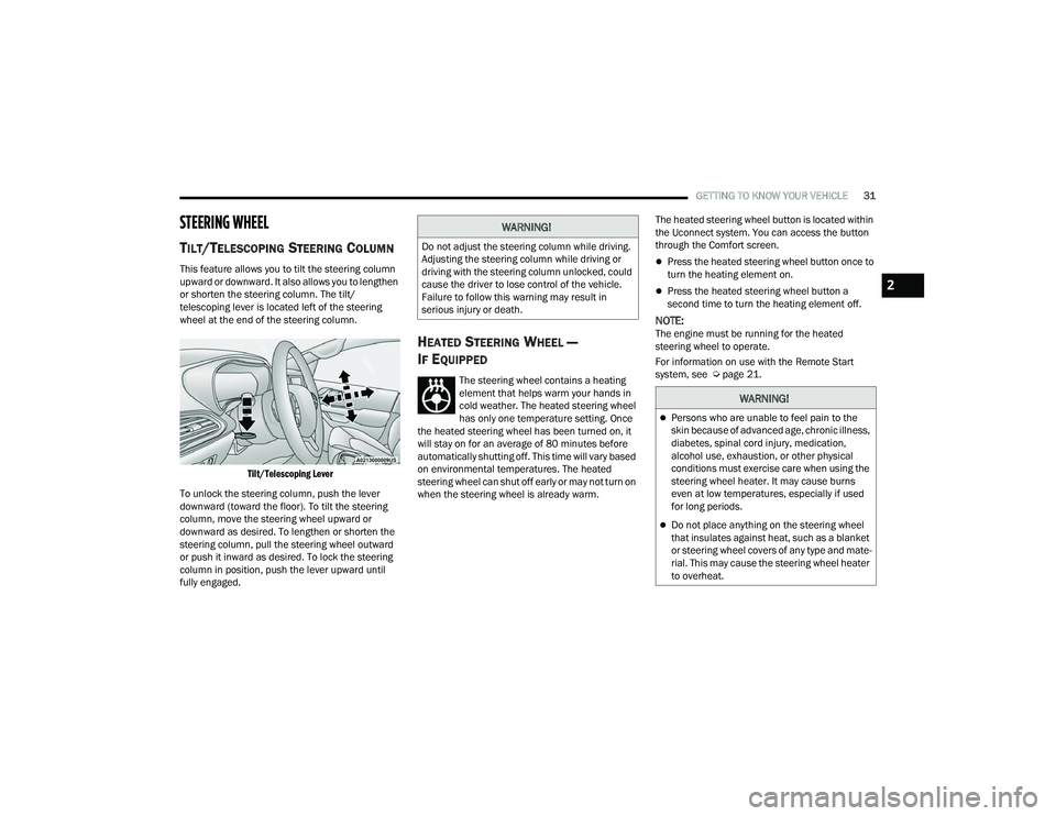
TILT/TELESCOPING STEERING COLUMN
This feature allows you to tilt the steering column
upward or downward. It also allows you to lengthen
or shorten the steering column. The tilt/
telescoping lever is located left of the steering
wheel at the end of the steering column.
Tilt/Telescoping Lever
To unlock the steering column, push the lever
downward (toward the floor). To tilt the steering
column, move the steering wheel upward or
downward as desired. To lengthen or shorten the
steering column, pull the steering wheel outward
or push it inward as desired. To lock the steering
column in position, push the lever upward until
fully engaged.
HEATED STEERING WHEEL —
I
F EQUIPPED
The steering wheel contains a heating
element that helps warm your hands in
cold weather. The heated steering wheel
has only one temperature setting. Once
the heated steering wheel has been turned on, it
will stay on for an average of 80 minutes before
automatically shutting off. This time will vary based
on environmental temperatures. The heated
steering wheel can shut off early or may not turn on
when the steering wheel is already warm. The heated steering wheel button is located within
the Uconnect system. You can access the button
through the Comfort screen.
Press the heated steering wheel button once to
turn the heating element on.
Press the heated steering wheel button a
second time to turn the heating element off.
NOTE:The engine must be running for the heated
steering wheel to operate.
For information on use with the Remote Start
system, see Ú
page 21.
WARNING!
Do not adjust the steering column while driving.
Adjusting the steering column while driving or
driving with the steering column unlocked, could
cause the driver to lose control of the vehicle.
Failure to follow this warning may result in
serious injury or death.
WARNING!
Persons who are unable to feel pain to the
skin because of advanced age, chronic illness,
diabetes, spinal cord injury, medication,
alcohol use, exhaustion, or other physical
conditions must exercise care when using the
steering wheel heater. It may cause burns
even at low temperatures, especially if used
for long periods.
Do not place anything on the steering wheel
that insulates against heat, such as a blanket
or steering wheel covers of any type and mate -
rial. This may cause the steering wheel heater
to overheat.
2
22_RUP_OM_EN_USC_t.book Page 31
Page 53 of 384
GETTING TO KNOW YOUR VEHICLE51
4. The third row power seat system includes obstacle detection. When the system detects
an obstacle, the motors will stop and reverse
direction. Should this occur, remove the
obstacle before pushing the button again.
HEATED SEATS
Front Heated Seats — If Equipped
The front heated seats control buttons
are located in the touchscreen.
You can choose from HI, LO or off heat settings.
The indicator lights in each switch indicate the
level of heat in use. Two indicator lights will
illuminate for HI, one for LO and none for off.
Press the heated seat button once to turn the
HI setting on.
Press the heated seat button a second time to
turn the LO setting on.
Press the heated seat button a third time to turn
the heating elements off.
The level of heat selected will stay on until the
operator changes it.
NOTE:
Once a heat setting is selected, heat will be felt
within two to five minutes.
The engine must be running for the heated
seats to operate. For information on use with the Remote Start
system, see Ú
page 21.
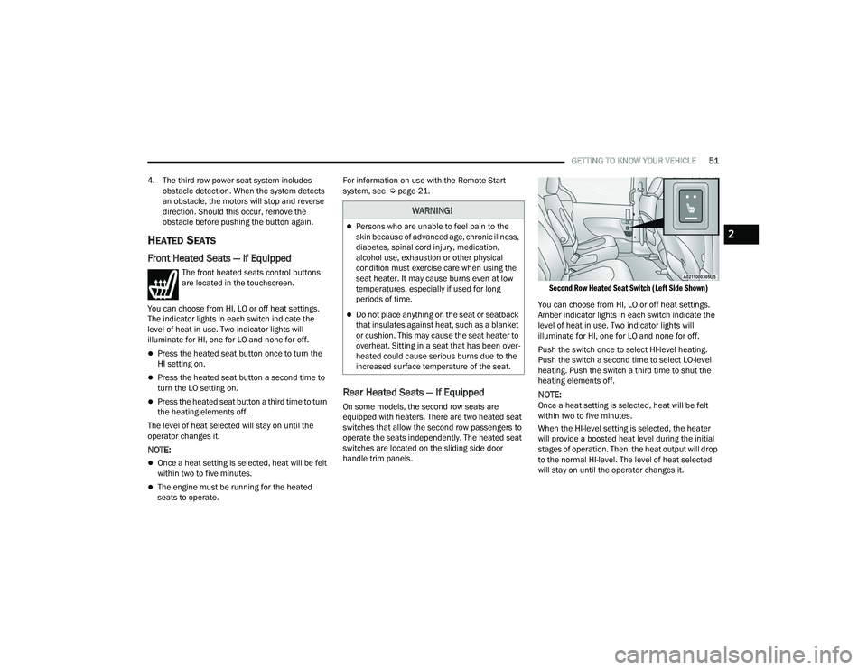
Rear Heated Seats — If Equipped
On some models, the second row seats are
equipped with heaters. There are two heated seat
switches that allow the second row passengers to
operate the seats independently. The heated seat
switches are located on the sliding side door
handle trim panels.
Second Row Heated Seat Switch (Left Side Shown)
You can choose from HI, LO or off heat settings.
Amber indicator lights in each switch indicate the
level of heat in use. Two indicator lights will
illuminate for HI, one for LO and none for off.
Push the switch once to select HI-level heating.
Push the switch a second time to select LO-level
heating. Push the switch a third time to shut the
heating elements off.
NOTE:Once a heat setting is selected, heat will be felt
within two to five minutes.
When the HI-level setting is selected, the heater
will provide a boosted heat level during the initial
stages of operation. Then, the heat output will drop
to the normal HI-level. The level of heat selected
will stay on until the operator changes it.
WARNING!
Persons who are unable to feel pain to the
skin because of advanced age, chronic illness,
diabetes, spinal cord injury, medication,
alcohol use, exhaustion or other physical
condition must exercise care when using the
seat heater. It may cause burns even at low
temperatures, especially if used for long
periods of time.
Do not place anything on the seat or seatback
that insulates against heat, such as a blanket
or cushion. This may cause the seat heater to
overheat. Sitting in a seat that has been over -
heated could cause serious burns due to the
increased surface temperature of the seat.
2
22_RUP_OM_EN_USC_t.book Page 51
Page 65 of 384
GETTING TO KNOW YOUR VEHICLE63
2. Push the programmed HomeLink® button to confirm that the garage door opener motor
operates. If the garage door opener motor
does not operate, repeat the steps from the
beginning.
PROGRAMMING HOMELINK® TO A
M
ISCELLANEOUS DEVICE
The procedure on how to program HomeLink® to a
miscellaneous device follows the same procedure
as programming to a garage door opener
Ú page 62. Be sure to determine if the device has
a rolling code, or non-rolling code before beginning
the programming process.
NOTE:Canadian Radio Frequency (RF) laws require trans -
mitter signals to time-out (or quit) after several
seconds of transmission, which may not be long
enough for HomeLink® to pick up the signal during
programming. Similar to this Canadian law, some
U.S. gate operators are designed to time-out in the
same manner. The procedure may need to be
performed multiple times to successfully pair the
device to your HomeLink® buttons.
REPROGRAMMING A SINGLE
H
OMELINK® BUTTON
To reprogram a single HomeLink® button that has
been previously trained, without erasing all the
channels, proceed as follows. Be sure to
determine whether the new device you want to
program the HomeLink® button to has a rolling
code, or non-rolling code.
1. Place the ignition in the ON/RUN position,
without starting the engine.
2. Push and hold the desired HomeLink® button until the HomeLink® indicator light begins to
flash after 20 seconds. Do not release the
button.
3. Without releasing the button , proceed with
Step 2 in “Programming HomeLink® To A
Garage Door Opener” and follow all remaining
steps.
CANADIAN/GATE OPERATOR
P
ROGRAMMING
For programming transmitters in Canada/United
States that require the transmitter signals to
“time-out” after several seconds of transmission:
Canadian Radio Frequency (RF) laws require
transmitter signals to time-out (or quit) after
several seconds of transmission, which may not be
long enough for HomeLink® to pick up the signal
during programming. Similar to this Canadian law,
some U.S. gate operators are designed to time-out
in the same manner.
It may be helpful to unplug the device during the
cycling process to prevent possible overheating of
the garage door or gate motor.
1. Place the ignition in the ON/RUN position.
NOTE:For vehicles equipped with Keyless Enter ‘n Go™,
place the ignition in the RUN position. Make sure
while programming HomeLink® with the engine on
that your vehicle is outside of your garage, or that
the garage door remains open at all times.
2. Place the hand-held transmitter 1 to 3 inches
(3 to 8 cm) away from the HomeLink® button
you wish to program while keeping the
HomeLink® indicator light in view.
WARNING!
Your motorized door or gate will open and
close while you are programming the universal
transmitter. Do not program the transmitter if
people or pets are in the path of the door or
gate.
Do not run your vehicle in a closed garage or
confined area while programming the trans -
mitter. Exhaust gas from your vehicle contains
Carbon Monoxide (CO) which is odorless and
colorless. Carbon Monoxide is poisonous
when inhaled and can cause you and others to
be severely injured or killed.
2
22_RUP_OM_EN_USC_t.book Page 63
Page 85 of 384
GETTING TO KNOW YOUR VEHICLE83
CLIMATE VOICE COMMANDS
Adjust vehicle temperatures hands-free and keep
everyone comfortable while you keep moving
ahead. (If vehicle is equipped with climate control.)
Push the VR button on the steering wheel. After the
beep, say one of the following commands:
“Set driver temperature to 70 degrees ”
“Set passenger temperature to 70 degrees ”
Did you know : Voice Command for Climate may only
be used to adjust the interior temperature of your
vehicle. Voice Command will not work to adjust the
heated seats or steering wheel if equipped.
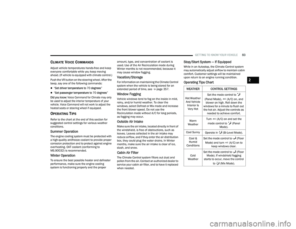
OPERATING TIPS
Refer to the chart at the end of this section for
suggested control settings for various weather
conditions.
Summer Operation
The engine cooling system must be protected with
a high-quality antifreeze coolant to provide proper
corrosion protection and to protect against engine
overheating. OAT coolant (conforming to
MS.90032) is recommended.
Winter Operation
To ensure the best possible heater and defroster
performance, make sure the engine cooling
system is functioning properly and the proper amount, type, and concentration of coolant is
used. Use of the Air Recirculation mode during
Winter months is not recommended, because it
may cause window fogging.
Vacation/Storage
For information on maintaining the Climate Control
system when the vehicle is being stored for an
extended period of time, see Ú
page 357.
Window Fogging
Vehicle windows tend to fog on the inside in mild,
rainy, and/or humid weather. To clear the
windows, select Defrost or Mix mode and increase
the front blower speed. Do not use the
Recirculation mode without A/C for long periods,
as fogging may occur.
Outside Air Intake
Make sure the air intake, located directly in front of
the windshield, is free of obstructions, such as
leaves. Leaves collected in the air intake may
reduce airflow, and if they enter the air distribution
box, they could plug the water drains. In Winter
months, make sure the air intake is clear of ice,
slush, and snow.
Cabin Air Filter
The Climate Control system filters out dust and
pollen from the air. Contact an authorized dealer to
service your cabin air filter, and to have it replaced
when needed.
Stop/Start System — If Equipped
While in an Autostop, the Climate Control system
may automatically adjust airflow to maintain cabin
comfort. Customer settings will be maintained
upon return to an engine running condition.
Operating Tips Chart
WEATHER CONTROL SETTINGS
Hot Weather
And Vehicle Interior Is Very Hot Set the mode control to
(Panel Mode), (A/C) on, and blower on high. Roll down the
windows for a minute to flush out the hot air. Adjust the controls as needed to achieve comfort.
Warm
Weather Turn (A/C) on and set the
mode control to (Panel Mode).
Cool Sunny Operate in (Bi-Level Mode).
Cool &
Humid
Conditions Set the mode control to (Floor
Mode) and turn (A/C) on to keep windows clear.
Cold
Weather Set the mode control to (Floor
Mode). If windshield fogging
starts to occur, move the control
to (Mix Mode).
2
22_RUP_OM_EN_USC_t.book Page 83
Page 114 of 384
112GETTING TO KNOW YOUR INSTRUMENT PANEL
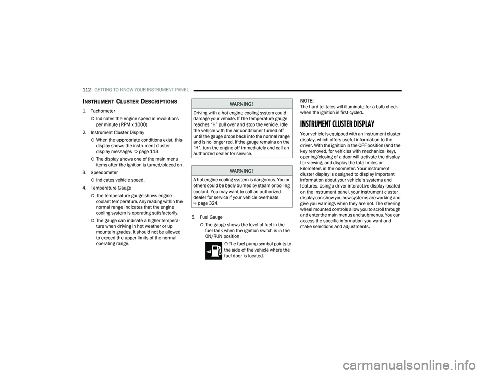
INSTRUMENT CLUSTER DESCRIPTIONS
1. Tachometer
Indicates the engine speed in revolutions
per minute (RPM x 1000).
2. Instrument Cluster Display
When the appropriate conditions exist, this
display shows the instrument cluster
display messages Ú page 113.
The display shows one of the main menu
items after the ignition is turned/placed on.
3. Speedometer
Indicates vehicle speed.
4. Temperature Gauge
The temperature gauge shows engine
coolant temperature. Any reading within the
normal range indicates that the engine
cooling system is operating satisfactorily.
The gauge can indicate a higher tempera -
ture when driving in hot weather or up
mountain grades. It should not be allowed
to exceed the upper limits of the normal
operating range. 5. Fuel GaugeThe gauge shows the level of fuel in the
fuel tank when the ignition switch is in the
ON/RUN position.
The fuel pump symbol points to
the side of the vehicle where the
fuel door is located.
NOTE:The hard telltales will illuminate for a bulb check
when the ignition is first cycled.
INSTRUMENT CLUSTER DISPLAY
Your vehicle is equipped with an instrument cluster
display, which offers useful information to the
driver. With the ignition in the OFF position (and the
key removed, for vehicles with mechanical key),
opening/closing of a door will activate the display
for viewing, and display the total miles or
kilometers in the odometer. Your instrument
cluster display is designed to display important
information about your vehicle’s systems and
features. Using a driver interactive display located
on the instrument panel, your instrument cluster
display can show you how systems are working and
give you warnings when they are not. The steering
wheel mounted controls allow you to scroll through
and enter the main menus and submenus. You can
access the specific information you want and
make selections and adjustments.
WARNING!
Driving with a hot engine cooling system could
damage your vehicle. If the temperature gauge
reaches “H” pull over and stop the vehicle. Idle
the vehicle with the air conditioner turned off
until the gauge drops back into the normal range
and is no longer red. If the gauge remains on the
“H”, turn the engine off immediately and call an
authorized dealer for service.
WARNING!
A hot engine cooling system is dangerous. You or
others could be badly burned by steam or boiling
coolant. You may want to call an authorized
dealer for service if your vehicle overheats
Ú page 324.
22_RUP_OM_EN_USC_t.book Page 112
Page 125 of 384
GETTING TO KNOW YOUR INSTRUMENT PANEL123
Electronic Throttle Control (ETC) Warning
Light
This warning light will illuminate to
indicate a problem with the ETC system.
If a problem is detected while the vehicle
is running, the light will either stay on or
flash depending on the nature of the problem.
Cycle the ignition when the vehicle is safely and
completely stopped and the transmission is placed
in the PARK (P) position. The light should turn off.
If the light remains on with the vehicle running,
your vehicle will usually be drivable; however, see
an authorized dealer for service as soon as
possible.
NOTE:This light may turn on if the accelerator and brake
pedals are pressed at the same time.
If the light continues to flash when the vehicle is
running, immediate service is required and you
may experience reduced performance, an
elevated/rough idle, or engine stall and your
vehicle may require towing. The light will come on
when the ignition is placed in the ON/RUN or ACC/
ON/RUN position and remain on briefly as a bulb
check. If the light does not come on during starting,
have the system checked by an authorized dealer.
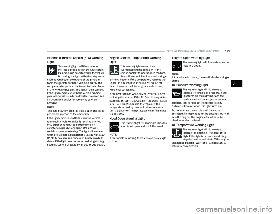
Engine Coolant Temperature Warning
Light
This warning light warns of an
overheated engine condition. If the
engine coolant temperature is too high,
this indicator will illuminate and a single
chime will sound. If the temperature reaches the
upper limit, a continuous chime will sound for
four minutes or until the engine is able to cool;
whichever comes first.
If the light turns on while driving, safely pull over
and stop the vehicle. If the Air Conditioning (A/C)
system is on, turn it off. Also, shift the transmission
into NEUTRAL (N) and idle the vehicle. If the
temperature reading does not return to normal,
turn the engine off immediately and call for service
Ú page 303.
Hood Open Warning Light
This warning light will illuminate when the
hood is left open and not fully closed.
NOTE:If the vehicle is moving, there will also be a single
chime.
Liftgate Open Warning Light
This warning light will illuminate when the
liftgate is open.
NOTE:If the vehicle is moving, there will also be a single
chime.
Oil Pressure Warning Light
This warning light will illuminate to
indicate low engine oil pressure. If the
light turns on while driving, stop the
vehicle, shut off the engine as soon as
possible, and contact an authorized dealer.
A chime will sound when this light turns on.
Do not operate the vehicle until the cause is
corrected. This light does not indicate how much oil
is in the engine. The engine oil level must be
checked under the hood.
Oil Temperature Warning Light
This warning light will illuminate to
indicate the engine oil temperature is
high. If the light turns on while driving,
stop the vehicle and shut off the engine
as soon as possible. Wait for oil temperature to
return to normal levels.
3
22_RUP_OM_EN_USC_t.book Page 123
Page 144 of 384
142STARTING AND OPERATING
DRIVE (D)
This range should be used for most city and
highway driving. It provides the smoothest upshifts
and downshifts, and the best fuel economy. The
transmission automatically upshifts through all
forward gears. The DRIVE position provides
optimum driving characteristics under all normal
operating conditions.
If the transmission temperature exceeds normal
operating limits, the transmission controller may
modify the transmission shift schedule, reduce
engine torque, and/or expand the range of torque
converter clutch engagement. This is done to
prevent transmission damage due to overheating.
If the transmission becomes extremely hot, the
Transmission Temperature Warning Light will
illuminate, a warning message will appear in the
instrument cluster, and the transmission may operate
differently until the transmission cools down.
During cold temperatures, transmission operation
may be modified depending on engine and
transmission temperature as well as vehicle
speed. This feature improves warm-up time of the
engine and transmission to achieve maximum
efficiency. Engagement of the torque converter
clutch, and shifts into EIGHTH or NINTH gear, are
inhibited until the transmission fluid is warm
Úpage 142. Normal operation will resume once
the transmission temperature has risen to a
suitable level.
LOW (L)
Use this range for engine braking when
descending very steep grades. In this range, the
transmission will downshift for increased engine
braking. To access the LOW position, push down
on the gear selector and rotate it fully clockwise.
Transmission Limp Home Mode
Transmission function is monitored electronically
for abnormal conditions. If a condition is detected
that could result in transmission damage,
Transmission Limp Home Mode is activated. In this
mode, the transmission may operate only in a fixed
gear, or may remain in NEUTRAL. The Malfunction
Indicator Light (MIL) may be illuminated. Limp
Home Mode may allow the vehicle to be driven to
an authorized dealer for service without damaging
the transmission.
In the event of a momentary problem, the
transmission can be reset to regain all forward
gears by performing the following steps:
1. Stop the vehicle.
2. Shift the transmission into PARK, if possible. If not, shift the transmission to NEUTRAL.
3. Push and hold the ignition switch until the engine turns off.
4. Wait approximately 30 seconds.
5. Restart the engine. 6. Shift into the desired gear range. If the
problem is no longer detected, the
transmission will return to normal operation.
NOTE:
Even if the transmission can be reset, we recommend
that you visit an authorized dealer at your earliest
possible convenience. An authorized dealer has diag -
nostic equipment to assess the condition of your
transmission. If the transmission cannot be reset,
authorized dealer service is required.
Torque Converter Clutch
A feature designed to improve fuel economy has been
included in the automatic transmission on your
vehicle. A clutch within the torque converter engages
automatically at calibrated speeds. This may result in
a slightly different feeling or response during normal
operation in the upper gears. When the vehicle speed
drops or during some accelerations, the clutch
automatically disengages.
NOTE:The torque converter clutch will not engage until
the engine and/or transmission is warm (usually
after 1 to 3 miles [2 to 5 km] of driving). Because
the engine speed is higher when the torque
converter clutch is not engaged, it may seem as if
the transmission is not shifting properly when the
vehicle is cold. This is normal. The torque converter
clutch will function normally once the powertrain is
sufficiently warm.
22_RUP_OM_EN_USC_t.book Page 142
Page 154 of 384
152STARTING AND OPERATING
When ACC Is Active
When you use the SET (-) button to decelerate, if
the engine’s braking power does not slow the
vehicle sufficiently to reach the set speed, the
brake system will automatically slow the
vehicle.
The ACC system decelerates the vehicle to a full
stop when following the vehicle in front. If your
vehicle follows the vehicle in front to a standstill,
after two seconds the driver will either have to
push the RES (resume) button, or apply the
accelerator pedal to reengage the ACC to the
existing set speed.
The ACC system maintains set speed when
driving uphill and downhill. However, a slight
speed change on moderate hills is normal. In
addition, downshifting may occur while climbing
uphill or descending downhill. This is normal
operation and necessary to maintain set speed.
When driving uphill and downhill, the ACC
system will cancel if the braking temperature
exceeds normal range (overheated).
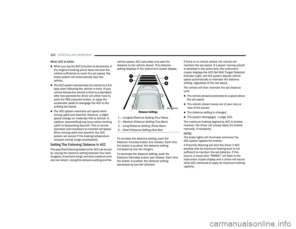
Setting The Following Distance In ACC
The specified following distance for ACC can be set
by varying the distance setting between four bars
(longest), three bars (long), two bars (medium) and
one bar (short). Using this distance setting and the vehicle speed, ACC calculates and sets the
distance to the vehicle ahead. This distance
setting displays in the instrument cluster display.
Distance Settings
To increase the distance setting, push the
Distance Increase button and release. Each time
the button is pushed, the distance setting
increases by one bar (longer).
To decrease the distance setting, push the
Distance Decrease button and release. Each time
the button is pushed, the distance setting
decreases by one bar (shorter). If there is no vehicle ahead, the vehicle will
maintain the set speed. If a slower moving vehicle
is detected in the same lane, the instrument
cluster displays the ACC Set With Target Detected
Indicator Light, and the system adjusts vehicle
speed automatically to maintain the distance
setting, regardless of the set speed.
The vehicle will then maintain the set distance
until:
The vehicle ahead accelerates to a speed above
the set speed.
The vehicle ahead moves out of your lane or
view of the sensor.
The distance setting is changed.
The system disengages Ú
page 150.
The maximum braking applied by ACC is limited;
however, the driver can always apply the brakes
manually, if necessary.
NOTE:The brake lights will illuminate whenever the
ACC system applies the brakes.
A Proximity Warning will alert the driver if ACC
predicts that its maximum braking level is not
sufficient to maintain the set distance. If this
occurs, a visual alert “BRAKE!” will flash in the
instrument cluster display and a chime will sound
while ACC continues to apply its maximum braking
capacity.
1 — Longest Distance Setting (Four Bars)
2 — Medium Distance Setting (Two Bars)
3 — Long Distance Setting (Three Bars)
4 — Short Distance Setting (One Bar)
22_RUP_OM_EN_USC_t.book Page 152
Page 305 of 384
IN CASE OF EMERGENCY303
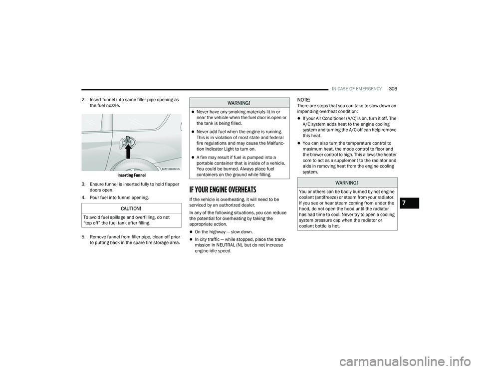
2. Insert funnel into same filler pipe opening as the fuel nozzle.
Inserting Funnel
3. Ensure funnel is inserted fully to hold flapper doors open.
4. Pour fuel into funnel opening.
5. Remove funnel from filler pipe, clean off prior to putting back in the spare tire storage area.
IF YOUR ENGINE OVERHEATS
If the vehicle is overheating, it will need to be
serviced by an authorized dealer.
In any of the following situations, you can reduce
the potential for overheating by taking the
appropriate action.
On the highway — slow down.
In city traffic — while stopped, place the trans -
mission in NEUTRAL (N), but do not increase
engine idle speed.
NOTE:There are steps that you can take to slow down an
impending overheat condition:
If your Air Conditioner (A/C) is on, turn it off. The
A/C system adds heat to the engine cooling
system and turning the A/C off can help remove
this heat.
You can also turn the temperature control to
maximum heat, the mode control to floor and
the blower control to high. This allows the heater
core to act as a supplement to the radiator and
aids in removing heat from the engine cooling
system.
CAUTION!
To avoid fuel spillage and overfilling, do not
“top off” the fuel tank after filling.
WARNING!
Never have any smoking materials lit in or
near the vehicle when the fuel door is open or
the tank is being filled.
Never add fuel when the engine is running.
This is in violation of most state and federal
fire regulations and may cause the Malfunc -
tion Indicator Light to turn on.
A fire may result if fuel is pumped into a
portable container that is inside of a vehicle.
You could be burned. Always place fuel
containers on the ground while filling.
WARNING!
You or others can be badly burned by hot engine
coolant (antifreeze) or steam from your radiator.
If you see or hear steam coming from under the
hood, do not open the hood until the radiator
has had time to cool. Never try to open a cooling
system pressure cap when the radiator or
coolant bottle is hot.
7
22_RUP_OM_EN_USC_t.book Page 303