service reset CHRYSLER PACIFICA HYBRID 2023 Owners Manual
[x] Cancel search | Manufacturer: CHRYSLER, Model Year: 2023, Model line: PACIFICA HYBRID, Model: CHRYSLER PACIFICA HYBRID 2023Pages: 328, PDF Size: 16.37 MB
Page 86 of 328
84GETTING TO KNOW YOUR VEHICLE
The key fob and the overhead console button will operate
the liftgate when the liftgate is locked. The outside handle
requires the liftgate to be unlocked. If the vehicle is
equipped with Passive Entry, pressing the touch pad on
the outside handle or Hands-Free Liftgate foot activation
(if equipped) will unlock and open the liftgate, with a valid
Passive Entry key fob within 5 ft (1.5 m) of the liftgate
handle.
NOTE:
To open the liftgate, the Hands-Free Liftgate foot acti -
vation (if equipped) requires a valid Passive Entry key
fob within 5 ft (1.5 m) of the door handle.
When you pull the electronic liftgate release handle,
either only the liftgate will unlock, or all the doors and
the liftgate will unlock, depending on the selected
setting in the Uconnect system.
Tones are sounded and the turn signals are flashed
with liftgate movements. These alerts can be turned on
or off in Uconnect Settings
Úpage 157. To Close The Liftgate
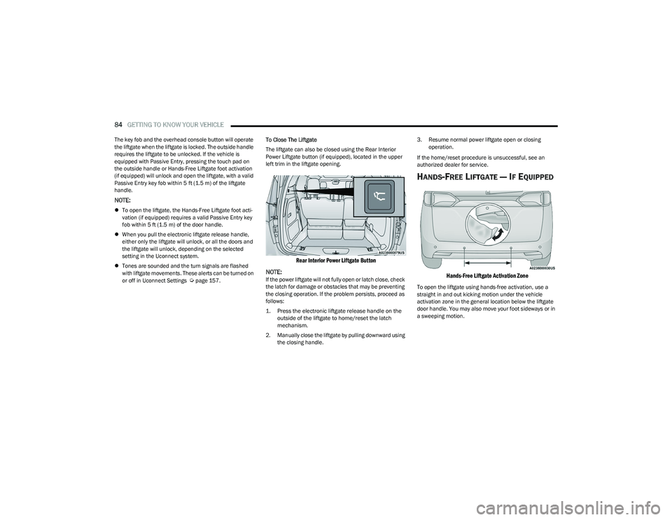
The liftgate can also be closed using the Rear Interior
Power Liftgate button (if equipped), located in the upper
left trim in the liftgate opening.
Rear Interior Power Liftgate Button
NOTE:
If the power liftgate will not fully open or latch close, check
the latch for damage or obstacles that may be preventing
the closing operation. If the problem persists, proceed as
follows:
1. Press the electronic liftgate release handle on the outside of the liftgate to home/reset the latch
mechanism.
2. Manually close the liftgate by pulling downward using the closing handle. 3. Resume normal power liftgate open or closing
operation.
If the home/reset procedure is unsuccessful, see an
authorized dealer for service.
HANDS-FREE LIFTGATE — IF EQUIPPED
Hands-Free Liftgate Activation Zone
To open the liftgate using hands-free activation, use a
straight in and out kicking motion under the vehicle
activation zone in the general location below the liftgate
door handle. You may also move your foot sideways or in
a sweeping motion.
23_RUP_OM_EN_USC_t.book Page 84
Page 87 of 328
GETTING TO KNOW YOUR VEHICLE85
Vehicles Equipped With A Trailer Tow Package
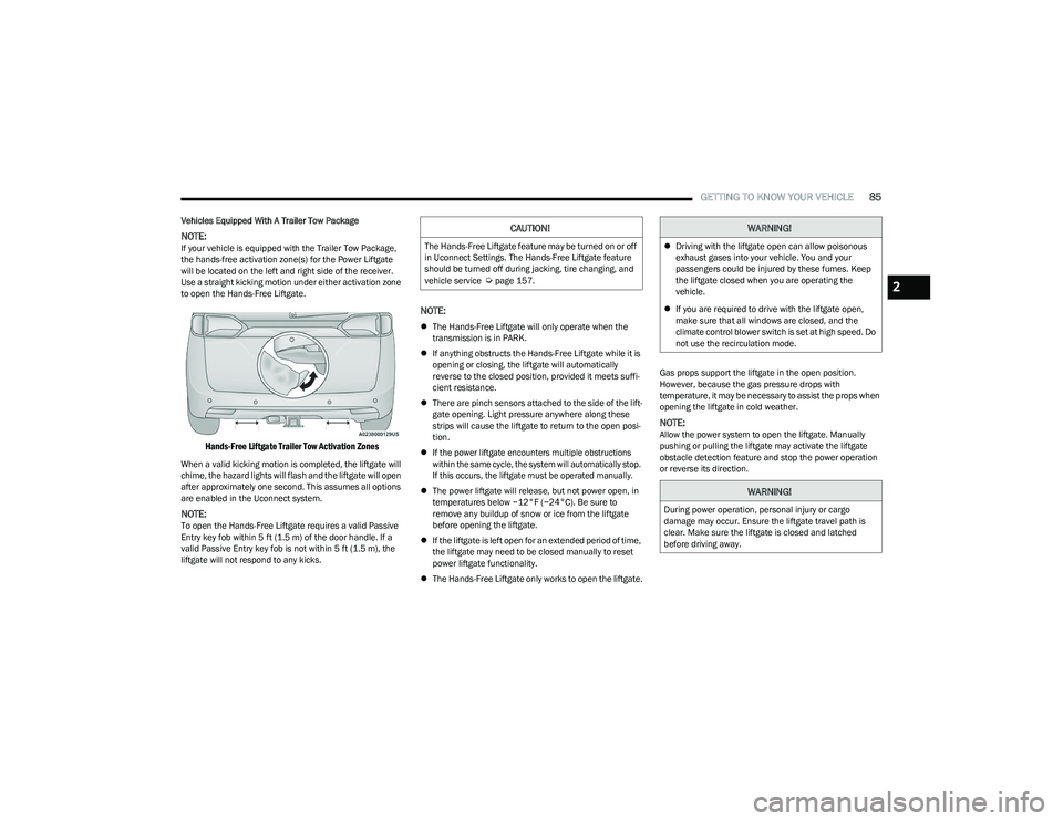
NOTE:If your vehicle is equipped with the Trailer Tow Package,
the hands-free activation zone(s) for the Power Liftgate
will be located on the left and right side of the receiver.
Use a straight kicking motion under either activation zone
to open the Hands-Free Liftgate.
Hands-Free Liftgate Trailer Tow Activation Zones
When a valid kicking motion is completed, the liftgate will
chime, the hazard lights will flash and the liftgate will open
after approximately one second. This assumes all options
are enabled in the Uconnect system.
NOTE:To open the Hands-Free Liftgate requires a valid Passive
Entry key fob within 5 ft (1.5 m) of the door handle. If a
valid Passive Entry key fob is not within 5 ft (1.5 m), the
liftgate will not respond to any kicks.
NOTE:
The Hands-Free Liftgate will only operate when the
transmission is in PARK.
If anything obstructs the Hands-Free Liftgate while it is
opening or closing, the liftgate will automatically
reverse to the closed position, provided it meets suffi -
cient resistance.
There are pinch sensors attached to the side of the lift -
gate opening. Light pressure anywhere along these
strips will cause the liftgate to return to the open posi -
tion.
If the power liftgate encounters multiple obstructions
within the same cycle, the system will automatically stop.
If this occurs, the liftgate must be operated manually.
The power liftgate will release, but not power open, in
temperatures below −12°F (−24°C). Be sure to
remove any buildup of snow or ice from the liftgate
before opening the liftgate.
If the liftgate is left open for an extended period of time,
the liftgate may need to be closed manually to reset
power liftgate functionality.
The Hands-Free Liftgate only works to open the liftgate. Gas props support the liftgate in the open position.
However, because the gas pressure drops with
temperature, it may be necessary to assist the props when
opening the liftgate in cold weather.
NOTE:Allow the power system to open the liftgate. Manually
pushing or pulling the liftgate may activate the liftgate
obstacle detection feature and stop the power operation
or reverse its direction.
CAUTION!
The Hands-Free Liftgate feature may be turned on or off
in Uconnect Settings. The Hands-Free Liftgate feature
should be turned off during jacking, tire changing, and
vehicle service
Úpage 157.
WARNING!
Driving with the liftgate open can allow poisonous
exhaust gases into your vehicle. You and your
passengers could be injured by these fumes. Keep
the liftgate closed when you are operating the
vehicle.
If you are required to drive with the liftgate open,
make sure that all windows are closed, and the
climate control blower switch is set at high speed. Do
not use the recirculation mode.
WARNING!
During power operation, personal injury or cargo
damage may occur. Ensure the liftgate travel path is
clear. Make sure the liftgate is closed and latched
before driving away.
2
23_RUP_OM_EN_USC_t.book Page 85
Page 101 of 328
GETTING TO KNOW YOUR INSTRUMENT PANEL99
INSTRUMENT CLUSTER DISPLAY MENU
I
TEMS
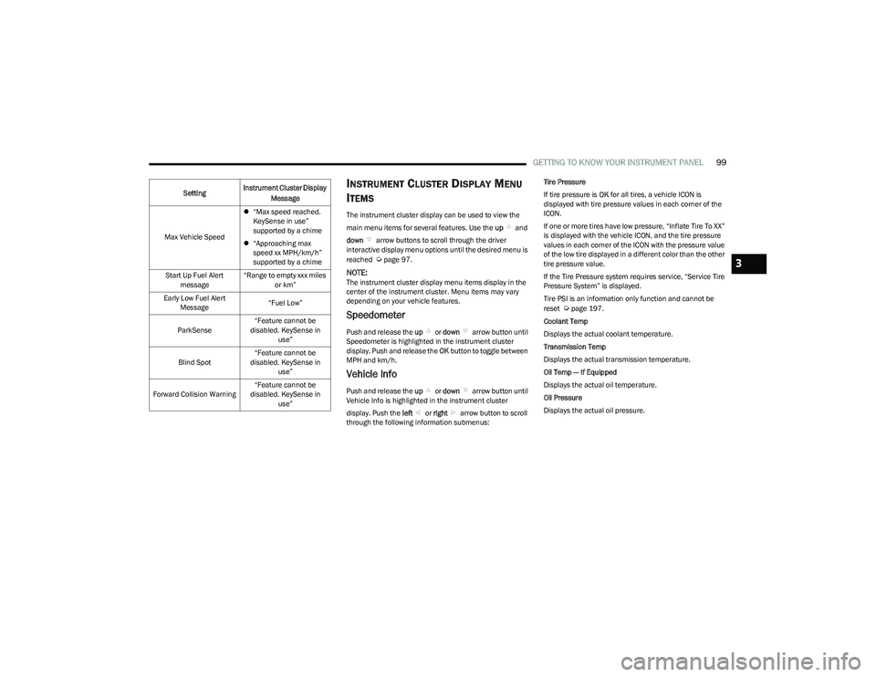
The instrument cluster display can be used to view the
main menu items for several features. Use the up and
down arrow buttons to scroll through the driver
interactive display menu options until the desired menu is
reached
Úpage 97.
NOTE:The instrument cluster display menu items display in the
center of the instrument cluster. Menu items may vary
depending on your vehicle features.
Speedometer
Push and release the up or down arrow button until
Speedometer is highlighted in the instrument cluster
display. Push and release the OK button to toggle between
MPH and km/h.
Vehicle Info
Push and release the up or down arrow button until
Vehicle Info is highlighted in the instrument cluster
display. Push the left or right arrow button to scroll
through the following information submenus: Tire Pressure
If tire pressure is
OK for all tires, a vehicle ICON is
displayed with tire pressure values in each corner of the
ICON.
If one or more tires have low pressure, “Inflate Tire To XX”
is displayed with the vehicle ICON, and the tire pressure
values in each corner of the ICON with the pressure value
of the low tire displayed in a different color than the other
tire pressure value.
If the Tire Pressure system requires service, “Service Tire
Pressure System” is displayed.
Tire PSI is an information only function and cannot be
reset
Úpage 197.
Coolant Temp
Displays the actual coolant temperature.
Transmission Temp
Displays the actual transmission temperature.
Oil Temp — If Equipped
Displays the actual oil temperature.
Oil Pressure
Displays the actual oil pressure.
Max Vehicle Speed
“Max speed reached.
KeySense in use”
supported by a chime
“Approaching max
speed xx MPH/km/h”
supported by a chime
Start Up Fuel Alert message “Range to empty xxx miles
or km”
Early Low Fuel Alert Message “Fuel Low”
ParkSense “Feature cannot be
disabled. KeySense in use”
Blind Spot “Feature cannot be
disabled. KeySense in use”
Forward Collision Warning “Feature cannot be
disabled. KeySense in use”
Setting
Instrument Cluster Display
Message
3
23_RUP_OM_EN_USC_t.book Page 99
Page 119 of 328
STARTING AND OPERATING117
(Continued)
(Continued)
Brake Service Mode
We recommend having your brakes serviced by an
authorized dealer. You should only make repairs for which
you have the knowledge and the right equipment. You
should only enter Brake Service Mode during brake
service.
When servicing your rear brakes, it may be necessary for
you or your technician to push the rear piston into the rear
caliper bore. With the Electric Park Brake (EPB) system,
this can only be done after retracting the EPB actuator.
Fortunately, actuator retraction can be done easily by
entering Brake Service in your vehicle
Úpage 158. This
menu-based system will guide you through the steps
necessary to retract the EPB actuator in order to perform
rear brake service.
Brake Service has requirements that must be met in order
to be activated:
The vehicle must be at a standstill.
The parking brake must be unapplied.
The transmission must be in PARK or NEUTRAL.
While in Brake Service, the EPB Warning Light will flash
continuously while the ignition switch is ON.
When brake service work is complete, the following steps
must be followed to reset the parking brake system to
normal operation:
Ensure the vehicle is at a standstill.
Press the brake pedal with moderate force.
Apply the EPB.
AUTOMATIC TRANSMISSION
You must press and hold the brake pedal while shifting out
of PARK.
WARNING!
You can be badly injured working on or around a motor
vehicle. Do only that service work for which you have
the knowledge and the right equipment. If you have any
doubt about your ability to perform a service job, take
your vehicle to a competent mechanic.
WARNING!
Never use the PARK position as a substitute for the
parking brake. Always apply the parking brake fully
when exiting the vehicle to guard against vehicle
movement and possible injury or damage.
Your vehicle could move and injure you and others if
it is not in PARK. Check by trying to move the trans -
mission gear selector out of PARK with the brake
pedal released. Make sure the transmission is in
PARK before exiting the vehicle.
The transmission may not engage PARK if the vehicle
is moving. Always bring the vehicle to a complete
stop before shifting to PARK, and verify that the
transmission gear position indicator solidly indicates
PARK (P) without blinking. Ensure that the vehicle is
completely stopped, and the PARK position is prop -
erly indicated, before exiting the vehicle.
It is dangerous to shift out of PARK or NEUTRAL if
the engine speed is higher than idle speed. If your
foot is not firmly pressing the brake pedal, the
vehicle could accelerate quickly forward or in
reverse. You could lose control of the vehicle and hit
someone or something. Only shift into gear when
the engine is idling normally and your foot is firmly
pressing the brake pedal.
Unintended movement of a vehicle could injure
those in or near the vehicle. As with all vehicles, you
should never exit a vehicle while the engine is
running. Before exiting a vehicle, always come to a
complete stop, then apply the parking brake, shift
the transmission into PARK, and turn the ignition
OFF. When the ignition is in the OFF position, the
transmission is locked in PARK, securing the vehicle
against unwanted movement.
When exiting the vehicle, always make sure the igni -
tion is in the OFF position, remove the key fob from
the vehicle, and lock the vehicle.
Never leave children alone in a vehicle, or with
access to an unlocked vehicle. Allowing children to
be in a vehicle unattended is dangerous for a
number of reasons. A child or others could be seri -
ously or fatally injured. Children should be warned
not to touch the parking brake, brake pedal or the
transmission gear selector.
WARNING!
4
23_RUP_OM_EN_USC_t.book Page 117
Page 122 of 328
120STARTING AND OPERATING
DRIVE (D)
This range should be used for most city and highway
driving. It provides the smoothest upshifts and downshifts,
and the best fuel economy. The transmission
automatically upshifts through all forward gears. The
DRIVE position provides optimum driving characteristics
under all normal operating conditions.
If the transmission temperature exceeds normal operating
limits, the transmission controller may modify the
transmission shift schedule, reduce engine torque, and/or
expand the range of torque converter clutch engagement.
This is done to prevent transmission damage due to
overheating.
If the transmission becomes extremely hot, the
Transmission Temperature Warning Light will illuminate, a
warning message will appear in the instrument cluster,
and the transmission may operate differently until the
transmission cools down.
During cold temperatures, transmission operation may be
modified depending on engine and transmission temperature
as well as vehicle speed. This feature improves warm-up time
of the engine and transmission to achieve maximum efficiency.
Engagement of the torque converter clutch, and shifts into
EIGHTH or NINTH gear, are inhibited until the transmission fluid
is warm
Ú
page 120. Normal operation will resume once the
transmission temperature has risen to a suitable level.
LOW (L)
Use this range for engine braking when descending very
steep grades. In this range, the transmission will
downshift for increased engine braking. To access the
LOW position, push down on the gear selector and rotate
it fully clockwise.
Transmission Limp Home Mode
Transmission function is monitored electronically for
abnormal conditions. If a condition is detected that could
result in transmission damage, Transmission Limp Home
Mode is activated. In this mode, the transmission may
operate only in a fixed gear, or may remain in NEUTRAL.
The Malfunction Indicator Light (MIL) may be illuminated.
Limp Home Mode may allow the vehicle to be driven to an
authorized dealer for service without damaging the
transmission.
In the event of a momentary problem, the transmission
can be reset to regain all forward gears by performing the
following steps:
1. Stop the vehicle.
2. Shift the transmission into PARK, if possible. If not, shift the transmission to NEUTRAL.
3. Push and hold the ignition switch until the engine turns off.
4. Wait approximately 30 seconds.
5. Restart the engine.
6. Shift into the desired gear range. If the problem is no longer detected, the transmission will return to
normal operation.
NOTE:Even if the transmission can be reset, we recommend that
you visit an authorized dealer at your earliest possible
convenience. An authorized dealer has diagnostic
equipment to assess the condition of your transmission. If
the transmission cannot be reset, authorized dealer
service is required.
Torque Converter Clutch
A feature designed to improve fuel economy has been
included in the automatic transmission on your vehicle. A
clutch within the torque converter engages automatically
at calibrated speeds. This may result in a slightly different
feeling or response during normal operation in the upper
gears. When the vehicle speed drops or during some
accelerations, the clutch automatically disengages.
NOTE:The torque converter clutch will not engage until the
engine and/or transmission is warm (usually after 1 to
3 miles [2 to 5 km] of driving). Because the engine speed
is higher when the torque converter clutch is not engaged,
it may seem as if the transmission is not shifting properly
when the vehicle is cold. This is normal. The torque
converter clutch will function normally once the powertrain
is sufficiently warm.
ALL-WHEEL DRIVE (AWD) — IF EQUIPPED
This feature provides on-demand All-Wheel Drive (AWD).
The system is automatic with no driver inputs or additional
driving skills required. Under normal driving conditions,
the front wheels provide most of the traction. If the front
wheels begin to lose traction, power is shifted
automatically to the rear wheels. The greater the front
wheel traction loss, the greater the power transfer to the
rear wheels.
Additionally, on dry pavement under heavy throttle input
(where one may have no wheel spin), torque will be sent to
the rear in a preemptive effort to improve vehicle launch
and performance characteristics.
23_RUP_OM_EN_USC_t.book Page 120
Page 125 of 328
STARTING AND OPERATING123
TO MANUALLY TURN ON THE STOP/
S
TART SYSTEM
After turning off the Stop/Start system, push the Stop/
Start OFF switch again (located on the switch bank). The
light on the switch will turn off.
SYSTEM MALFUNCTION
If there is a malfunction in the Stop/Start system, the
system will not shut down the engine. A “Service STOP/
START System” message and a yellow Stop/Start telltale
will appear in the instrument cluster display
If the “Service STOP/START System” message appears in
the instrument cluster display, have the system checked
by an authorized dealer.
If a malfunction occurs during an autostop, the vehicle
may not auto start and will need a key start.
CRUISE CONTROL SYSTEMS — IF EQUIPPED
Your vehicle may be equipped with the Cruise Control
system, or the Adaptive Cruise Control (ACC) system:
Cruise Control will keep your vehicle at a constant
preset speed.
Adaptive Cruise Control (ACC) will adjust the vehicle
speed up to the preset speed to maintain a distance
with the vehicle ahead.
NOTE:
In vehicles equipped with ACC, if ACC is not enabled,
Fixed Speed Cruise Control will not detect vehicles
directly ahead of you. Always be aware of the feature
selected.
Only one Cruise Control feature can operate at a time.
For example, if Fixed Speed Cruise Control is enabled,
Adaptive Cruise Control will be unavailable, and vice
versa.
CRUISE CONTROL
When engaged, the Cruise Control takes over accelerator
operations at speeds greater than 20 mph (32 km/h).
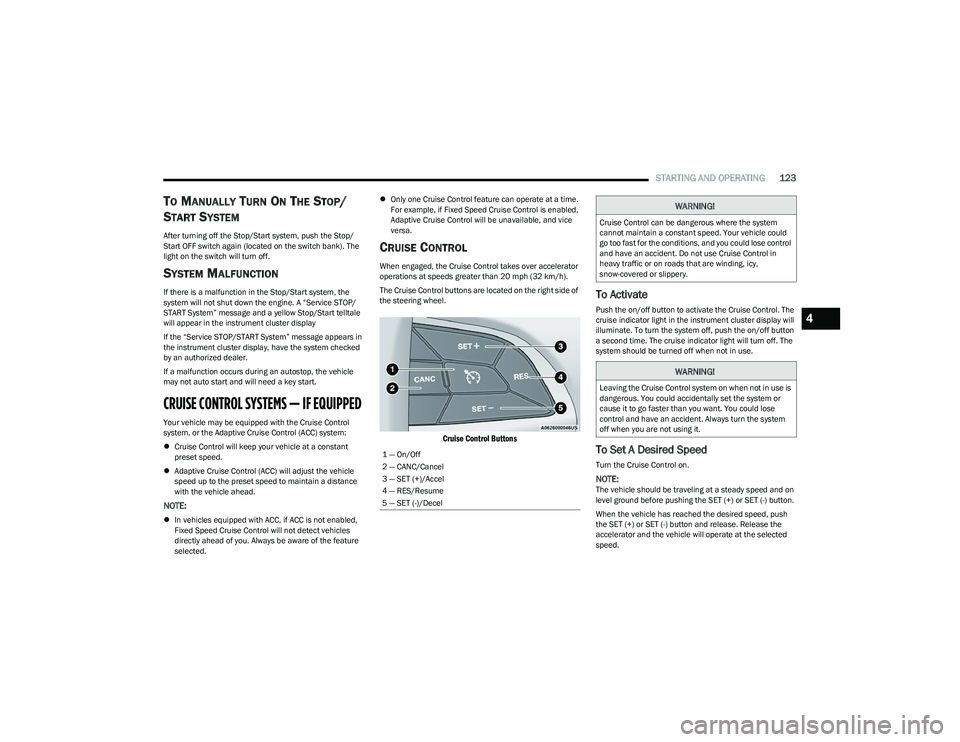
The Cruise Control buttons are located on the right side of
the steering wheel.
Cruise Control Buttons
To Activate
Push the on/off button to activate the Cruise Control. The
cruise indicator light in the instrument cluster display will
illuminate. To turn the system off, push the on/off button
a second time. The cruise indicator light will turn off. The
system should be turned off when not in use.
To Set A Desired Speed
Turn the Cruise Control on.
NOTE:The vehicle should be traveling at a steady speed and on
level ground before pushing the SET (+) or SET (-) button.
When the vehicle has reached the desired speed, push
the SET (+) or SET (-) button and release. Release the
accelerator and the vehicle will operate at the selected
speed.
1 — On/Off
2 — CANC/Cancel
3 — SET (+)/Accel
4 — RES/Resume
5 — SET (-)/Decel
WARNING!
Cruise Control can be dangerous where the system
cannot maintain a constant speed. Your vehicle could
go too fast for the conditions, and you could lose control
and have an accident. Do not use Cruise Control in
heavy traffic or on roads that are winding, icy,
snow-covered or slippery.
WARNING!
Leaving the Cruise Control system on when not in use is
dangerous. You could accidentally set the system or
cause it to go faster than you want. You could lose
control and have an accident. Always turn the system
off when you are not using it.
4
23_RUP_OM_EN_USC_t.book Page 123
Page 179 of 328
MULTIMEDIA177
REAR SEAT ENTERTAINMENT (RSE) WITH
AMAZON FIRE TV BUILT-IN — IF EQUIPPED
OVERVIEW
Rear Seat Entertainment with Fire TV built-in is designed
to give your family years of enjoyment.
Fire TV lets passengers enjoy a wide variety of content
from popular apps (subscriptions may be required).
Stream videos, play games, listen to music, get
information, and watch downloaded programs all while on
the road. Two Voice Remotes with Alexa are included with
the system. Press the Microphone button on the Voice
Remote with Alexa to easily find, launch, and control
content. Check sports scores, play music, control smart
home devices, or see your live camera feeds (compatible
smart home device required and sold separately). In
addition to streaming and downloaded content, changing
the input in Fire TV also enables you to:
Play your favorite CDs, DVDs, or Blu-ray™ Discs.
Mirror what’s on your phone or tablet to Fire TV via
Miracast capable devices.
Plug and play a variety of standard video games or
devices into the HDMI port.
Listen to audio over wired or wireless headphones (not
included, customer will have to provide their own or
play audio through in-cabin speakers with Listen In
feature in front seat).
Plug and play a variety of devices into the front seat
Video USB port. USB ports located under the rear
screens are charge only.
Watch content individually on each rear display or
mirror across both displays to watch together.
NOTE:Vehicle must be in an active and usable cellular range and
properly equipped with a Uconnect 5 NAV system and
Rear Seat Entertainment with Fire TV package. Streaming
requires a Wi-Fi connection and registered Amazon
account to run Fire TV in the vehicle. Streaming service
subscriptions are not included. Services and features are
subject to change or withdrawal at any time, may not be
available in all areas and languages, and may require
separate subscriptions.
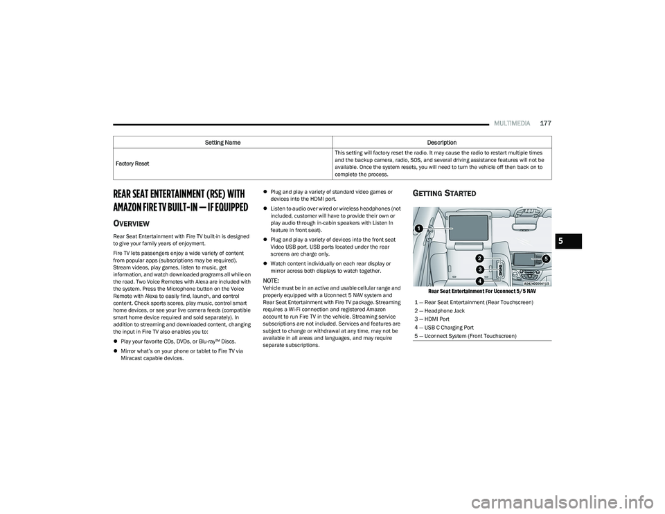
GETTING STARTED
Rear Seat Entertainment For Uconnect 5/5 NAV
Factory Reset This setting will factory reset the radio. It may cause the radio to restart multiple times
and the backup camera, radio, SOS, and several driving assistance features will not be
available. Once the system resets, you will need to turn the vehicle off then back on to
complete the process.
Setting Name
Description
1 — Rear Seat Entertainment (Rear Touchscreen)
2 — Headphone Jack
3 — HDMI Port
4 — USB C Charging Port
5 — Uconnect System (Front Touchscreen)
5
23_RUP_OM_EN_USC_t.book Page 177
Page 261 of 328
259
SERVICING AND MAINTENANCE
SCHEDULED SERVICING
Your vehicle is equipped with an automatic oil change
indicator system. The oil change indicator system will
remind you that it is time to take your vehicle in for
scheduled maintenance.
Based on engine operation conditions, the oil change
indicator message will illuminate. This means that service
is required for your vehicle. Operating conditions such as
frequent short-trips, trailer towing, extremely hot or cold
ambient temperatures will influence when the “Oil Change
Required” message is displayed. Have your vehicle
serviced as soon as possible, within the next 500 miles
(805 km).An authorized dealer will reset the oil change indicator
message after completing the scheduled oil change. If a
scheduled oil change is performed by someone other than
an authorized dealer Úpage 97.
NOTE:Under no circumstances should oil change intervals
exceed 10,000 miles (16,000 km), 12 months or
350 hours of engine run time, whichever comes first. The
350 hours of engine run or idle time is generally only a
concern for fleet customers.
Once A Month Or Before A Long Trip:
Check engine oil level.
Check windshield washer fluid level.
Check tire pressure and look for unusual wear or
damage. Rotate tires at the first sign of irregular wear,
even if it occurs before the oil indicator system turns
on.
Check the fluid levels of the coolant reservoir and
brake master cylinder, fill as needed.
Check function of all interior and exterior lights.
8
23_RUP_OM_EN_USC_t.book Page 259
Page 276 of 328
274SERVICING AND MAINTENANCE
(Continued)
Brake Master Cylinder
The fluid in the master cylinder should be checked when
performing under hood services or immediately if the
Brake Warning Light is illuminated.
Be sure to clean the top of the master cylinder area before
removing the cap. If necessary, add fluid to bring the fluid
level up to the requirements described on the brake fluid
reservoir. With disc brakes, fluid level can be expected to
fall as the brake pads wear. Brake fluid level should be
checked when pads are replaced. However, low fluid level
may be caused by a leak and a checkup may be needed.
Use only manufacturer recommended brake fluid
Úpage 307.AUTOMATIC TRANSMISSION
Special Additives
The manufacturer strongly recommends against using any
special additives in the transmission. Automatic
Transmission Fluid (ATF) is an engineered product and its
performance may be impaired by supplemental additives.
Therefore, do not add any fluid additives to the
transmission. Avoid using transmission sealers as they
may adversely affect seals.
Fluid Level Check
The fluid level is preset at the factory and does not require
adjustment under normal operating conditions. Routine
fluid level checks are not required; therefore the
transmission has no dipstick. An authorized dealer can
check your transmission fluid level using special service
tools. If you notice fluid leakage or transmission
malfunction, visit an authorized dealer immediately to
have the transmission fluid level checked. Operating the
vehicle with an improper fluid level can cause severe
transmission damage.
Fluid And Filter Changes
Under normal operating conditions, the fluid installed at
the factory will provide satisfactory lubrication for the life
of the vehicle.
Routine fluid and filter changes are not required. However,
change the fluid and filter if the fluid becomes
contaminated (with water, etc.), or if the transmission is
disassembled for any reason.
Selection Of Lubricant
It is important to use the proper transmission fluid to
ensure optimum transmission performance and life. Use
only the manufacturer specified transmission fluid
Úpage 307. It is important to maintain the transmission
fluid at the correct level using the recommended fluid.
WARNING!
Use only manufacturer recommended brake fluid Úpage 307. Using the wrong type of brake fluid can
severely damage your brake system and/or impair its
performance. The proper type of brake fluid for your
vehicle is also identified on the original factory
installed hydraulic master cylinder reservoir.
To avoid contamination from foreign matter or mois -
ture, use only new brake fluid or fluid that has been
in a tightly closed container. Keep the master
cylinder reservoir cap secured at all times. Brake
fluid in an open container absorbs moisture from the
air resulting in a lower boiling point. This may cause
it to boil unexpectedly during hard or prolonged
braking, resulting in sudden brake failure. This could
result in a collision.
Overfilling the brake fluid reservoir can result in
spilling brake fluid on hot engine parts, causing the
brake fluid to catch fire. Brake fluid can also damage
painted and vinyl surfaces, care should be taken to
avoid its contact with these surfaces.
Do not allow petroleum-based fluid to contaminate
the brake fluid. Brake seal components could be
damaged, causing partial or complete brake failure.
This could result in a collision.
CAUTION!
Do not use chemical flushes in your transmission as the
chemicals can damage your transmission components.
Such damage is not covered by the New Vehicle Limited
Warranty.
WARNING!
CAUTION!
If a transmission fluid leak occurs, visit an authorized
dealer immediately. Severe transmission damage may
occur. An authorized dealer has the proper tools to
adjust the fluid level accurately.
23_RUP_OM_EN_USC_t.book Page 274
Page 320 of 328
318
Load Shed Battery Saver On ....................................... 101
Load Shed Electrical Load Reduction......................... 101
Load Shed Intelligent Battery Sensor ......................... 101
Loading Vehicle ..................................................... 86
, 146
Tires ......................................................................... 288
Locks Automatic Door ..........................................................20
Child Protection .........................................................20
Manual ....................................................................... 20
Power Door .................................................................20
Low Tire Pressure System ........................................... 197
Lubrication, Body ......................................................... 268
Lug Nuts ....................................................................... 303
Luggage Carrier ............................................................... 90
MMaintenance ...................................................................81
Maintenance Free Battery ........................................... 263
Maintenance Schedule................................................ 259
Malfunction Indicator Light (Check Engine) ...... 106
, 110
Manual Park Release ........................................................... 254
Service ..................................................................... 311
Map/Reading Lights ....................................................... 58
Marker Lights, Side ...................................................... 282
Media Hub ....................................................................... 74 Memory Seat ...................................................................27
Methanol ...................................................................... 304 Mirrors ............................................................................. 48
Automatic Dimming................................................... 48
Exterior Folding.......................................................... 50
Heated................................................................. 48
, 50
Memory ...................................................................... 27
Outside ................................................................ 48
, 49
Rearview ...........................................................48, 236
Vanity.......................................................................... 48
Modifications/Alterations Vehicle.......................................................................... 8
Monitor, Tire Pressure System..................................... 197
Mopar Parts .................................................................. 311
MP3 Control .................................................................... 74 Multi-Function Control Lever .......................................... 54
NNew Vehicle Break-In Period ........................................ 114
OOccupant Restraints ..................................................... 200
Octane Rating, Gasoline (Fuel) .......................... 304, 306
Oil Change Indicator ....................................................... 98 Reset .......................................................................... 98
Oil Filter, Change .......................................................... 265
Oil Filter, Selection........................................................ 265
Oil Pressure Light.......................................................... 104 Oil, Engine ............................................................ 264
, 306
Capacity ................................................................... 306
Checking .................................................................. 263
Dipstick .................................................................... 263
Disposal ................................................................... 265
Filter ......................................................................... 265
Filter Disposal.......................................................... 265
Identification Logo .................................................. 264
Materials Added To ................................................. 265 Pressure Warning Light .......................................... 104Recommendation...........................................264
, 306
Synthetic .................................................................. 264
Viscosity ................................................................... 306
Onboard Diagnostic System ........................................ 109
Operating Precautions ................................................. 109
Operator Manual Owner's Manual ...................................................... 311
Outside Rearview Mirrors ....................................... 48
, 49
Overheating, Engine ..................................................... 253
PPaint Care ..................................................................... 300
Parking Brake ............................................................... 115
ParkSense Front And Rear ........................................................ 132
ParkSense Active Park Assist ...................................... 137
ParkSense System, Rear ............................................. 132
Passive Entry .................................................................. 21
Pets ............................................................................... 233
Placard, Tire And Loading Information ....................... 288
23_RUP_OM_EN_USC_t.book Page 318