engine CHRYSLER PT CRUISER 2009 1.G Owner's Manual
[x] Cancel search | Manufacturer: CHRYSLER, Model Year: 2009, Model line: PT CRUISER, Model: CHRYSLER PT CRUISER 2009 1.GPages: 410, PDF Size: 5.24 MB
Page 166 of 410
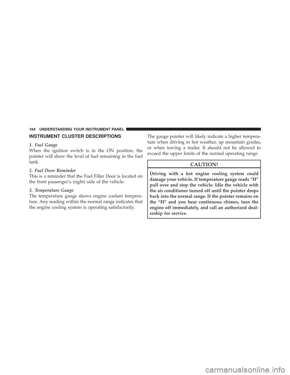
INSTRUMENT CLUSTER DESCRIPTIONS
1. Fuel Gauge
When the ignition switch is in the ON position, the
pointer will show the level of fuel remaining in the fuel
tank.
2. Fuel Door Reminder
This is a reminder that the Fuel Filler Door is located on
the front passenger’s (right) side of the vehicle.
3. Temperature Gauge
The temperature gauge shows engine coolant tempera-
ture. Any reading within the normal range indicates that
the engine cooling system is operating satisfactorily.The gauge pointer will likely indicate a higher tempera-
ture when driving in hot weather, up mountain grades,
or when towing a trailer. It should not be allowed to
exceed the upper limits of the normal operating range.
CAUTION!
Driving with a hot engine cooling system could
damage your vehicle. If temperature gauge reads “H”
pull over and stop the vehicle. Idle the vehicle with
the air conditioner turned off until the pointer drops
back into the normal range. If the pointer remains on
the “H” and you hear continuous chimes, turn the
engine off immediately, and call an authorized deal-
ership for service.
164 UNDERSTANDING YOUR INSTRUMENT PANEL
Page 167 of 410
WARNING!
A hot engine cooling system is dangerous. You or
others could be badly burned by steam or boiling
coolant. You may want to call an authorized dealer-
ship for service if your vehicle overheats. If you
decide to look under the hood yourself, see Section 7
of this manual. Follow the warnings under the Cool-
ing System Pressure Cap paragraph.
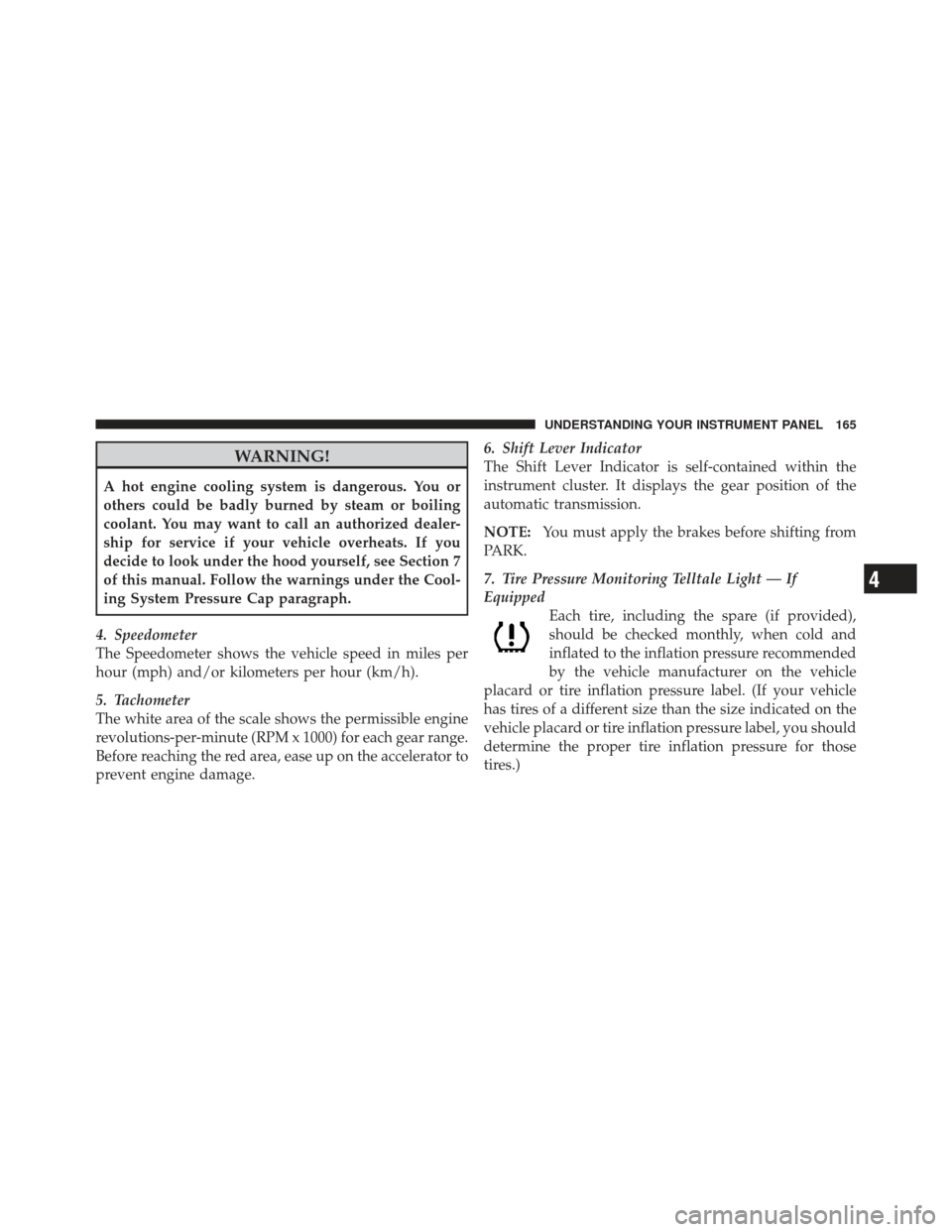
4. Speedometer
The Speedometer shows the vehicle speed in miles per
hour (mph) and/or kilometers per hour (km/h).
5. Tachometer
The white area of the scale shows the permissible engine
revolutions-per-minute (RPM x 1000) for each gear range.
Before reaching the red area, ease up on the accelerator to
prevent engine damage. 6. Shift Lever Indicator
The Shift Lever Indicator is self-contained within the
instrument cluster. It displays the gear position of the
automatic transmission.
NOTE:
You must apply the brakes before shifting from
PARK.
7. Tire Pressure Monitoring Telltale Light — If
Equipped Each tire, including the spare (if provided),
should be checked monthly, when cold and
inflated to the inflation pressure recommended
by the vehicle manufacturer on the vehicle
placard or tire inflation pressure label. (If your vehicle
has tires of a different size than the size indicated on the
vehicle placard or tire inflation pressure label, you should
determine the proper tire inflation pressure for those
tires.)
4
UNDERSTANDING YOUR INSTRUMENT PANEL 165
Page 170 of 410
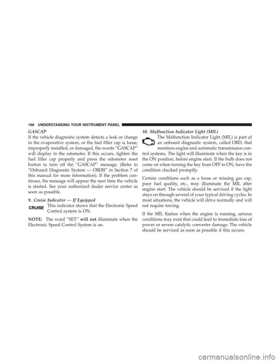
GASCAP
If the vehicle diagnostic system detects a leak or change
in the evaporative system, or the fuel filler cap is loose,
improperly installed, or damaged, the words “GASCAP”
will display in the odometer. If this occurs, tighten the
fuel filler cap properly and press the odometer reset
button to turn off the “GASCAP” message. (Refer to
“Onboard Diagnostic System — OBDII” in Section 7 of
this manual for more information). If the problem con-
tinues, the message will appear the next time the vehicle
is started. See your authorized dealer service center as
soon as possible.
9. Cruise Indicator — If EquippedThis indicator shows that the Electronic Speed
Control system is ON.
NOTE: The word “SET” will notilluminate when the
Electronic Speed Control System is on. 10. Malfunction Indicator Light (MIL)
The Malfunction Indicator Light (MIL) is part of
an onboard diagnostic system, called OBD, that
monitors engine and automatic transmission con-
trol systems. The light will illuminate when the key is in
the ON position, before engine start. If the bulb does not
come on when turning the key from OFF to ON, have the
condition checked promptly.
Certain conditions such as a loose or missing gas cap,
poor fuel quality, etc., may illuminate the MIL after
engine start. The vehicle should be serviced if the light
stays on through several of your typical driving cycles. In
most situations, the vehicle will drive normally and will
not require towing.
If the MIL flashes when the engine is running, serious
conditions may exist that could lead to immediate loss of
power or severe catalytic converter damage. The vehicle
should be serviced as soon as possible if this occurs.
168 UNDERSTANDING YOUR INSTRUMENT PANEL
Page 171 of 410
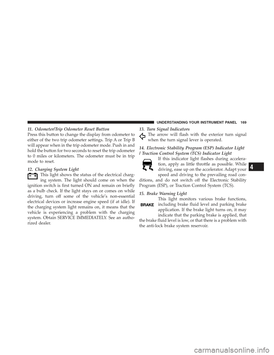
11. Odometer/Trip Odometer Reset Button
Press this button to change the display from odometer to
either of the two trip odometer settings. Trip A or Trip B
will appear when in the trip odometer mode. Push in and
hold the button for two seconds to reset the trip odometer
to 0 miles or kilometers. The odometer must be in trip
mode to reset.
12. Charging System LightThis light shows the status of the electrical charg-
ing system. The light should come on when the
ignition switch is first turned ON and remain on briefly
as a bulb check. If the light stays on or comes on while
driving, turn off some of the vehicle’s non-essential
electrical devices or increase engine speed (if at idle). If
the charging system light remains on, it means that the
vehicle is experiencing a problem with the charging
system. Obtain SERVICE IMMEDIATELY. See an autho-
rized dealer. 13. Turn Signal Indicators
The arrow will flash with the exterior turn signal
when the turn signal lever is operated.
14. Electronic Stability Program (ESP) Indicator Light
/ Traction Control System (TCS) Indicator Light If this indicator light flashes during accelera-
tion, apply as little throttle as possible. While
driving, ease up on the accelerator. Adapt your
speed and driving to the prevailing road con-
ditions, and do not switch off the Electronic Stability
Program (ESP), or Traction Control System (TCS).
15. Brake Warning Light This light monitors various brake functions,
including brake fluid level and parking brake
application. If the brake light turns on, it may
indicate that the parking brake is applied, that
the brake fluid level is low, or that there is a problem with
the anti-lock brake system reservoir.
4
UNDERSTANDING YOUR INSTRUMENT PANEL 169
Page 173 of 410
Operation of the Brake Warning Light can be checked by
turning the ignition switch from the OFF position to the
ON position. The light should illuminate for approxi-
mately two seconds. The light should then turn off unless
the parking brake is applied or a brake fault is detected.
If the light does not illuminate, have the light inspected
by an authorized dealer.
The light also will turn on when the parking brake is
applied with the ignition switch in the ON position.
NOTE:This light shows only that the parking brake is
applied. It does not show the degree of brake application.
16. Seat Belt Reminder Light When the ignition switch is first turned ON, this
light will turn on for five to eight seconds as a bulb
check. During the bulb check, if the driver’s seat
belt is unbuckled, a chime will sound. After the bulb
check or when driving, if the driver’s seat belt remains unbuckled, the Seat Belt Reminder Light will illuminate
and the chime will sound. Refer to “Occupant Restraints”
in Section 2 for more information.
17. Engine Temperature Warning Light
This light warns of an overheated engine condi-
tion. As temperatures rise and the gauge ap-
proaches H, this indicator will illuminate and a
single chime will sound after reaching a set threshold.
Further overheating will cause the temperature gauge to
pass H, the indicator will continuously flash and a
continuous chime will occur until the engine is allowed
to cool.
If the light turns on while driving, safely pull over and
stop the vehicle. If the A/C system is on, turn it off. Also,
shift the transmission into NEUTRAL and idle the ve-
hicle. If the temperature reading does not return to
4
UNDERSTANDING YOUR INSTRUMENT PANEL 171
Page 174 of 410

normal, turn the engine off immediately and call for
service. Refer to “If Your Engine Overheats” in Section 6
for more information.
18. Low Fuel LightWhen the fuel level reaches approximately 2.0 gal
(7.8 L) this light will turn on, and remain on until
fuel is added.
19. Vehicle Security Light — If Equipped This light will flash at a fast rate for approxi-
mately 15 seconds while the Vehicle Security
Alarm is arming, and then will flash slowly
until the vehicle is disarmed.
20. Front Fog Light Indicator — If Equipped This indicator will illuminate when the front fog
lights are on. 21. Anti-Lock Brake (ABS) Light
This light monitors the Anti-Lock Brake System
(ABS). The light will turn on when the ignition
switch is turned to the ON position and may
stay on for as long as four seconds.
If the ABS light remains on or turns on while driving, it
indicates that the Anti-Lock portion of the brake system
is not functioning and that service is required. However,
the conventional brake system will continue to operate
normally if the BRAKE warning light is not on.
If the ABS light is on, the brake system should be serviced
as soon as possible to restore the benefits of Anti-Lock
brakes. If the ABS light does not turn on when the
Ignition switch is turned to the ON position, have the
light inspected by an authorized dealer.
172 UNDERSTANDING YOUR INSTRUMENT PANEL
Page 175 of 410
22. Oil Pressure Warning LightThis light indicates low engine oil pressure. The
light should turn on momentarily when the engine
is started. If the light turns on while driving, stop the
vehicle and shut off the engine as soon as possible. A
chime will sound for four minutes when this light turns
on.
Do not operate the vehicle until the cause is corrected.
This light does not indicate how much oil is in the engine.
The engine oil level must be checked under the hood.
23. Airbag Warning Light This light turns on and remains on for seven
seconds as a bulb check when the ignition
switch is first turned ON. If the light is not on
during starting, stays on, or turns on while
driving, have the system inspected by an authorized
dealer as soon as possible. 24. High Beam Indicator
This indicator shows that the high beam head-
lights are on. Push the multifunction lever forward
to switch the headlights to high beam, and pull toward
yourself (normal position) to return to low beam.
25. Compass Mini-Trip Computer (CMTC) or Electronic
Vehicle Information Center (EVIC) Button—If Equipped
Pushing this button will switch between the different
EVIC functions.
Press the CMTC reset button to scroll through sub-menus
(i.e., Trip Functions: AVG Fuel Economy, DTE Elapsed
Time, and Units).
26. Compass Mini-Trip Computer (CMTC) or Electronic
Vehicle Information Center (EVIC) Display — If
Equipped
On vehicles equipped with Electronic Vehicle Informa-
tion Center (EVIC), when the appropriate conditions
4
UNDERSTANDING YOUR INSTRUMENT PANEL 173
Page 176 of 410

exist, this display shows the EVIC messages. Refer to
“Electronic Vehicle Information Center” in this section.
On vehicles equipped with Compass Mini-Trip Com-
puter (CMTC) the display provides the outside tempera-
ture, one of eight compass headings to indicate the
direction the vehicle is facing and the current radio
station. Refer to “Compass Mini-Trip Computer” in this
section.
COMPASS MINI-TRIP COMPUTER (CMTC) — IF
EQUIPPED
NOTE:The compass on your vehicle is self-calibrating,
eliminating the need to manually calibrate the compass.
The Compass Mini-Trip Computer features a driver-
interactive display (displays information on outside tem-
perature, compass direction, and trip information). The
display is located on the lower left part of the cluster
below the fuel and engine temperature gauge.
Compass Mini-Trip Computer Reset Button
CMTC Reset Button — Secondary Reset Button
Press the left Compass/Temperature RESET button to
scroll through sub-menus (i.e., Trip Functions: AVG Fuel
Economy, DTE Elapsed Time, and Units (US or Metric).
When the appropriate conditions exist, the following
messages will display in the window below the fuel and
engine temperature gauge:
E .................. Eight-point compass headings
are displayed (N, S, E, W, NE, NW, SE, SW)
14°F ............ T emperature (Fahrenheit or Celsius)
AV G .......... Average Fuel Economy (US or Metric)
DTE ....................... Distance to Empty
ET ............................ Elapsed Time
NOTE: Temperature and Average Fuel Economy can be
changed from U.S. or Metric. by pressing and holding the
(left) secondary pushbutton.
174 UNDERSTANDING YOUR INSTRUMENT PANEL
Page 177 of 410
Compass/Temperature Display
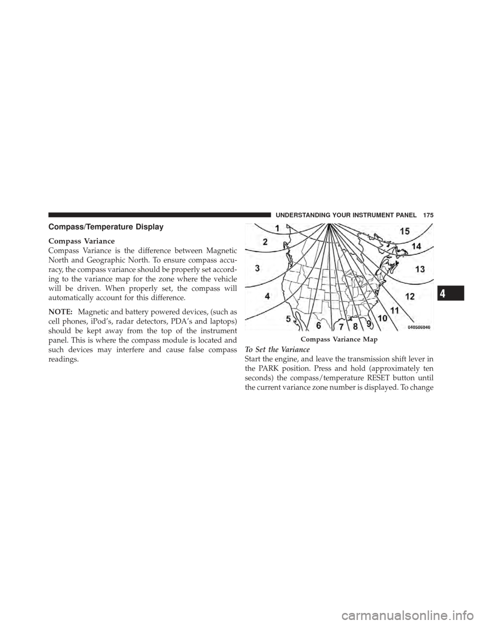
Compass Variance
Compass Variance is the difference between Magnetic
North and Geographic North. To ensure compass accu-
racy, the compass variance should be properly set accord-
ing to the variance map for the zone where the vehicle
will be driven. When properly set, the compass will
automatically account for this difference.
NOTE:Magnetic and battery powered devices, (such as
cell phones, iPod’s, radar detectors, PDA’s and laptops)
should be kept away from the top of the instrument
panel. This is where the compass module is located and
such devices may interfere and cause false compass
readings. To Set the Variance
Start the engine, and leave the transmission shift lever in
the PARK position. Press and hold (approximately ten
seconds) the compass/temperature RESET button until
the current variance zone number is displayed. To change
Compass Variance Map
4
UNDERSTANDING YOUR INSTRUMENT PANEL 175
Page 178 of 410
the zone, press and release the RESET button to incre-
ment the variance one step. Repeat as necessary, until the
desired variance is achieved.
NOTE:Zone 8 is the factory default. During program-
ming, the Zone Number will wrap around from Zone 15
to 1. Please refer to the Compass Variance Zone Map in
the following section: “Electronic Vehicle Information
Center (EVIC)”
Automatic Compass Calibration
The compass on your vehicle is self-calibrating, eliminat-
ing the need to manually calibrate the compass. When
the vehicle is new, the compass may appear erratic and
the CAL indicator message will flash in the CMTC until
the calibration is complete.
A good calibration requires a level surface and an envi-
ronment free from large metallic objects such as build-
ings, bridges, underground cables, railroad tracks, etc. Calibrate the compass by driving slowly, under 5 mph
(8 km/h) in one or more complete circles in a area free
from large metallic objects, until the CAL indicator in the
CMTC turns off. The compass will now function
normally.
Manual Compass Calibration
If the compass appears erratic or inaccurate, and the
variance has been properly set, you may wish to manu-
ally recalibrate the compass. To manually calibrate the
compass:
1. Start the engine, and leave the transmission shift lever
in the PARK position.
2. Press and hold (approximately 10 seconds) the
Compass/Temperature RESET button until the current
variance zone number is displayed.
176 UNDERSTANDING YOUR INSTRUMENT PANEL