battery location CHRYSLER TOWN AND COUNTRY 2002 User Guide
[x] Cancel search | Manufacturer: CHRYSLER, Model Year: 2002, Model line: TOWN AND COUNTRY, Model: CHRYSLER TOWN AND COUNTRY 2002Pages: 2399, PDF Size: 57.96 MB
Page 306 of 2399
(5) Continue filling coolant recovery pressure con-
tainer until level reaches the full line.
(6) Without installing the pressure/vent cap, start
and run engine at idle for a couple minutes.
(7) Recheck coolant level and fill as necessary.
(8) Install pressure/vent cap and drive vehicle for
approx. 10 km to reach normal operating tempera-
tures.
(9) Allow vehicle to cool. Check and fill coolant as
needed.
STANDARD PROCEDURE - COOLING SYSTEM
DRAINING
WARNING: DO NOT REMOVE OR LOOSEN THE
COOLANT PRESSURE/VENT CAP, CYLINDER
BLOCK DRAIN PLUGS, OR THE DRAINCOCK WHEN
THE SYSTEM IS HOT AND UNDER PRESSURE
BECAUSE SERIOUS BURNS FROM THE COOLANT
CAN OCCUR.(1)Without removing pressure/vent cap and
with system not under pressure, open the drain-
cock. The draincock is located on the lower right side
of radiator (Fig. 3).
(2) After the coolant recovery pressure container is
empty, then remove coolant pressure/vent cap.
COOLANT RECOVERY PRESS
CONTAINER
DESCRIPTION
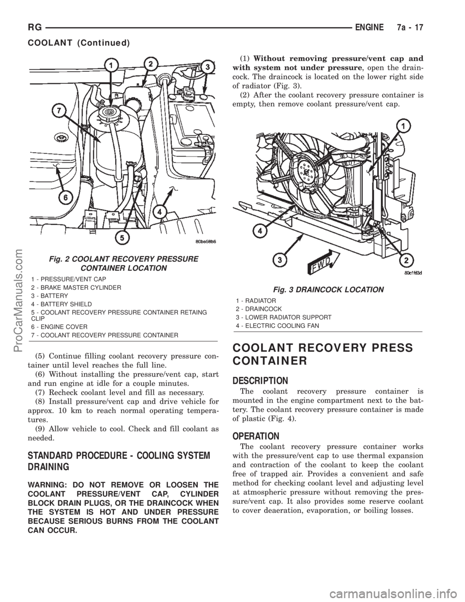
The coolant recovery pressure container is
mounted in the engine compartment next to the bat-
tery. The coolant recovery pressure container is made
of plastic (Fig. 4).
OPERATION
The coolant recovery pressure container works
with the pressure/vent cap to use thermal expansion
and contraction of the coolant to keep the coolant
free of trapped air. Provides a convenient and safe
method for checking coolant level and adjusting level
at atmospheric pressure without removing the pres-
sure/vent cap. It also provides some reserve coolant
to cover deaeration, evaporation, or boiling losses.
Fig. 2 COOLANT RECOVERY PRESSURE
CONTAINER LOCATION
1 - PRESSURE/VENT CAP
2 - BRAKE MASTER CYLINDER
3 - BATTERY
4 - BATTERY SHIELD
5 - COOLANT RECOVERY PRESSURE CONTAINER RETAING
CLIP
6 - ENGINE COVER
7 - COOLANT RECOVERY PRESSURE CONTAINER
Fig. 3 DRAINCOCK LOCATION
1 - RADIATOR
2 - DRAINCOCK
3 - LOWER RADIATOR SUPPORT
4 - ELECTRIC COOLING FAN
RGENGINE7a-17
COOLANT (Continued)
ProCarManuals.com
Page 307 of 2399
REMOVAL
(1) Drain cooling system below level of coolant
recovery pressure bottle. (Refer to 7 - COOLING/EN-
GINE/COOLANT - STANDARD PROCEDURE)
(2) Disconnect coolant bypass and overflow hoses
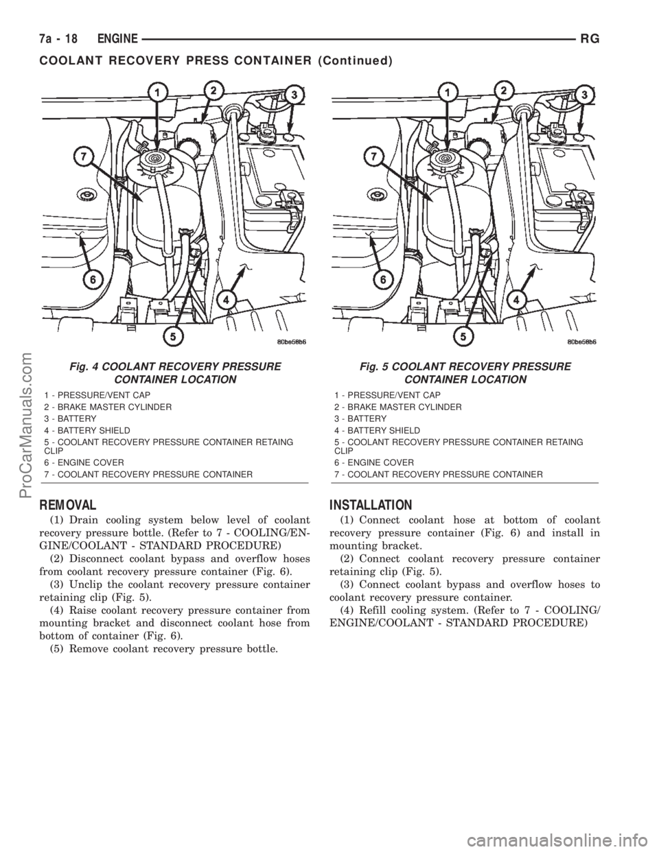
from coolant recovery pressure container (Fig. 6).
(3) Unclip the coolant recovery pressure container
retaining clip (Fig. 5).
(4) Raise coolant recovery pressure container from
mounting bracket and disconnect coolant hose from
bottom of container (Fig. 6).
(5) Remove coolant recovery pressure bottle.
INSTALLATION
(1) Connect coolant hose at bottom of coolant
recovery pressure container (Fig. 6) and install in
mounting bracket.
(2) Connect coolant recovery pressure container
retaining clip (Fig. 5).
(3) Connect coolant bypass and overflow hoses to
coolant recovery pressure container.
(4) Refill cooling system. (Refer to 7 - COOLING/
ENGINE/COOLANT - STANDARD PROCEDURE)
Fig. 4 COOLANT RECOVERY PRESSURE
CONTAINER LOCATION
1 - PRESSURE/VENT CAP
2 - BRAKE MASTER CYLINDER
3 - BATTERY
4 - BATTERY SHIELD
5 - COOLANT RECOVERY PRESSURE CONTAINER RETAING
CLIP
6 - ENGINE COVER
7 - COOLANT RECOVERY PRESSURE CONTAINER
Fig. 5 COOLANT RECOVERY PRESSURE
CONTAINER LOCATION
1 - PRESSURE/VENT CAP
2 - BRAKE MASTER CYLINDER
3 - BATTERY
4 - BATTERY SHIELD
5 - COOLANT RECOVERY PRESSURE CONTAINER RETAING
CLIP
6 - ENGINE COVER
7 - COOLANT RECOVERY PRESSURE CONTAINER
7a - 18 ENGINERG
COOLANT RECOVERY PRESS CONTAINER (Continued)
ProCarManuals.com
Page 308 of 2399

ENGINE COOLANT TEMP
SENSOR
DESCRIPTION
The engine coolant temperature sensor threads
into a coolant passage in the cylinder head (Fig. 7).
New sensors have sealant applied to the threads.
OPERATION
The coolant temperature (ECT) sensor is a nega-
tive temperature coefficient (NTC) thermistor (resis-
tance varies inversley with temperature). This means
at cold tempertures its resistance is high so the volt-
age signal will be high. As coolant temperture
increases, resistance decreases and the signal voltage
will be low. This allows the sensor to provide an ana-
log voltage signal to the ECM.
REMOVAL
WARNING: DO NOT REMOVE OR LOOSEN THE
COOLANT PRESSURE/VENT CAP, CYLINDER
BLOCK DRAIN PLUGS, OR THE DRAINCOCK WHEN
THE SYSTEM IS HOT AND UNDER PRESSURE
BECAUSE SERIOUS BURNS FROM THE COOLANT
CAN OCCUR.(1) Drain the cooling system. (Refer to 7 - COOL-
ING/ENGINE/COOLANT - STANDARD PROCE-
DURE)
(2) Disconnect coolant temperature sensor electri-
cal connector (Fig. 8).
(3) Remove coolant temperature sensor from cylin-
der head (Fig. 8).
INSTALLATION
(1) Install coolant temperature sensor in cylinder
head (Fig. 8).
(2) Connect coolant temperature sensor electrical
connector (Fig. 8).
(3) Refill the cooling system. (Refer to 7 - COOL-
ING/ENGINE/COOLANT - STANDARD PROCE-
DURE)
(4) Connect the negative battery cable.
Fig. 6 COOLANT RECOVERY PRESSURE
CONTAINER
1 - COOLANT RECOVERY PRESSURE CONTAINER
2 - COOLANT BYPASS HOSE
3 - OUTLET HOSE
4 - PRESSURE/VENT CAP
Fig. 7 COOLANT TEMPERATURE SENSOR
LOCATION
1 - EGR SOLENOID
2 - UPPER RADIATOR HOSE
3 - COOLANT TEMPERATURE SENSOR
4 - INTAKE MANIFOLD INLET
5 - INTAKE MANIFOLD/CYLINDER HEAD COVER
RGENGINE7a-19
COOLANT RECOVERY PRESS CONTAINER (Continued)
ProCarManuals.com
Page 309 of 2399

ENGINE COOLANT
THERMOSTAT
DESCRIPTION
A pellet-type thermostat controls the operating
temperature of the engine by controlling the amount
of coolant flow to the radiator (Fig. 9).
OPERATION
The thermostat starts to open at 80ÉC (176ÉF).
Above this temperature, coolant is allowed to flow to
the radiator. This provides quicker engine warmup
and overall temperature control.
The same thermostat is used for winter and sum-
mer seasons. An engine should not be operated with-
out a thermostat, except for servicing or testing.
Operating without a thermostat causes other prob-
lems. These are: longer engine warmup time, unreli-
able warmup performance, increased exhaust
emissions and crankcase condensation. This conden-
sation can result in sludge formation.
REMOVAL
NOTE: The thermostat is not serviced separately.
The thermostat and housing must be replaced as
an assembly.
(1) Disconnect negative battery cable.
(2) Drain cooling system (Refer to 7 - COOLING/
ENGINE/COOLANT - STANDARD PROCEDURE).
(3) Remove front wiper unit to gain access to ther-
mostat housing(Refer to 8 - ELECTRICAL/WIPERS/
WASHERS/WIPER MODULE - REMOVAL).
(4) Disconnect upper radiator hose adapter tube,
water pump hose, and EGR hose at thermostat hous-
ing.
(5) Remove both thermostat housing attaching
bolts and housing (Fig. 10).
INSTALLATION
(1) Install thermostat housing, gasket, and retain-
ing bolts (Fig. 10). Torque bolts to 27.5N´m.
(2) Connect upper radiator hose adapter tube,
water pump hose, and EGR cooler hose to thermostat
housing.
Fig. 8 COOLANT TEMPERATURE SENSOR
LOCATION
1 - EGR SOLENOID
2 - UPPER RADIATOR HOSE
3 - COOLANT TEMPERATURE SENSOR
4 - INTAKE MANIFOLD INLET
5 - INTAKE MANIFOLD/CYLINDER HEAD COVER
Fig. 9 THERMOSTAT HOUSING LOCATION
1 - CYLINDER HEAD COVER
2 - THERMOSTAT HOUSING
3 - AIR BLEED
4 - WATER PUMP
5 - WATER PUMP HOUSING TO THERMOSTAT HOUSING
BYPASS HOSE
6 - E G R VA LV E
7a - 20 ENGINERG
ENGINE COOLANT THERMOSTAT (Continued)
ProCarManuals.com
Page 312 of 2399
WATER PUMP
DESCRIPTION
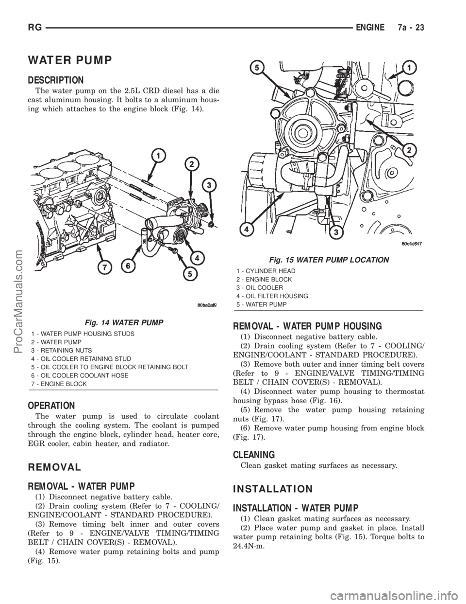
The water pump on the 2.5L CRD diesel has a die
cast aluminum housing. It bolts to a aluminum hous-
ing which attaches to the engine block (Fig. 14).
OPERATION
The water pump is used to circulate coolant
through the cooling system. The coolant is pumped
through the engine block, cylinder head, heater core,
EGR cooler, cabin heater, and radiator.
REMOVAL
REMOVAL - WATER PUMP
(1) Disconnect negative battery cable.
(2) Drain cooling system (Refer to 7 - COOLING/
ENGINE/COOLANT - STANDARD PROCEDURE).
(3) Remove timing belt inner and outer covers
(Refer to 9 - ENGINE/VALVE TIMING/TIMING
BELT / CHAIN COVER(S) - REMOVAL).
(4) Remove water pump retaining bolts and pump
(Fig. 15).
REMOVAL - WATER PUMP HOUSING
(1) Disconnect negative battery cable.
(2) Drain cooling system (Refer to 7 - COOLING/
ENGINE/COOLANT - STANDARD PROCEDURE).
(3) Remove both outer and inner timing belt covers
(Refer to 9 - ENGINE/VALVE TIMING/TIMING
BELT / CHAIN COVER(S) - REMOVAL).
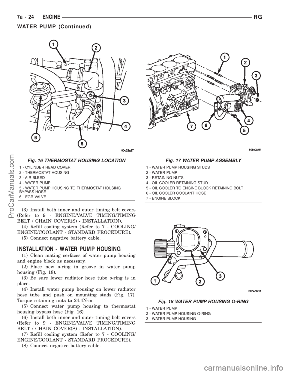
(4) Disconnect water pump housing to thermostat
housing bypass hose (Fig. 16).
(5) Remove the water pump housing retaining
nuts (Fig. 17).
(6) Remove water pump housing from engine block
(Fig. 17).
CLEANING
Clean gasket mating surfaces as necessary.
INSTALLATION
INSTALLATION - WATER PUMP
(1) Clean gasket mating surfaces as necessary.
(2) Place water pump and gasket in place. Install
water pump retaining bolts (Fig. 15). Torque bolts to
24.4N´m.
Fig. 14 WATER PUMP
1 - WATER PUMP HOUSING STUDS
2 - WATER PUMP
3 - RETAINING NUTS
4 - OIL COOLER RETAINING STUD
5 - OIL COOLER TO ENGINE BLOCK RETAINING BOLT
6 - OIL COOLER COOLANT HOSE
7 - ENGINE BLOCK
Fig. 15 WATER PUMP LOCATION
1 - CYLINDER HEAD
2 - ENGINE BLOCK
3 - OIL COOLER
4 - OIL FILTER HOUSING
5 - WATER PUMP
RGENGINE7a-23
ProCarManuals.com
Page 313 of 2399
(3) Install both inner and outer timing belt covers
(Refer to 9 - ENGINE/VALVE TIMING/TIMING
BELT / CHAIN COVER(S) - INSTALLATION).
(4) Refill cooling system (Refer to 7 - COOLING/
ENGINE/COOLANT - STANDARD PROCEDURE).
(5) Connect negative battery cable.
INSTALLATION - WATER PUMP HOUSING
(1) Clean mating serfaces of water pump housing
and engine block as necessary.
(2) Place new o-ring in groove in water pump
housing (Fig. 18).
(3) Be sure lower radiator hose tube o-ring is in
place.
(4) Install water pump housing on lower radiator
hose tube and push on mounting studs (Fig. 17).
Torque retaining nuts to 24.4N´m.
(5) Connect water pump housing to thermostat
housing bypass hose (Fig. 16).
(6) Install both inner and outer timing belt covers
(Refer to 9 - ENGINE/VALVE TIMING/TIMING
BELT / CHAIN COVER(S) - INSTALLATION).
(7) Refill cooling system (Refer to 7 - COOLING/
ENGINE/COOLANT - STANDARD PROCEDURE).
(8) Connect negative battery cable.
Fig. 16 THERMOSTAT HOUSING LOCATION
1 - CYLINDER HEAD COVER
2 - THERMOSTAT HOUSING
3 - AIR BLEED
4 - WATER PUMP
5 - WATER PUMP HOUSING TO THERMOSTAT HOUSING
BYPASS HOSE
6 - E G R VA LV E
Fig. 17 WATER PUMP ASSEMBLY
1 - WATER PUMP HOUSING STUDS
2 - WATER PUMP
3 - RETAINING NUTS
4 - OIL COOLER RETAINING STUD
5 - OIL COOLER TO ENGINE BLOCK RETAINING BOLT
6 - OIL COOLER COOLANT HOSE
7 - ENGINE BLOCK
Fig. 18 WATER PUMP HOUSING O-RING
1 - WATER PUMP
2 - WATER PUMP HOUSING O-RING
3 - WATER PUMP HOUSING
7a - 24 ENGINERG
WATER PUMP (Continued)
ProCarManuals.com
Page 318 of 2399
RADIATOR FAN RELAY
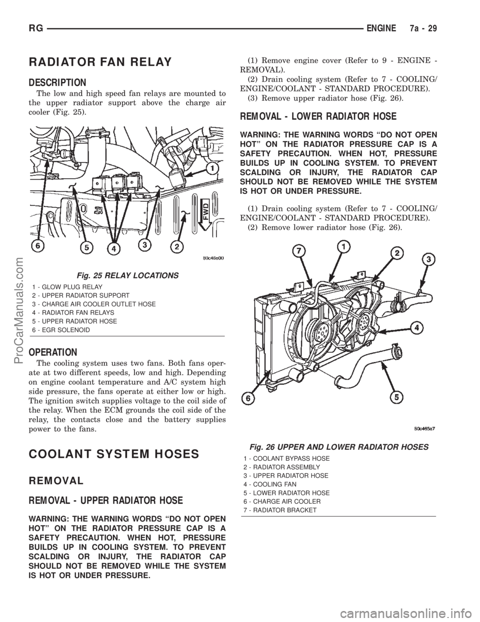
DESCRIPTION
The low and high speed fan relays are mounted to
the upper radiator support above the charge air
cooler (Fig. 25).
OPERATION
The cooling system uses two fans. Both fans oper-
ate at two different speeds, low and high. Depending
on engine coolant temperature and A/C system high
side pressure, the fans operate at either low or high.
The ignition switch supplies voltage to the coil side of
the relay. When the ECM grounds the coil side of the
relay, the contacts close and the battery supplies
power to the fans.
COOLANT SYSTEM HOSES
REMOVAL
REMOVAL - UPPER RADIATOR HOSE
WARNING: THE WARNING WORDS ªDO NOT OPEN
HOTº ON THE RADIATOR PRESSURE CAP IS A
SAFETY PRECAUTION. WHEN HOT, PRESSURE
BUILDS UP IN COOLING SYSTEM. TO PREVENT
SCALDING OR INJURY, THE RADIATOR CAP
SHOULD NOT BE REMOVED WHILE THE SYSTEM
IS HOT OR UNDER PRESSURE.(1) Remove engine cover (Refer to 9 - ENGINE -
REMOVAL).
(2) Drain cooling system (Refer to 7 - COOLING/
ENGINE/COOLANT - STANDARD PROCEDURE).
(3) Remove upper radiator hose (Fig. 26).
REMOVAL - LOWER RADIATOR HOSE
WARNING: THE WARNING WORDS ªDO NOT OPEN
HOTº ON THE RADIATOR PRESSURE CAP IS A
SAFETY PRECAUTION. WHEN HOT, PRESSURE
BUILDS UP IN COOLING SYSTEM. TO PREVENT
SCALDING OR INJURY, THE RADIATOR CAP
SHOULD NOT BE REMOVED WHILE THE SYSTEM
IS HOT OR UNDER PRESSURE.
(1) Drain cooling system (Refer to 7 - COOLING/
ENGINE/COOLANT - STANDARD PROCEDURE).
(2) Remove lower radiator hose (Fig. 26).
Fig. 25 RELAY LOCATIONS
1 - GLOW PLUG RELAY
2 - UPPER RADIATOR SUPPORT
3 - CHARGE AIR COOLER OUTLET HOSE
4 - RADIATOR FAN RELAYS
5 - UPPER RADIATOR HOSE
6 - EGR SOLENOID
Fig. 26 UPPER AND LOWER RADIATOR HOSES
1 - COOLANT BYPASS HOSE
2 - RADIATOR ASSEMBLY
3 - UPPER RADIATOR HOSE
4 - COOLING FAN
5 - LOWER RADIATOR HOSE
6 - CHARGE AIR COOLER
7 - RADIATOR BRACKET
RGENGINE7a-29
ProCarManuals.com
Page 321 of 2399
information and location views for the various wire
harness connectors, splices and grounds.
WARNING: ON VEHICLES EQUIPPED WITH AIR-
BAGS, REFER TO ELECTRICAL, RESTRAINTS
BEFORE ATTEMPTING ANY STEERING WHEEL,STEERING COLUMN, OR INSTRUMENT PANEL
COMPONENT DIAGNOSIS OR SERVICE. FAILURE
TO TAKE THE PROPER PRECAUTIONS COULD
RESULT IN ACCIDENTAL AIRBAG DEPLOYMENT
AND POSSIBLE PERSONAL INJURY.
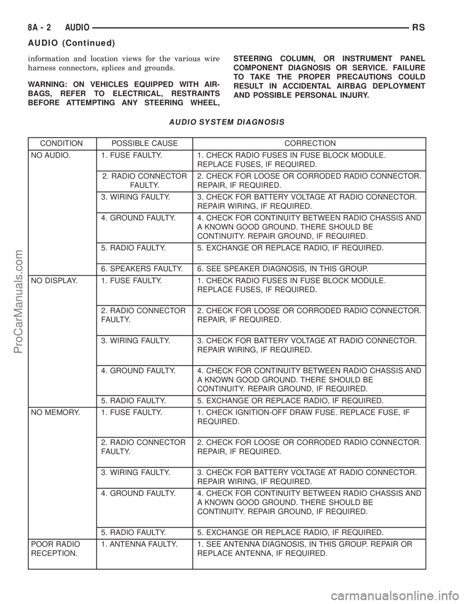
AUDIO SYSTEM DIAGNOSIS
CONDITION POSSIBLE CAUSE CORRECTION
NO AUDIO. 1. FUSE FAULTY. 1. CHECK RADIO FUSES IN FUSE BLOCK MODULE.
REPLACE FUSES, IF REQUIRED.
2. RADIO CONNECTOR
FAULTY.2. CHECK FOR LOOSE OR CORRODED RADIO CONNECTOR.
REPAIR, IF REQUIRED.
3. WIRING FAULTY. 3. CHECK FOR BATTERY VOLTAGE AT RADIO CONNECTOR.
REPAIR WIRING, IF REQUIRED.
4. GROUND FAULTY. 4. CHECK FOR CONTINUITY BETWEEN RADIO CHASSIS AND
A KNOWN GOOD GROUND. THERE SHOULD BE
CONTINUITY. REPAIR GROUND, IF REQUIRED.
5. RADIO FAULTY. 5. EXCHANGE OR REPLACE RADIO, IF REQUIRED.
6. SPEAKERS FAULTY. 6. SEE SPEAKER DIAGNOSIS, IN THIS GROUP.
NO DISPLAY. 1. FUSE FAULTY. 1. CHECK RADIO FUSES IN FUSE BLOCK MODULE.
REPLACE FUSES, IF REQUIRED.
2. RADIO CONNECTOR
FAULTY.2. CHECK FOR LOOSE OR CORRODED RADIO CONNECTOR.
REPAIR, IF REQUIRED.
3. WIRING FAULTY. 3. CHECK FOR BATTERY VOLTAGE AT RADIO CONNECTOR.
REPAIR WIRING, IF REQUIRED.
4. GROUND FAULTY. 4. CHECK FOR CONTINUITY BETWEEN RADIO CHASSIS AND
A KNOWN GOOD GROUND. THERE SHOULD BE
CONTINUITY. REPAIR GROUND, IF REQUIRED.
5. RADIO FAULTY. 5. EXCHANGE OR REPLACE RADIO, IF REQUIRED.
NO MEMORY. 1. FUSE FAULTY. 1. CHECK IGNITION-OFF DRAW FUSE. REPLACE FUSE, IF
REQUIRED.
2. RADIO CONNECTOR
FAULTY.2. CHECK FOR LOOSE OR CORRODED RADIO CONNECTOR.
REPAIR, IF REQUIRED.
3. WIRING FAULTY. 3. CHECK FOR BATTERY VOLTAGE AT RADIO CONNECTOR.
REPAIR WIRING, IF REQUIRED.
4. GROUND FAULTY. 4. CHECK FOR CONTINUITY BETWEEN RADIO CHASSIS AND
A KNOWN GOOD GROUND. THERE SHOULD BE
CONTINUITY. REPAIR GROUND, IF REQUIRED.
5. RADIO FAULTY. 5. EXCHANGE OR REPLACE RADIO, IF REQUIRED.
POOR RADIO
RECEPTION.1. ANTENNA FAULTY. 1. SEE ANTENNA DIAGNOSIS, IN THIS GROUP. REPAIR OR
REPLACE ANTENNA, IF REQUIRED.
8A - 2 AUDIORS
AUDIO (Continued)
ProCarManuals.com
Page 327 of 2399
NOTE: Use care when inserting CD changer so that
cable is not pinched or trapped against instrument
panel.
(3) Install screws holding CD changer.
(4) Reconnect the battery negative cable.
INSTRUMENT PANEL
ANTENNA CABLE
REMOVAL
WARNING: ON VEHICLES EQUIPPED WITH AIR-
BAGS, REFER TO ELECTRICAL, RESTRAINTS
BEFORE ATTEMPTING ANY STEERING WHEEL,
STEERING COLUMN, OR INSTRUMENT PANEL
COMPONENT DIAGNOSIS OR SERVICE. FAILURE
TO TAKE THE PROPER PRECAUTIONS COULD
RESULT IN ACCIDENTAL AIRBAG DEPLOYMENT
AND POSSIBLE PERSONAL INJURY.
(1) Disconnect and isolate the battery negative
cable.
(2) Remove glove box (Refer to 23 - BODY/IN-
STRUMENT PANEL/GLOVE BOX - REMOVAL).
(3) Disconnect extension cable end from antenna
cable end.
(4) Disconnect cable hanger clip from HVAC unit.
(5) Remove radio as necessary to gain access to
extension cable (Refer to 8 - ELECTRICAL/AUDIO/
RADIO - REMOVAL).
(6) Disconnect extension cable from back of radio.
(7) Remove extension cable from vehicle.
INSTALLATION
(1) Install extension cable to vehicle.
(2) Connect extension cable to back of radio.
(3) Install radio (Refer to 8 - ELECTRICAL/AU-
DIO/RADIO - INSTALLATION).
(4) Connect cable hanger clip to HVAC unit.
(5) Connect extension cable end to antenna cable
end.
(6) Install glove box (Refer to 23 - BODY/INSTRU-
MENT PANEL/GLOVE BOX - INSTALLATION).
(7) Connect the battery negative cable.
QUARTER GLASS INTEGRAL
ANTENNA - EXPORT
DESCRIPTION
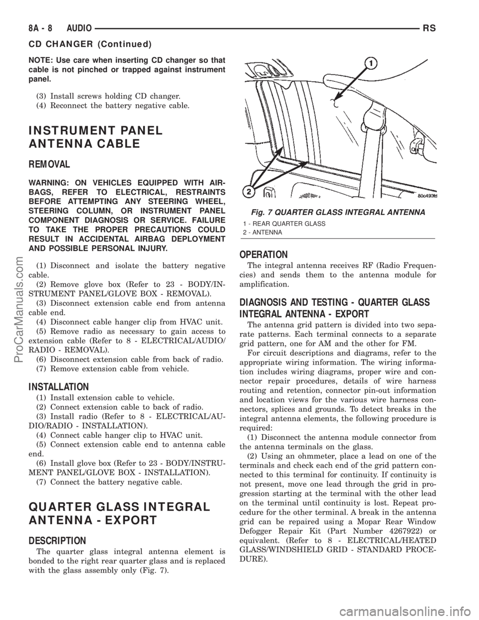
The quarter glass integral antenna element is
bonded to the right rear quarter glass and is replaced
with the glass assembly only (Fig. 7).
OPERATION
The integral antenna receives RF (Radio Frequen-
cies) and sends them to the antenna module for
amplification.
DIAGNOSIS AND TESTING - QUARTER GLASS
INTEGRAL ANTENNA - EXPORT
The antenna grid pattern is divided into two sepa-
rate patterns. Each terminal connects to a separate
grid pattern, one for AM and the other for FM.
For circuit descriptions and diagrams, refer to the
appropriate wiring information. The wiring informa-
tion includes wiring diagrams, proper wire and con-
nector repair procedures, details of wire harness
routing and retention, connector pin-out information
and location views for the various wire harness con-
nectors, splices and grounds. To detect breaks in the
integral antenna elements, the following procedure is
required:
(1) Disconnect the antenna module connector from
the antenna terminals on the glass.
(2) Using an ohmmeter, place a lead on one of the
terminals and check each end of the grid pattern con-
nected to this terminal for continuity. If continuity is
not present, move one lead through the grid in pro-
gression starting at the terminal with the other lead
on the terminal until continuity is lost. Repeat pro-
cedure for the other terminal. A break in the antenna
grid can be repaired using a Mopar Rear Window
Defogger Repair Kit (Part Number 4267922) or
equivalent. (Refer to 8 - ELECTRICAL/HEATED
GLASS/WINDSHIELD GRID - STANDARD PROCE-
DURE).
Fig. 7 QUARTER GLASS INTEGRAL ANTENNA
1 - REAR QUARTER GLASS
2 - ANTENNA
8A - 8 AUDIORS
CD CHANGER (Continued)
ProCarManuals.com
Page 328 of 2399
RADIO
DIAGNOSIS AND TESTING - RADIO
WARNING: ON VEHICLES EQUIPPED WITH AIR-
BAGS, REFER TO ELECTRICAL, RESTRAINTS
BEFORE ATTEMPTING ANY STEERING WHEEL,
STEERING COLUMN, OR INSTRUMENT PANEL
COMPONENT DIAGNOSIS OR SERVICE. FAILURE
TO TAKE THE PROPER PRECAUTIONS COULD
RESULT IN ACCIDENTAL AIRBAG DEPLOYMENT
AND POSSIBLE PERSONAL INJURY.
Any diagnosis of the Audio system should
begin with the use of the DRB IIItdiagnostic
tool. For information on the use of the DRB
IIIt, refer to the appropriate Diagnostic Service
Manual.
Refer to the appropriate wiring information. The
wiring information includes wiring diagrams, proper
wire and connector repair procedures, details of wire
harness routing and retention, connector pin-out
information and location views for the various wire
harness connectors, splices and grounds.
If the vehicle is equipped with remote radio
switches located on the back of the steering wheel
spokes, and the problem being diagnosed is related to
one of the symptoms listed below, be certain to check
the remote radio switches and circuits as described
in this group, prior to attempting radio diagnosis or
repair.
²Stations changing with no remote radio switch
input
²Radio memory presets not working properly
²Volume changes with no remote radio switch
input
²Remote radio switch buttons taking on other
functions
²CD player skipping tracks
²Remote radio switch inoperative.
CAUTION: The speaker output of the radio is a
ªfloating groundº system. Do not allow any speaker
lead to short to ground, as damage to the radio
may result.
(1) Check the fuse(s) in the junction block and the
Integrated Power Module (IPM). If OK, go to Step 2.
If not OK, repair the shorted circuit or component as
required and replace the faulty fuse(s).
(2) Check for battery voltage at the fuse in the
(IPM). If OK, go to Step 3. If not OK, repair the open
circuit to the battery as required.
(3) Turn the ignition switch to the ON position.
Check for battery voltage at the fuse in the junction
block. If OK, go to Step 4. If not OK, repair the open
circuit to the ignition switch as required.(4) Turn the ignition switch to the OFF position.
Remove the radio, but do not unplug the wire har-
ness connectors. Check for continuity between the
radio chassis and a good ground. There should be
continuity. If OK, go to Step 5. If not OK, repair the
open radio chassis ground circuit as required.
(5) Connect the battery negative cable. Turn the
ignition switch to the ON position. Check for battery
voltage at the fused ignition switch output circuit
cavity of the radio wire harness connector. If OK, go
to Step 6. If not OK, repair the open circuit as
required.
(6) Turn the ignition switch to the OFF position.
Check for battery voltage at the fused B(+) circuit
cavity of the radio wire harness connector. If OK,
replace the faulty radio. If not OK, repair the open
circuit to the Ignition-Off Draw (IOD) fuse as
required.
REMOVAL
(1) Disconnect and isolate the battery negative
cable.
(2) Remove cup holder.
(3) Remove trim panel above cupholder by pulling
straight out.
(4) Remove center instrument panel trim panel.
(5) Remove screws holding radio to instrument
panel.
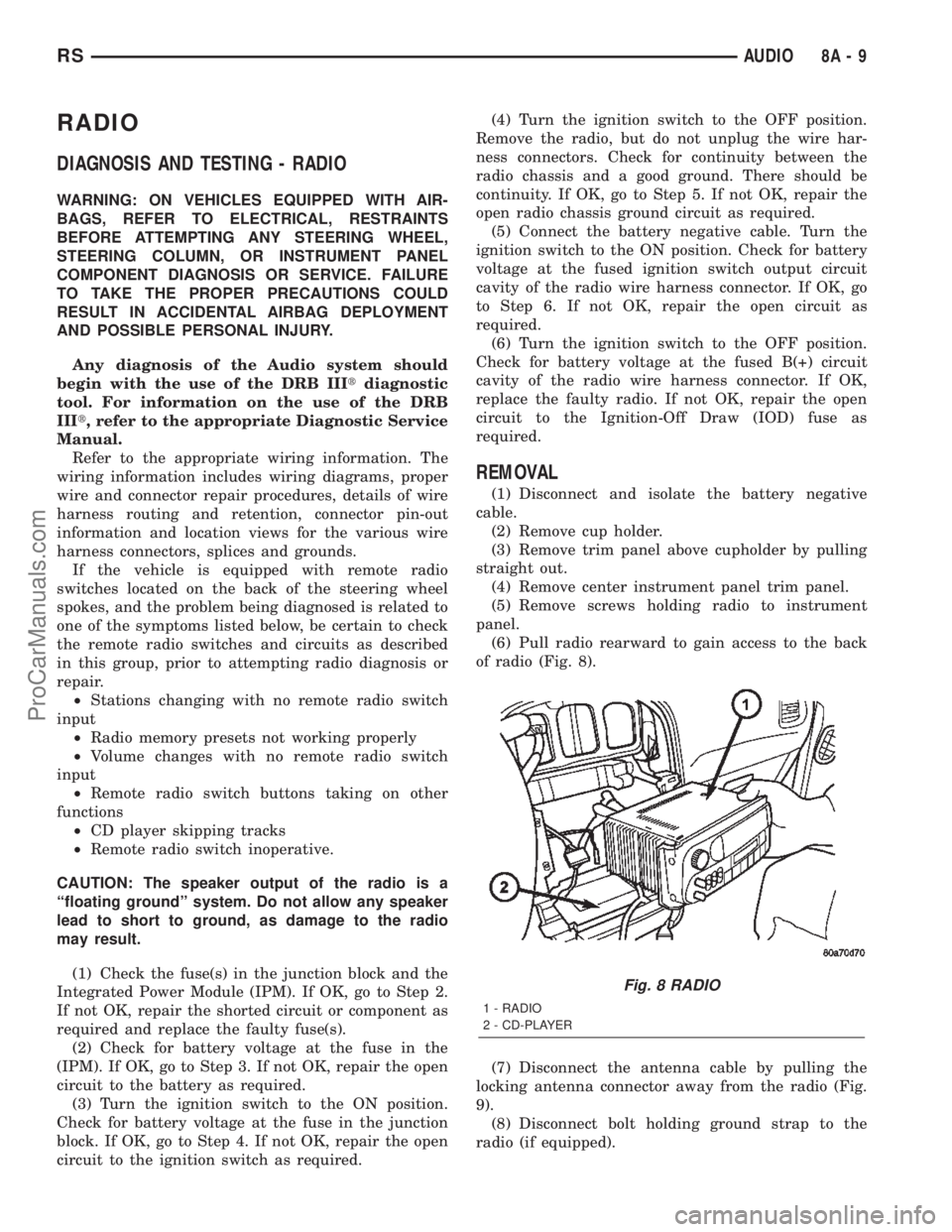
(6) Pull radio rearward to gain access to the back
of radio (Fig. 8).
(7) Disconnect the antenna cable by pulling the
locking antenna connector away from the radio (Fig.
9).
(8) Disconnect bolt holding ground strap to the
radio (if equipped).
Fig. 8 RADIO
1 - RADIO
2 - CD-PLAYER
RSAUDIO8A-9
ProCarManuals.com