index CHRYSLER TOWN AND COUNTRY 2002 User Guide
[x] Cancel search | Manufacturer: CHRYSLER, Model Year: 2002, Model line: TOWN AND COUNTRY, Model: CHRYSLER TOWN AND COUNTRY 2002Pages: 2399, PDF Size: 57.96 MB
Page 507 of 2399
INSTALLATION
CAUTION: Do not reuse the original brake lamp
switch. The switch can only be adjusted once. That
is during initial installation of the switch. If the
switch is not adjusted properly or has been
removed for some service, a new switch must be
installed and adjusted.
(1) Mount and adjust the NEW brake lamp switch
using the following procedure:
(a) Connect the wiring connector to the switch
and latch the locking tab.
(b) Install the switch in its bracket by aligning
the index tab on the switch with the slot in the
mounting bracket.
(c) When the switch is fully seated in its
bracket, rotate the switch clockwise approximately
30É to lock the switch into place (Fig. 3).
(d) With the brake pedal in the fully released
position, move the lever on the back of the brake
lamp switch from the angled non-adjusted position
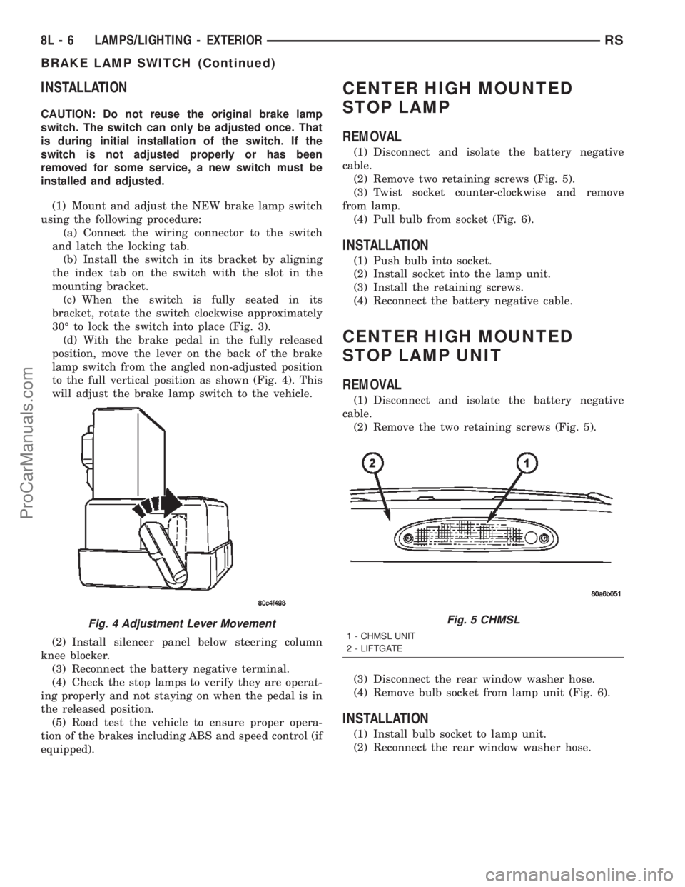
to the full vertical position as shown (Fig. 4). This
will adjust the brake lamp switch to the vehicle.
(2) Install silencer panel below steering column
knee blocker.
(3) Reconnect the battery negative terminal.
(4) Check the stop lamps to verify they are operat-
ing properly and not staying on when the pedal is in
the released position.
(5) Road test the vehicle to ensure proper opera-
tion of the brakes including ABS and speed control (if
equipped).
CENTER HIGH MOUNTED
STOP LAMP
REMOVAL
(1) Disconnect and isolate the battery negative
cable.
(2) Remove two retaining screws (Fig. 5).
(3) Twist socket counter-clockwise and remove
from lamp.
(4) Pull bulb from socket (Fig. 6).
INSTALLATION
(1) Push bulb into socket.
(2) Install socket into the lamp unit.
(3) Install the retaining screws.
(4) Reconnect the battery negative cable.
CENTER HIGH MOUNTED
STOP LAMP UNIT
REMOVAL
(1) Disconnect and isolate the battery negative
cable.
(2) Remove the two retaining screws (Fig. 5).
(3) Disconnect the rear window washer hose.
(4) Remove bulb socket from lamp unit (Fig. 6).
INSTALLATION
(1) Install bulb socket to lamp unit.
(2) Reconnect the rear window washer hose.
Fig. 4 Adjustment Lever MovementFig. 5 CHMSL
1 - CHMSL UNIT
2 - LIFTGATE
8L - 6 LAMPS/LIGHTING - EXTERIORRS
BRAKE LAMP SWITCH (Continued)
ProCarManuals.com
Page 658 of 2399
WIRING
TABLE OF CONTENTS
page page
WIRING DIAGRAM INFORMATION....... 8W-01-1
COMPONENT INDEX.................. 8W-02-1
POWER DISTRIBUTION............... 8W-10-1
GROUND DISTRIBUTION.............. 8W-15-1
BUS COMMUNICATIONS.............. 8W-18-1
CHARGING SYSTEM.................. 8W-20-1
STARTING SYSTEM.................. 8W-21-1
FUEL/IGNITION SYSTEM.............. 8W-30-1
TRANSMISSION CONTROL SYSTEM..... 8W-31-1
VEHICLE SPEED CONTROL............ 8W-33-1
ANTILOCK BRAKES................... 8W-35-1
VEHICLE THEFT SECURITY SYSTEM..... 8W-39-1
INSTRUMENT CLUSTER............... 8W-40-1
HORN/CIGAR LIGHTER/POWER OUTLET . . 8W-41-1
AIR CONDITIONING-HEATER........... 8W-42-1
AIRBAG SYSTEM.................... 8W-43-1
INTERIOR LIGHTING.................. 8W-44-1
BODY CONTROL MODULE............. 8W-45-1MESSAGE CENTER................... 8W-46-1
AUDIO SYSTEM..................... 8W-47-1
REAR WINDOW DEFOGGER............ 8W-48-1
OVERHEAD CONSOLE................. 8W-49-1
FRONT LIGHTING.................... 8W-50-1
REAR LIGHTING..................... 8W-51-1
TURN SIGNALS...................... 8W-52-1
WIPERS............................ 8W-53-1
TRAILER TOW....................... 8W-54-1
POWER WINDOWS................... 8W-60-1
POWER DOOR LOCKS................ 8W-61-1
POWER MIRRORS................... 8W-62-1
POWER SEATS...................... 8W-63-1
SPLICE INFORMATION................ 8W-70-1
CONNECTOR PIN-OUTS............... 8W-80-1
CONNECTOR/GROUND/SPLICE
LOCATION........................ 8W-91-1
POWER DISTRIBUTION SYSTEM........ 8W-97-1 RSWIRING
8W-1
ProCarManuals.com
Page 676 of 2399
8W-02 COMPONENT INDEX
Component Page
A/C Compressor Clutch Relay............ 8W-42
A/C Compressor Clutch................. 8W-42
A/C- Heater Control.................... 8W-42
A/C Pressure Sensor................... 8W-42
A/C-Heater Control.................... 8W-42
Accelerator Pedal Position Sensor......... 8W-30
Accessory Relay....................... 8W-10
Adjustable Pedals Module............... 8W-30
Adjustable Pedals Switch................ 8W-30
Airbag Control Module.................. 8W-43
Ambient Temp Sensor.................. 8W-49
Antenna............................. 8W-47
Auto Shut Down Relay................. 8W-30
Auto Temp Control..................... 8W-42
Automatic Day/Night Mirror............. 8W-49
Back-Up Lamp Switch.................. 8W-51
Battery Temperature Sensor............. 8W-20
Battery............................. 8W-20
Blend Door Actuators................... 8W-42
Body Control Module................... 8W-45
Boost Pressure Sensor.................. 8W-30
B-Pillar Switches...................... 8W-61
Brake Lamp Switch................. 8W-30, 51
Brake Transmission Shift Interlock
Solenoid........................... 8W-31
Cabin Heater Assist.................... 8W-30
Camshaft Position Sensor............... 8W-30
CD Changer.......................... 8W-47
Center High Mounted Stop Lamp......... 8W-51
Cinch/Release Motors................... 8W-61
Clockspring.................. 8W-33, 41, 43, 47
Clutch Pedal Interlock Switch Jumper..... 8W-10
Clutch Pedal Interlock Switch............ 8W-10
Combination Relays.................... 8W-54
Controller Antilock Brake............... 8W-35
Crank Case Ventilation Heater........... 8W-30
Crankshaft Position Sensor.............. 8W-30
Cylinder Lock Switches................. 8W-39
Data Link Connector................... 8W-18
Diagnostic Junction Port................ 8W-18
Door Ajar Switches.................... 8W-39
Door Lock Motor/Ajar Switches........... 8W-61
Door Lock Switches.................... 8W-61
Driver Airbag......................... 8W-43
EGR Solenoid......................... 8W-30
Electric Wiper De-Icer.................. 8W-48
Engine Control Module................. 8W-30
Engine Coolant Temp Sensor............. 8W-30
Engine Oil Pressure Switch.............. 8W-30
EVAP/Purge Solenoid................... 8W-30
Evaporator Temperature Sensor.......... 8W-42
Floor Console Lamp.................... 8W-44Component Page
Fog Lamps........................... 8W-50
Front Blower Module................... 8W-42
Front Blower Motor Relay............... 8W-42
Front Blower Motor.................... 8W-42
Front Cigar Lighter.................... 8W-41
Front Control Module.................. 8W-10
Front Fog Lamp Relay.................. 8W-50
Front Intrusion Sensor................. 8W-39
Front Washer Pump Motor.............. 8W-53
Front Wiper On/Off Relay............... 8W-53
Fuel Heater.......................... 8W-30
Fuel Injectors........................ 8W-30
Fuel Pressure Solenoid................. 8W-30
Fuel Pump Module.................... 8W-30
Full Open Switches.................... 8W-61
Fuselink............................. 8W-10
Fuses............................... 8W-10
Generator............................ 8W-20
Glow Plug Relay...................... 8W-30
Glow Plugs........................... 8W-30
Grounds............................. 8W-15
Halo Lamp........................... 8W-44
Headlamp Leveling Motors.............. 8W-50
Headlamp Switch...................... 8W-50
Headlamp Washer Relay................ 8W-53
Headlamps........................... 8W-50
Heated Seat Backs..................... 8W-63
Heated Seat Cushions.................. 8W-63
Heated Seat Modules................... 8W-63
High Beam Lamps..................... 8W-50
High Note Horn....................... 8W-41
Horn Relay.......................... 8W-41
Idle Air Control Motor.................. 8W-30
Ignition Coil.......................... 8W-30
Ignition Switch....................... 8W-10
Inlet Air Temperature Sensor............ 8W-30
Instrument Cluster.................... 8W-40
Instrument Panel Switch Bank . . 8W-44, 52, 53, 63
Integrated Power Module................ 8W-10
Knock Sensor......................... 8W-30
License Lamp......................... 8W-51
Lift Pump Motor...................... 8W-30
Liftgate Ajar Switch................. 8W-39, 61
Liftgate Cinch/Release Motor............. 8W-61
Liftgate Cylinder Lock Switch............ 8W-39
Liftgate Flood Lamps................... 8W-44
Liftgate Right Pinch Sensor.............. 8W-61
Low Beam Lamps.................... 8W-50-9
Manifold Absolute Pressure Sensor........ 8W-30
Mass Air Flow Sensor.................. 8W-30
Memory Seat/Mirror Module.......... 8W-62, 63
Memory Set Switch.................... 8W-63
RS8W-02 COMPONENT INDEX8W-02-1
ProCarManuals.com
Page 677 of 2399
Component Page
Mid Reading Lamps.................... 8W-44
Mode Door Actuator.................... 8W-42
Multi- Function Switch........... 8W-50, 52, 53
Output Speed Sensor................... 8W-31
Overhead Console..................... 8W-49
Oxygen Sensor 1/1 Upstream............. 8W-30
Oxygen Sensor 1/2 Downstream.......... 8W-30
Park Lamp Relay...................... 8W-10
Park Lamps.......................... 8W-50
Park/Turn Signal Lamps................ 8W-50
Parking Brake Switch.................. 8W-40
Passenger Airbag...................... 8W-43
Positive Temperature Coefficients......... 8W-10
Power Liftgate Module.................. 8W-61
Power Liftgate Motor................... 8W-61
Power Mirror Switch................... 8W-62
Power Mirrors........................ 8W-62
Power Outlet......................... 8W-41
Power Seat Circuit Breaker.............. 8W-10
Power Seat Front Riser Motors........... 8W-63
Power Seat Horizontal Motors............ 8W-63
Power Seat Horizontal Position Sensors.... 8W-63
Power Seat Rear Riser Motors............ 8W-63
Power Seat Rear Riser Position Sensors.... 8W-63
Power Seat Recliner Motors.............. 8W-63
Power Seat Switches................... 8W-63
Power Window Circuit Breaker........... 8W-10
Power Window Motors.................. 8W-60
Power Window Switches................ 8W-60
Powertrain Control Module.............. 8W-30
Radiator Fan Relays................... 8W-42
Radiator Fans........................ 8W-42
Radio Choke.......................... 8W-47
Radio............................... 8W-47
Reading Lamps....................... 8W-44
Rear A/C-Heater Unit.................. 8W-42
Rear Auto Temp Control Switch........... 8W-42
Rear Blower Front Control Switch......... 8W-42
Rear Blower Motor Power Module......... 8W-42
Rear Blower Motor Relay................ 8W-42
Rear Blower Motor..................... 8W-42
Rear Blower Rear Control Switch......... 8W-42
Rear Intrusion Sensor.................. 8W-39Component Page
Rear Lamp Assemblies.................. 8W-51
Rear Mode Motor...................... 8W-42
Rear Power Outlet..................... 8W-41
Rear Temperature Motor................ 8W-42
Rear Washer Pump Motor............... 8W-53
Rear Window Defogger Grid............. 8W-48
Recirculation Door Actuator.............. 8W-42
Remote Keyless Entry Antenna........... 8W-61
Remote Radio Switches................. 8W-47
Repeater Lamps....................... 8W-52
Seat Airbag.......................... 8W-43
Seat Belt Tensioners................... 8W-43
Sentry Key Immobilizer Module.......... 8W-39
Side Impact Airbag Control Modules....... 8W-43
Siren............................... 8W-39
Sliding Door Control Modules............ 8W-61
Sliding Door Latch Sensing Switches....... 8W-61
Sliding Door Lock Motor/Ajar Switches..... 8W-61
Sliding Door Lock Motors............... 8W-61
Sliding Door Motors.................... 8W-61
Solenoid/Pressure Switch Assy............ 8W-31
Speakers............................ 8W-47
Speed Control Servo................... 8W-33
Speed Control Switches................. 8W-33
Splice Information..................... 8W-70
Starter Motor Relay.................... 8W-21
Starter Motor......................... 8W-21
Stop/Turn Signal Relays................ 8W-54
Thatcham Alarm Module................ 8W-39
Throttle Position Sensor................ 8W-30
Torque Converter Clutch Solenoid......... 8W-31
Traction Control Switch................. 8W-35
Trailer Tow Connector.................. 8W-54
Transmission Control Module............ 8W-31
Transmission Range Sensor.............. 8W-31
Turn Signal Lamps.................... 8W-52
TXV Solenoid......................... 8W-42
Vehicle Speed Sensor................... 8W-30
Vent Motors.......................... 8W-60
Visor/Vanity Lamps.................... 8W-44
Washer Fluid Level Switch.............. 8W-53
Water In Fuel Sensor................... 8W-30
Wheel Speed Sensors................... 8W-35
8W - 02 - 2 8W-02 COMPONENT INDEXRS
ProCarManuals.com
Page 1148 of 2399

8W-91 CONNECTOR/GROUND/SPLICE LOCATION
TABLE OF CONTENTS
page
CONNECTOR/GROUND/SPLICE LOCATION
DESCRIPTION..........................1
CONNECTOR/GROUND/SPLICE
LOCATION
DESCRIPTION
This section provides illustrations identifying con-
nector, ground, and splice locations in the vehicle.Connector, ground, and splice indexes are provided.
Use the wiring diagrams in each section for connec-
tor, ground, and splice identification. Refer to the
appropriate index for the proper figure number. For
items that are not shown in this section N/S is placed
in the Fig. column.
CONNECTORS
CONNECTOR NAME/NUMBER COLOR LOCATION FIG.
A/C Compressor Clutch LTGY Top of A/C Compressor 9, 10, 11, 13, 14
A/C-Heater Control C1 (MTC) BK/RD Rear of Control 15, 18, 20
A/C-Heater Control C2 (MTC) BK/BL Rear of Control 15, 18, 20
A/C Pressure Transducer GY At Throttle Body 9, 11, 12, 13
Accelerator Pedal Position Sensor
(Diesel)BK At Accelerator Pedal 36
Airbag Control Module YL/RD Right Side of Instrument Panel 15, 19, 20
Ambient Temperature Sensor BK On Radiator Closure Panel 1
ATC Remote Sensor Above ATC Control N/S
Automatic Day/Night Mirror BK At Mirror N/S
Autostick Switch BK Rear of Switch 16, 17, 18
Auto Temperature Control C1
(ATC)WT Rear of Control N/S
Auto Temperature Control C2
(ATC)BK Rear of Control N/S
Auto Temperature Control C3
(ATC)Rear of Control N/S
Back-Up Lamp Switch BK On Transmission 12
Battery Temperature Sensor
(Diesel)BK At Battery N/S
Blower Motor Resistor C1 (MTC) BK Right Side of HVAC N/S
Blower Motor Resistor C2 (MTC) Right Side of HVAC N/S
Body Control Module C1 BK Under Left Instrument Panel 35, 36
Body Control Module C2 BK/GN Under Left Instrument Panel 35, 36
Body Control Module C3 BK/WT Under Left Instrument Panel 35, 36
Body Control Module C4 BK/GY Under Left Instrument Panel 15, 16, 25
Body Control Module C5 BK Under Left Instrument Panel 15, 16, 25
RS8W-91 CONNECTOR/GROUND/SPLICE LOCATION8W-91-1
ProCarManuals.com
Page 1201 of 2399
WARNING: ON VEHICLES EQUIPPED WITH AIR-
BAGS, REFER TO RESTRAINTS BEFORE ATTEMPT-
ING ANY STEERING WHEEL, STEERING COLUMN,
SEAT OR INSTRUMENT PANEL COMPONENT DIAG-
NOSIS OR SERVICE. FAILURE TO TAKE THE
PROPER PRECAUTIONS COULD RESULT IN ACCI-
DENTAL AIRBAG DEPLOYMENT AND POSSIBLE
PERSONAL INJURY.
(1) Check the fused B(+) fuse in the Integrated
Power Module (IPM). If OK, go to Step 2. If not OK,
repair the shorted circuit or component as required
and replace the faulty fuse.
(2) Check for battery voltage at the fused B(+) fuse
in the IPM. If OK, go to Step 3. If not OK, repair the
open fused B(+) circuit to the IPM fuse as required.
(3)
Open the power outlet door. Check for continuity
between the inside circumference of the power outlet
receptacle and a good ground. There should be continu-
ity. If OK, go to Step 4. If not OK, go to Step 5.
(4) Check for battery voltage at the insulated con-
tact located at the back of the power outlet recepta-
cle. If not OK, go to Step 5.
(5) Disconnect and isolate the battery negative
cable. Remove the appropriate bezel. Check for conti-
nuity between the ground circuit cavity of the power
outlet wire harness connector and a good ground.
There should be continuity. If OK, go to Step 6. If not
OK, repair the open ground circuit to ground as
required.
(6) Connect the battery negative cable. Check for
battery voltage at the fused B(+) circuit cavity of the
power outlet wire harness connector. If OK, replace
the faulty power outlet receptacle. If not OK, repair
the open fused B(+) circuit to the IPM fuse as
required.
REMOVAL
(1) Disconnect and isolate the battery negative
cable.
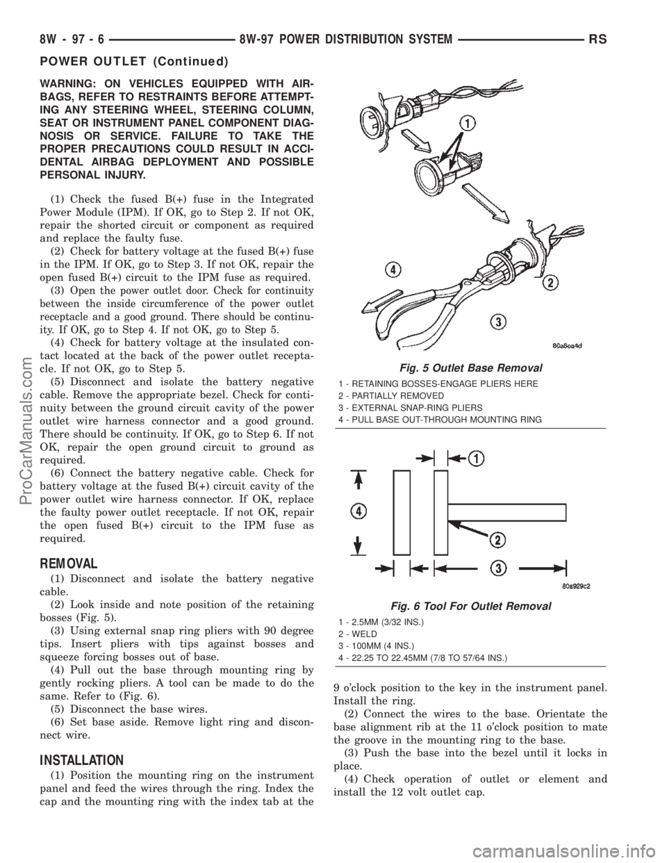
(2) Look inside and note position of the retaining
bosses (Fig. 5).
(3) Using external snap ring pliers with 90 degree
tips. Insert pliers with tips against bosses and
squeeze forcing bosses out of base.
(4) Pull out the base through mounting ring by
gently rocking pliers. A tool can be made to do the
same. Refer to (Fig. 6).
(5) Disconnect the base wires.
(6) Set base aside. Remove light ring and discon-
nect wire.
INSTALLATION
(1) Position the mounting ring on the instrument
panel and feed the wires through the ring. Index the
cap and the mounting ring with the index tab at the9 o'clock position to the key in the instrument panel.
Install the ring.
(2) Connect the wires to the base. Orientate the
base alignment rib at the 11 o'clock position to mate
the groove in the mounting ring to the base.
(3) Push the base into the bezel until it locks in
place.
(4) Check operation of outlet or element and
install the 12 volt outlet cap.
Fig. 5 Outlet Base Removal
1 - RETAINING BOSSES-ENGAGE PLIERS HERE
2 - PARTIALLY REMOVED
3 - EXTERNAL SNAP-RING PLIERS
4 - PULL BASE OUT-THROUGH MOUNTING RING
Fig. 6 Tool For Outlet Removal
1 - 2.5MM (3/32 INS.)
2 - WELD
3 - 100MM (4 INS.)
4 - 22.25 TO 22.45MM (7/8 TO 57/64 INS.)
8W - 97 - 6 8W-97 POWER DISTRIBUTION SYSTEMRS
POWER OUTLET (Continued)
ProCarManuals.com
Page 1443 of 2399
(3) Install the six nuts attaching rear bumper rein-
forcement to frame rail extensions and tighten to 27
N´m (20 ft. lbs.) torque (Fig. 4).
(4) Install rear bumper fascia. (Refer to 13 -
FRAMES & BUMPERS/BUMPERS/REAR FASCIA -
INSTALLATION).
REAR FASCIA - SCUFF PAD
REMOVAL
The scuff pad may not be salvageable during the
removal process. The scuff pad should be replaced if
damaged or broken. Check availability before servic-
ing. The scuff pad serviceability is improved if the
rear fascia is to be removed for service.
NOTE: If the rear fascia is to be removed for other
service issues or If the scuff pad is to be reused
use the steps below.
(1) Remove rear bumper fascia.(Refer to 13 -
FRAMES & BUMPERS/BUMPERS/REAR FASCIA -
REMOVAL)
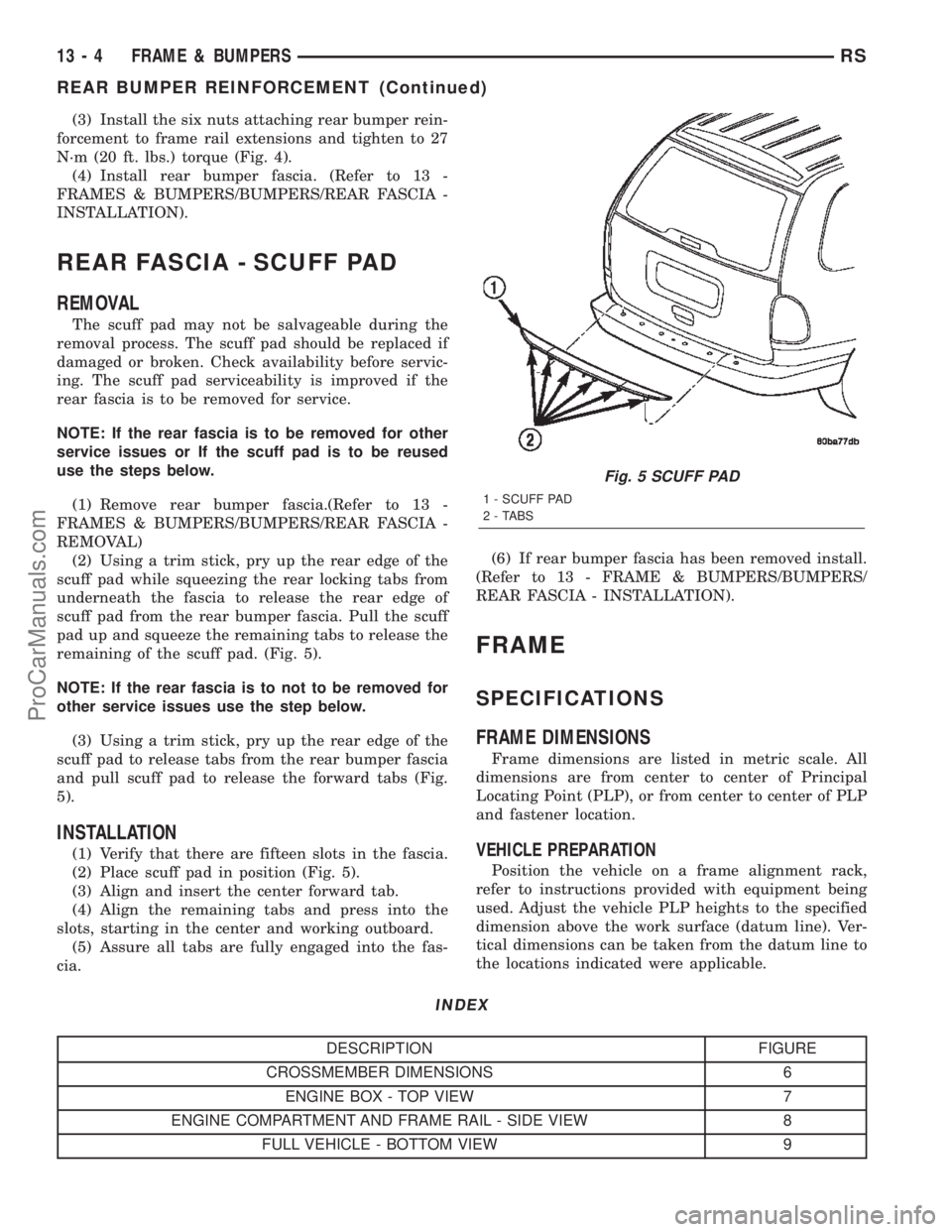
(2) Using a trim stick, pry up the rear edge of the
scuff pad while squeezing the rear locking tabs from
underneath the fascia to release the rear edge of
scuff pad from the rear bumper fascia. Pull the scuff
pad up and squeeze the remaining tabs to release the
remaining of the scuff pad. (Fig. 5).
NOTE: If the rear fascia is to not to be removed for
other service issues use the step below.
(3) Using a trim stick, pry up the rear edge of the
scuff pad to release tabs from the rear bumper fascia
and pull scuff pad to release the forward tabs (Fig.
5).
INSTALLATION
(1) Verify that there are fifteen slots in the fascia.
(2) Place scuff pad in position (Fig. 5).
(3) Align and insert the center forward tab.
(4) Align the remaining tabs and press into the
slots, starting in the center and working outboard.
(5) Assure all tabs are fully engaged into the fas-
cia.(6) If rear bumper fascia has been removed install.
(Refer to 13 - FRAME & BUMPERS/BUMPERS/
REAR FASCIA - INSTALLATION).
FRAME
SPECIFICATIONS
FRAME DIMENSIONS
Frame dimensions are listed in metric scale. All
dimensions are from center to center of Principal
Locating Point (PLP), or from center to center of PLP
and fastener location.
VEHICLE PREPARATION
Position the vehicle on a frame alignment rack,
refer to instructions provided with equipment being
used. Adjust the vehicle PLP heights to the specified
dimension above the work surface (datum line). Ver-
tical dimensions can be taken from the datum line to
the locations indicated were applicable.
INDEX
DESCRIPTION FIGURE
CROSSMEMBER DIMENSIONS 6
ENGINE BOX - TOP VIEW 7
ENGINE COMPARTMENT AND FRAME RAIL - SIDE VIEW 8
FULL VEHICLE - BOTTOM VIEW 9
Fig. 5 SCUFF PAD
1 - SCUFF PAD
2 - TABS
13 - 4 FRAME & BUMPERSRS
REAR BUMPER REINFORCEMENT (Continued)
ProCarManuals.com
Page 1567 of 2399
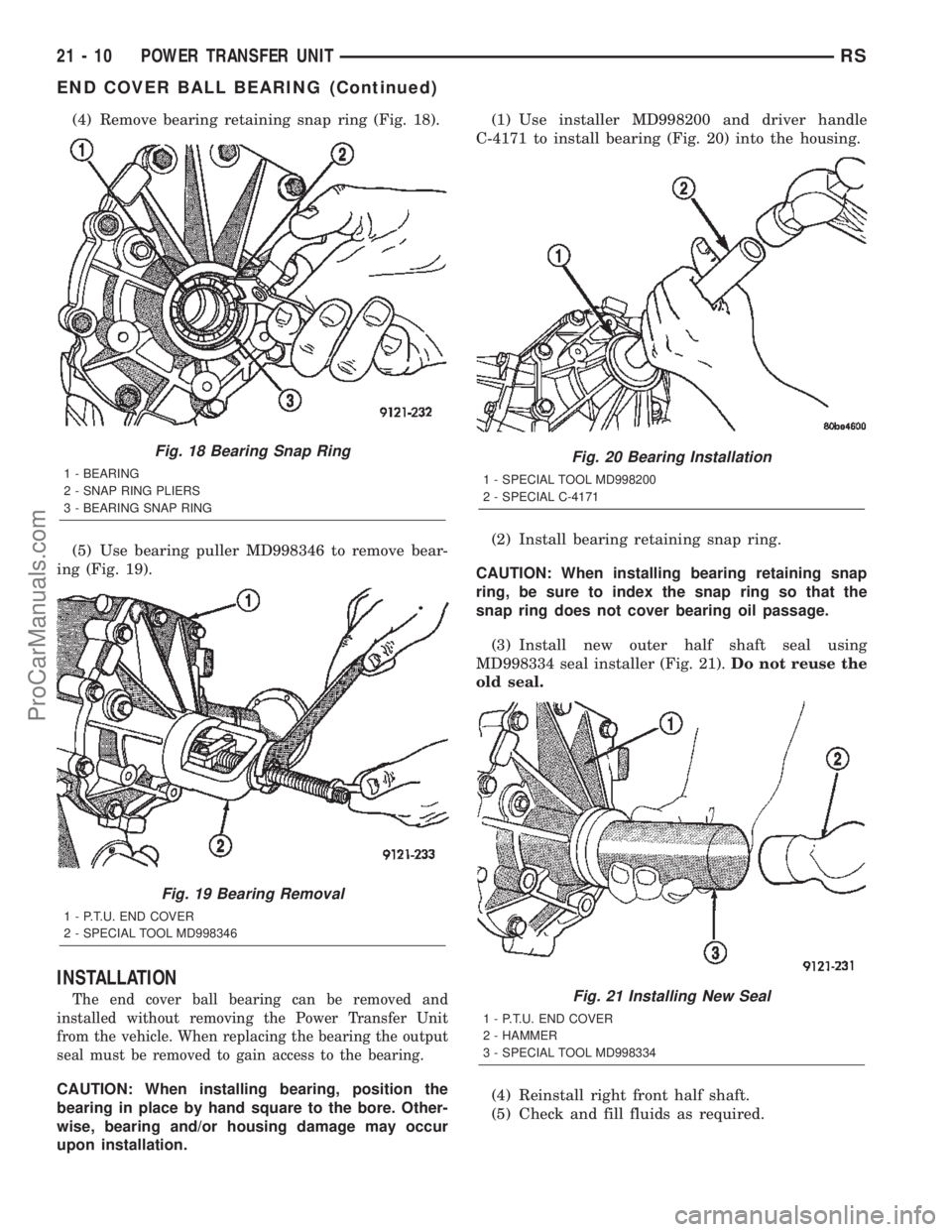
(4) Remove bearing retaining snap ring (Fig. 18).
(5) Use bearing puller MD998346 to remove bear-
ing (Fig. 19).
INSTALLATION
The end cover ball bearing can be removed and
installed without removing the Power Transfer Unit
from the vehicle. When replacing the bearing the output
seal must be removed to gain access to the bearing.
CAUTION: When installing bearing, position the
bearing in place by hand square to the bore. Other-
wise, bearing and/or housing damage may occur
upon installation.(1) Use installer MD998200 and driver handle
C-4171 to install bearing (Fig. 20) into the housing.
(2) Install bearing retaining snap ring.
CAUTION: When installing bearing retaining snap
ring, be sure to index the snap ring so that the
snap ring does not cover bearing oil passage.
(3) Install new outer half shaft seal using
MD998334 seal installer (Fig. 21).Do not reuse the
old seal.
(4) Reinstall right front half shaft.
(5) Check and fill fluids as required.
Fig. 18 Bearing Snap Ring
1 - BEARING
2 - SNAP RING PLIERS
3 - BEARING SNAP RING
Fig. 19 Bearing Removal
1 - P.T.U. END COVER
2 - SPECIAL TOOL MD998346
Fig. 20 Bearing Installation
1 - SPECIAL TOOL MD998200
2 - SPECIAL C-4171
Fig. 21 Installing New Seal
1 - P.T.U. END COVER
2 - HAMMER
3 - SPECIAL TOOL MD998334
21 - 10 POWER TRANSFER UNITRS
END COVER BALL BEARING (Continued)
ProCarManuals.com
Page 1577 of 2399
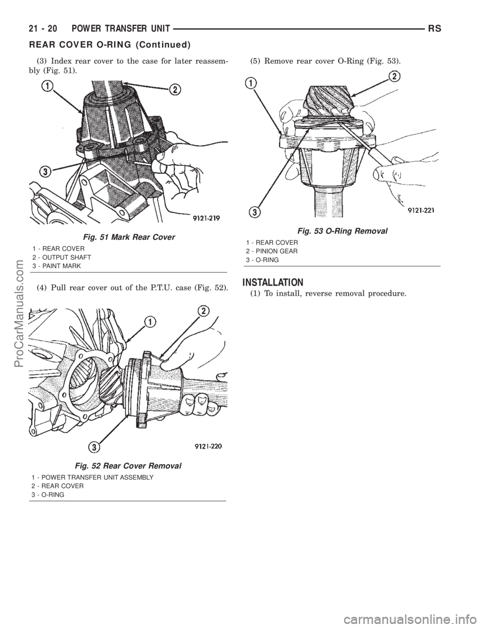
(3) Index rear cover to the case for later reassem-
bly (Fig. 51).
(4) Pull rear cover out of the P.T.U. case (Fig. 52).(5) Remove rear cover O-Ring (Fig. 53).
INSTALLATION
(1) To install, reverse removal procedure.
Fig. 52 Rear Cover Removal
1 - POWER TRANSFER UNIT ASSEMBLY
2 - REAR COVER
3 - O-RING
Fig. 51 Mark Rear Cover
1 - REAR COVER
2 - OUTPUT SHAFT
3 - PAINT MARK
Fig. 53 O-Ring Removal
1 - REAR COVER
2 - PINION GEAR
3 - O-RING
21 - 20 POWER TRANSFER UNITRS
REAR COVER O-RING (Continued)
ProCarManuals.com
Page 1653 of 2399
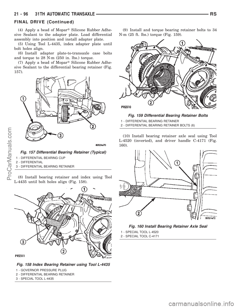
(4) Apply a bead of MopartSilicone Rubber Adhe-
sive Sealant to the adapter plate. Load differential
assembly into position and install adapter plate.
(5) Using Tool L-4435, index adapter plate until
bolt holes align.
(6) Install adapter plate-to-transaxle case bolts
and torque to 28 N´m (250 in. lbs.) torque.
(7) Apply a bead of MopartSilicone Rubber Adhe-
sive Sealant to the differential bearing retainer (Fig.
157).
(8) Install bearing retainer and index using Tool
L-4435 until bolt holes align (Fig. 158).(9) Install and torque bearing retainer bolts to 34
N´m (25 ft. lbs.) torque (Fig. 159).
(10) Install bearing retainer axle seal using Tool
L-4520 (inverted), and driver handle C-4171 (Fig.
160).
Fig. 157 Differential Bearing Retainer (Typical)
1 - DIFFERENTIAL BEARING CUP
2 - DIFFERENTIAL
3 - DIFFERENTIAL BEARING RETAINER
Fig. 158 Index Bearing Retainer using Tool L-4435
1 - GOVERNOR PRESSURE PLUG
2 - DIFFERENTIAL BEARING RETAINER
3 - SPECIAL TOOL L-4435
Fig. 159 Differential Bearing Retainer Bolts
1 - DIFFERENTIAL BEARING RETAINER
2 - DIFFERENTIAL BEARING RETAINER BOLTS (6)
Fig. 160 Install Bearing Retainer Axle Seal
1 - SPECIAL TOOL L-4520
2 - SPECIAL TOOL C-4171
21 - 96 31TH AUTOMATIC TRANSAXLERS
FINAL DRIVE (Continued)
ProCarManuals.com