index CHRYSLER TOWN AND COUNTRY 2002 Service Manual
[x] Cancel search | Manufacturer: CHRYSLER, Model Year: 2002, Model line: TOWN AND COUNTRY, Model: CHRYSLER TOWN AND COUNTRY 2002Pages: 2399, PDF Size: 57.96 MB
Page 56 of 2399
the outer joint of the driveshaft out of the hub/bear-
ing.
(15) Remove the hub/bearing to axle mounting
bolts (Fig. 13).
CAUTION: Corrosion may occur between the hub/
bearing and the axle. If this occurs the hub/bearing
will be difficult to remove from the axle. If the hub/
bearing will not come out of the axle by pulling on
it by hand, do not pound on the hub/bearing to
remove it from the axle. Pounding on the hub/bear-
ing to remove it from the axle will damage the hub/
bearing. This damage will result in noise or failure
of the hub/bearing. To remove a hub/bearing which
is corroded to the axle, lightly tap the disc brake
caliper adapter using a soft faced hammer. This will
remove both the disc brake caliper adapter and
hub/bearing from the axle. The hub/bearing will
then need to be removed from the caliper adapter.
(16) Remove the hub/bearing from the axle. (Fig.
12).
(17) If the disc brake caliper adapter and hub/
bearing were removed as an assembly from the axle
and the hub/bearing cannot be removed from the
adapter by hand, use the following procedure to
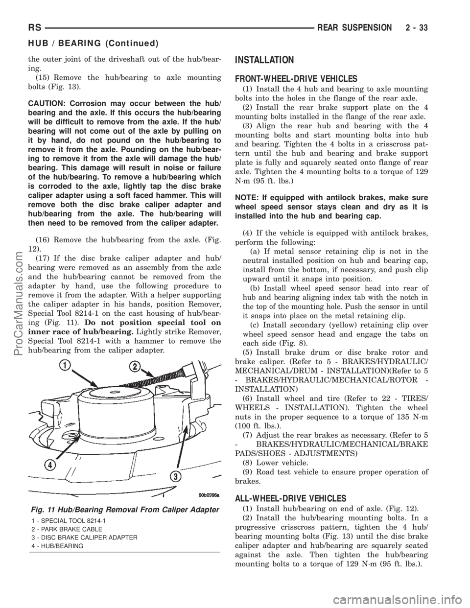
remove it from the adapter. With a helper supporting
the caliper adapter in his hands, position Remover,
Special Tool 8214-1 on the cast housing of hub/bear-
ing (Fig. 11).Do not position special tool on
inner race of hub/bearing.Lightly strike Remover,
Special Tool 8214-1 with a hammer to remove the
hub/bearing from the caliper adapter.INSTALLATION
FRONT-WHEEL-DRIVE VEHICLES
(1) Install the 4 hub and bearing to axle mounting
bolts into the holes in the flange of the rear axle.
(2)
Install the rear brake support plate on the 4
mounting bolts installed in the flange of the rear axle.
(3) Align the rear hub and bearing with the 4
mounting bolts and start mounting bolts into hub
and bearing. Tighten the 4 bolts in a crisscross pat-
tern until the hub and bearing and brake support
plate is fully and squarely seated onto flange of rear
axle. Tighten the 4 mounting bolts to a torque of 129
N´m (95 ft. lbs.)
NOTE: If equipped with antilock brakes, make sure
wheel speed sensor stays clean and dry as it is
installed into the hub and bearing cap.
(4) If the vehicle is equipped with antilock brakes,
perform the following:
(a) If metal sensor retaining clip is not in the
neutral installed position on hub and bearing cap,
install from the bottom, if necessary, and push clip
upward until it snaps into position.
(b)
Install wheel speed sensor head into rear of
hub and bearing aligning index tab with the notch in
the top of the mounting hole. Push the sensor in until
it snaps into place on the metal retaining clip.
(c) Install secondary (yellow) retaining clip over
wheel speed sensor head and engage the tabs on
each side (Fig. 8).
(5) Install brake drum or disc brake rotor and
brake caliper. (Refer to 5 - BRAKES/HYDRAULIC/
MECHANICAL/DRUM - INSTALLATION)(Refer to 5
- BRAKES/HYDRAULIC/MECHANICAL/ROTOR -
INSTALLATION)
(6) Install wheel and tire (Refer to 22 - TIRES/
WHEELS - INSTALLATION). Tighten the wheel
nuts in the proper sequence to a torque of 135 N´m
(100 ft. lbs.).
(7) Adjust the rear brakes as necessary. (Refer to 5
- BRAKES/HYDRAULIC/MECHANICAL/BRAKE
PADS/SHOES - ADJUSTMENTS)
(8) Lower vehicle.
(9) Road test vehicle to ensure proper operation of
brakes.
ALL-WHEEL-DRIVE VEHICLES
(1) Install hub/bearing on end of axle. (Fig. 12).
(2) Install the hub/bearing mounting bolts. In a
progressive crisscross pattern, tighten the 4 hub/
bearing mounting bolts (Fig. 13) until the disc brake
caliper adapter and hub/bearing are squarely seated
against the axle. Then tighten the hub/bearing
mounting bolts to a torque of 129 N´m (95 ft. lbs.).Fig. 11 Hub/Bearing Removal From Caliper Adapter
1 - SPECIAL TOOL 8214-1
2 - PARK BRAKE CABLE
3 - DISC BRAKE CALIPER ADAPTER
4 - HUB/BEARING
RSREAR SUSPENSION2-33
HUB / BEARING (Continued)
ProCarManuals.com
Page 117 of 2399
OPERATION
In order to achieve all-wheel drive operation in
reverse, the overrunning clutch locking functional direc-
tion must be reversible. The bi-directional overrunning
clutch (BOC) changes the operational mode direction
depending on the propeller shaft direction. The propel-
ler shaft rotates in the clockwise (when viewed from the
front) direction when the vehicle is moving forward,
which indexes the BOC to the forward overrunning
position. When the vehicle is in reverse, the propeller
shaft will rotate counter-clockwise and index the BOC
to the reverse overrunning position.
The BOC acts as a mechanical stator. It is active
(transmitting torque), or it is not active and in over-
running mode (not transmitting torque). This ªall or
nothingº approach to torque transfer would cause a
sudden application of all available power to the rear
wheels, which is not desirable. Therefore it is run in
series with a viscous coupler to smooth, dampen, and
limit the transmission of torque to the rear axle and
to prevent a step style torque input to the rear axle.
STEADY STATE, LOW TO MODERATE SPEED, NO
FRONT WHEEL SLIP, FORWARD DIRECTION
During normal driving conditions, (no wheel slip), the
inner shaft (front axle) and outer race (viscous coupler)
are running at different speeds due to the different gear
ratios between the front and rear differentials. In this
condition, the outer race is always spinning faster (over-
driving between 5-32 rpm) than the inner shaft. When
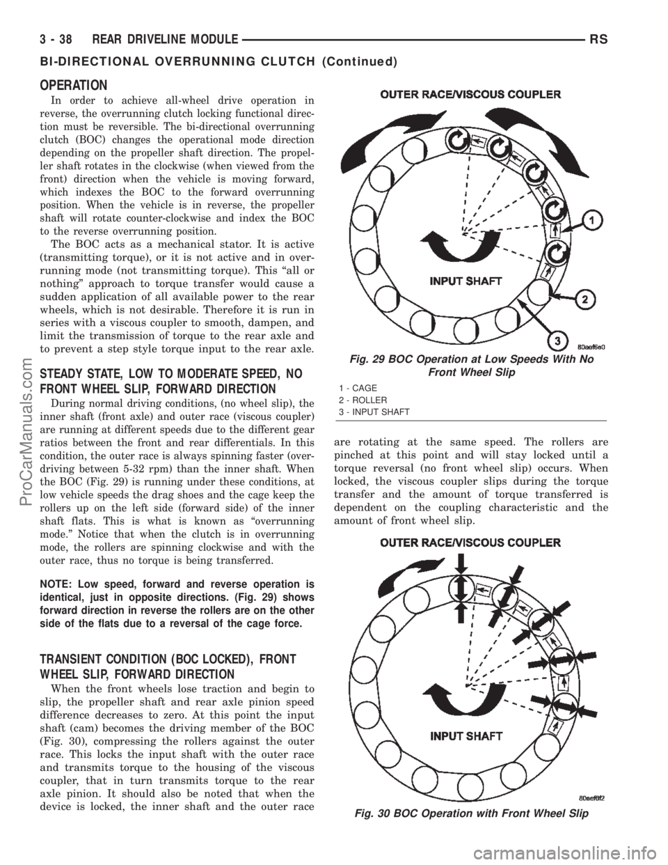
the BOC (Fig. 29) is running under these conditions, at
low vehicle speeds the drag shoes and the cage keep the
rollers up on the left side (forward side) of the inner
shaft flats. This is what is known as ªoverrunning
mode.º Notice that when the clutch is in overrunning
mode, the rollers are spinning clockwise and with the
outer race, thus no torque is being transferred.
NOTE: Low speed, forward and reverse operation is
identical, just in opposite directions. (Fig. 29) shows
forward direction in reverse the rollers are on the other
side of the flats due to a reversal of the cage force.
TRANSIENT CONDITION (BOC LOCKED), FRONT
WHEEL SLIP, FORWARD DIRECTION
When the front wheels lose traction and begin to
slip, the propeller shaft and rear axle pinion speed
difference decreases to zero. At this point the input
shaft (cam) becomes the driving member of the BOC
(Fig. 30), compressing the rollers against the outer
race. This locks the input shaft with the outer race
and transmits torque to the housing of the viscous
coupler, that in turn transmits torque to the rear
axle pinion. It should also be noted that when the
device is locked, the inner shaft and the outer raceare rotating at the same speed. The rollers are
pinched at this point and will stay locked until a
torque reversal (no front wheel slip) occurs. When
locked, the viscous coupler slips during the torque
transfer and the amount of torque transferred is
dependent on the coupling characteristic and the
amount of front wheel slip.
Fig. 29 BOC Operation at Low Speeds With No
Front Wheel Slip
1 - CAGE
2 - ROLLER
3 - INPUT SHAFT
Fig. 30 BOC Operation with Front Wheel Slip
3 - 38 REAR DRIVELINE MODULERS
BI-DIRECTIONAL OVERRUNNING CLUTCH (Continued)
ProCarManuals.com
Page 189 of 2399
ROTOR RUNOUT
On-vehicle rotor runout is the combination of the
individual runout of the hub face and the runout of
the rotor. (The hub and rotor runouts are separable).
To measure rotor runout on the vehicle, first remove
the tire and wheel assembly. Reinstall the wheel
mounting nuts on the studs, tightening the rotor to
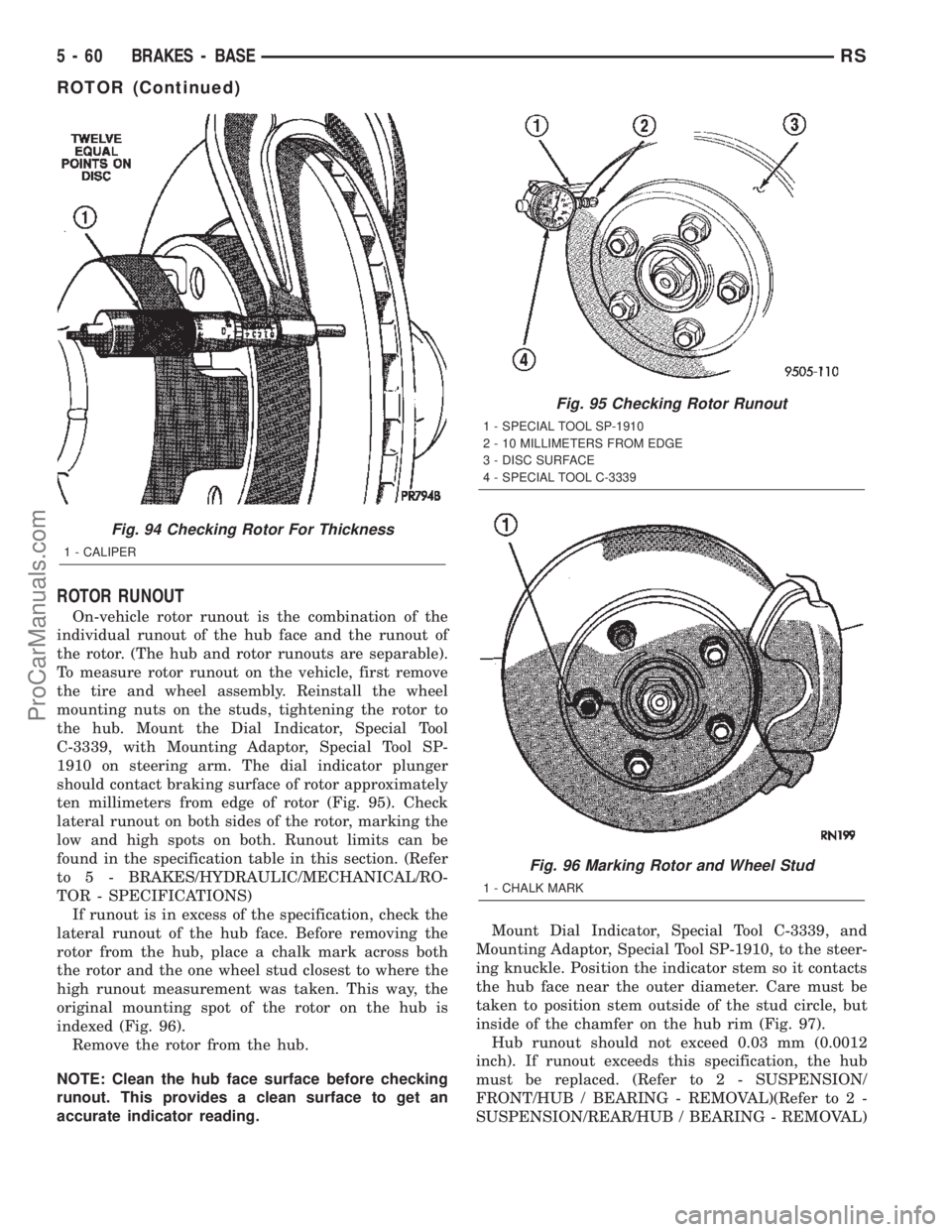
the hub. Mount the Dial Indicator, Special Tool
C-3339, with Mounting Adaptor, Special Tool SP-
1910 on steering arm. The dial indicator plunger
should contact braking surface of rotor approximately
ten millimeters from edge of rotor (Fig. 95). Check
lateral runout on both sides of the rotor, marking the
low and high spots on both. Runout limits can be
found in the specification table in this section. (Refer
to 5 - BRAKES/HYDRAULIC/MECHANICAL/RO-
TOR - SPECIFICATIONS)
If runout is in excess of the specification, check the
lateral runout of the hub face. Before removing the
rotor from the hub, place a chalk mark across both
the rotor and the one wheel stud closest to where the
high runout measurement was taken. This way, the
original mounting spot of the rotor on the hub is
indexed (Fig. 96).
Remove the rotor from the hub.
NOTE: Clean the hub face surface before checking
runout. This provides a clean surface to get an
accurate indicator reading.Mount Dial Indicator, Special Tool C-3339, and
Mounting Adaptor, Special Tool SP-1910, to the steer-
ing knuckle. Position the indicator stem so it contacts
the hub face near the outer diameter. Care must be
taken to position stem outside of the stud circle, but
inside of the chamfer on the hub rim (Fig. 97).
Hub runout should not exceed 0.03 mm (0.0012
inch). If runout exceeds this specification, the hub
must be replaced. (Refer to 2 - SUSPENSION/
FRONT/HUB / BEARING - REMOVAL)(Refer to 2 -
SUSPENSION/REAR/HUB / BEARING - REMOVAL)
Fig. 94 Checking Rotor For Thickness
1 - CALIPER
Fig. 95 Checking Rotor Runout
1 - SPECIAL TOOL SP-1910
2 - 10 MILLIMETERS FROM EDGE
3 - DISC SURFACE
4 - SPECIAL TOOL C-3339
Fig. 96 Marking Rotor and Wheel Stud
1 - CHALK MARK
5 - 60 BRAKES - BASERS
ROTOR (Continued)
ProCarManuals.com
Page 190 of 2399
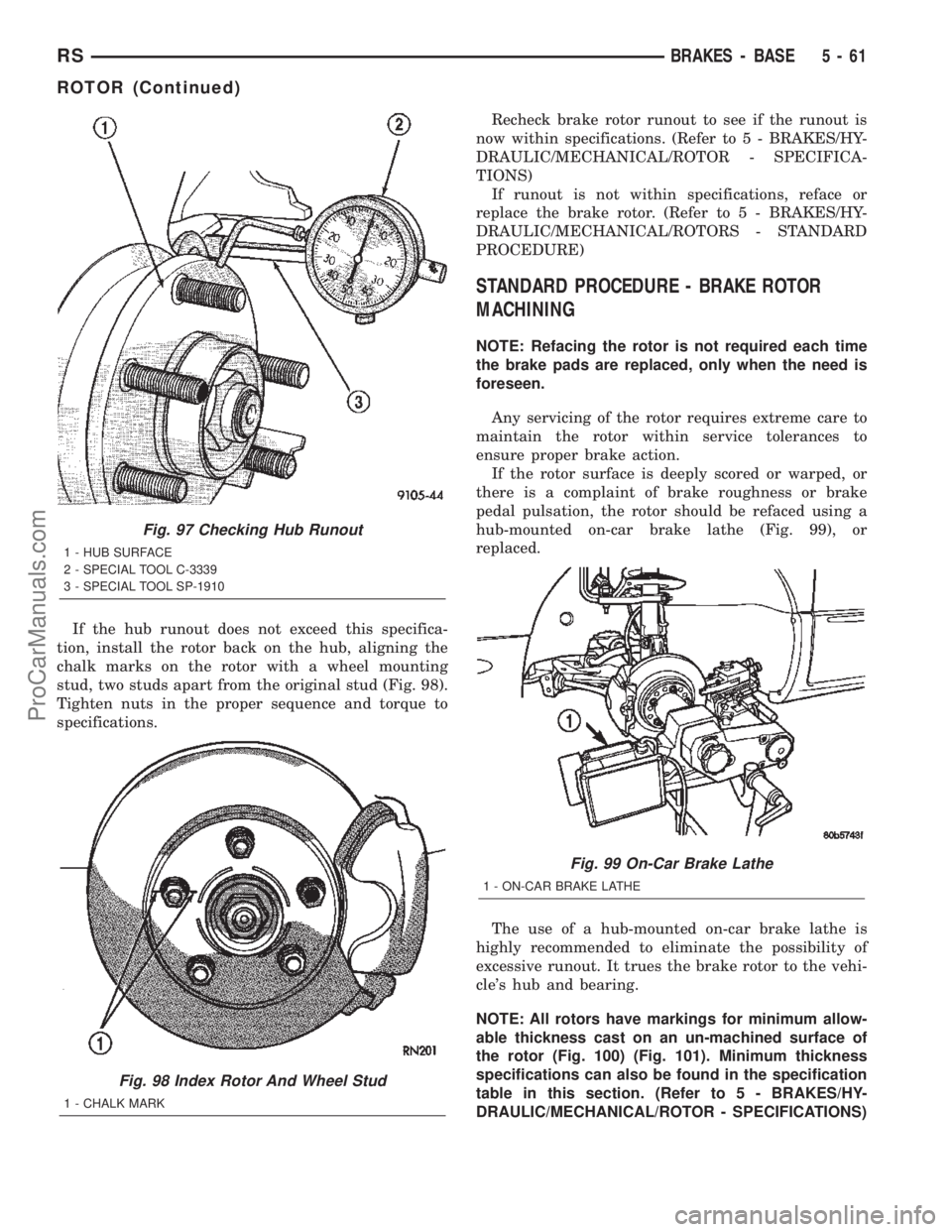
If the hub runout does not exceed this specifica-
tion, install the rotor back on the hub, aligning the
chalk marks on the rotor with a wheel mounting
stud, two studs apart from the original stud (Fig. 98).
Tighten nuts in the proper sequence and torque to
specifications.Recheck brake rotor runout to see if the runout is
now within specifications. (Refer to 5 - BRAKES/HY-
DRAULIC/MECHANICAL/ROTOR - SPECIFICA-
TIONS)
If runout is not within specifications, reface or
replace the brake rotor. (Refer to 5 - BRAKES/HY-
DRAULIC/MECHANICAL/ROTORS - STANDARD
PROCEDURE)
STANDARD PROCEDURE - BRAKE ROTOR
MACHINING
NOTE: Refacing the rotor is not required each time
the brake pads are replaced, only when the need is
foreseen.
Any servicing of the rotor requires extreme care to
maintain the rotor within service tolerances to
ensure proper brake action.
If the rotor surface is deeply scored or warped, or
there is a complaint of brake roughness or brake
pedal pulsation, the rotor should be refaced using a
hub-mounted on-car brake lathe (Fig. 99), or
replaced.
The use of a hub-mounted on-car brake lathe is
highly recommended to eliminate the possibility of
excessive runout. It trues the brake rotor to the vehi-
cle's hub and bearing.
NOTE: All rotors have markings for minimum allow-
able thickness cast on an un-machined surface of
the rotor (Fig. 100) (Fig. 101). Minimum thickness
specifications can also be found in the specification
table in this section. (Refer to 5 - BRAKES/HY-
DRAULIC/MECHANICAL/ROTOR - SPECIFICATIONS)
Fig. 97 Checking Hub Runout
1 - HUB SURFACE
2 - SPECIAL TOOL C-3339
3 - SPECIAL TOOL SP-1910
Fig. 98 Index Rotor And Wheel Stud
1 - CHALK MARK
Fig. 99 On-Car Brake Lathe
1 - ON-CAR BRAKE LATHE
RSBRAKES - BASE5-61
ROTOR (Continued)
ProCarManuals.com
Page 211 of 2399
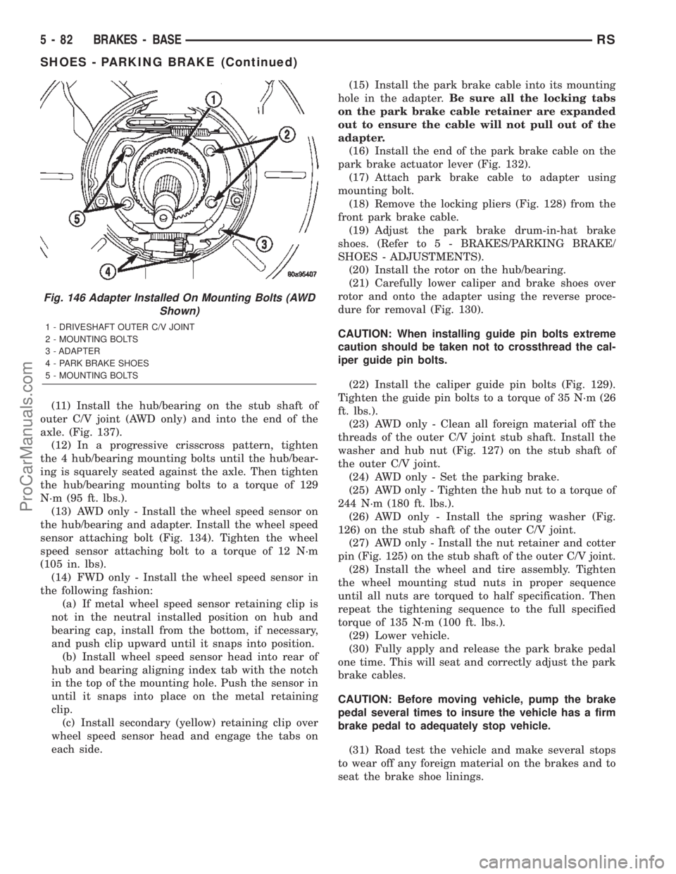
(11) Install the hub/bearing on the stub shaft of
outer C/V joint (AWD only) and into the end of the
axle. (Fig. 137).
(12) In a progressive crisscross pattern, tighten
the 4 hub/bearing mounting bolts until the hub/bear-
ing is squarely seated against the axle. Then tighten
the hub/bearing mounting bolts to a torque of 129
N´m (95 ft. lbs.).
(13) AWD only - Install the wheel speed sensor on
the hub/bearing and adapter. Install the wheel speed
sensor attaching bolt (Fig. 134). Tighten the wheel
speed sensor attaching bolt to a torque of 12 N´m
(105 in. lbs).
(14) FWD only - Install the wheel speed sensor in
the following fashion:
(a) If metal wheel speed sensor retaining clip is
not in the neutral installed position on hub and
bearing cap, install from the bottom, if necessary,
and push clip upward until it snaps into position.
(b) Install wheel speed sensor head into rear of
hub and bearing aligning index tab with the notch
in the top of the mounting hole. Push the sensor in
until it snaps into place on the metal retaining
clip.
(c) Install secondary (yellow) retaining clip over
wheel speed sensor head and engage the tabs on
each side.(15) Install the park brake cable into its mounting
hole in the adapter.Be sure all the locking tabs
on the park brake cable retainer are expanded
out to ensure the cable will not pull out of the
adapter.
(16) Install the end of the park brake cable on the
park brake actuator lever (Fig. 132).
(17) Attach park brake cable to adapter using
mounting bolt.
(18) Remove the locking pliers (Fig. 128) from the
front park brake cable.
(19) Adjust the park brake drum-in-hat brake
shoes. (Refer to 5 - BRAKES/PARKING BRAKE/
SHOES - ADJUSTMENTS).
(20) Install the rotor on the hub/bearing.
(21) Carefully lower caliper and brake shoes over
rotor and onto the adapter using the reverse proce-
dure for removal (Fig. 130).
CAUTION: When installing guide pin bolts extreme
caution should be taken not to crossthread the cal-
iper guide pin bolts.
(22) Install the caliper guide pin bolts (Fig. 129).
Tighten the guide pin bolts to a torque of 35 N´m (26
ft. lbs.).
(23) AWD only - Clean all foreign material off the
threads of the outer C/V joint stub shaft. Install the
washer and hub nut (Fig. 127) on the stub shaft of
the outer C/V joint.
(24) AWD only - Set the parking brake.
(25) AWD only - Tighten the hub nut to a torque of
244 N´m (180 ft. lbs.).
(26) AWD only - Install the spring washer (Fig.
126) on the stub shaft of the outer C/V joint.
(27) AWD only - Install the nut retainer and cotter
pin (Fig. 125) on the stub shaft of the outer C/V joint.
(28) Install the wheel and tire assembly. Tighten
the wheel mounting stud nuts in proper sequence
until all nuts are torqued to half specification. Then
repeat the tightening sequence to the full specified
torque of 135 N´m (100 ft. lbs.).
(29) Lower vehicle.
(30) Fully apply and release the park brake pedal
one time. This will seat and correctly adjust the park
brake cables.
CAUTION: Before moving vehicle, pump the brake
pedal several times to insure the vehicle has a firm
brake pedal to adequately stop vehicle.
(31) Road test the vehicle and make several stops
to wear off any foreign material on the brakes and to
seat the brake shoe linings.
Fig. 146 Adapter Installed On Mounting Bolts (AWD
Shown)
1 - DRIVESHAFT OUTER C/V JOINT
2 - MOUNTING BOLTS
3 - ADAPTER
4 - PARK BRAKE SHOES
5 - MOUNTING BOLTS
5 - 82 BRAKES - BASERS
SHOES - PARKING BRAKE (Continued)
ProCarManuals.com
Page 221 of 2399
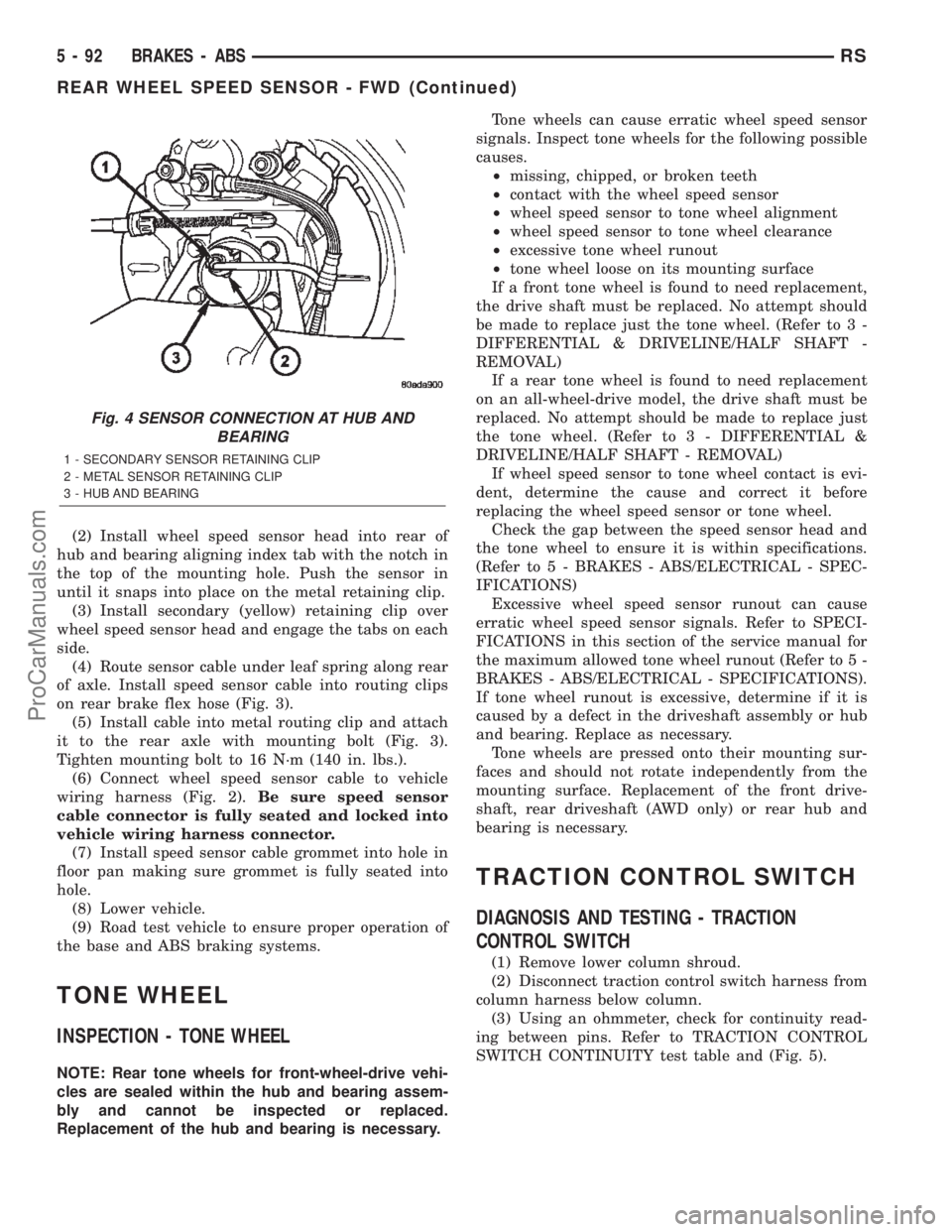
(2) Install wheel speed sensor head into rear of
hub and bearing aligning index tab with the notch in
the top of the mounting hole. Push the sensor in
until it snaps into place on the metal retaining clip.
(3) Install secondary (yellow) retaining clip over
wheel speed sensor head and engage the tabs on each
side.
(4) Route sensor cable under leaf spring along rear
of axle. Install speed sensor cable into routing clips
on rear brake flex hose (Fig. 3).
(5) Install cable into metal routing clip and attach
it to the rear axle with mounting bolt (Fig. 3).
Tighten mounting bolt to 16 N´m (140 in. lbs.).
(6) Connect wheel speed sensor cable to vehicle
wiring harness (Fig. 2).Be sure speed sensor
cable connector is fully seated and locked into
vehicle wiring harness connector.
(7) Install speed sensor cable grommet into hole in
floor pan making sure grommet is fully seated into
hole.
(8) Lower vehicle.
(9) Road test vehicle to ensure proper operation of
the base and ABS braking systems.
TONE WHEEL
INSPECTION - TONE WHEEL
NOTE: Rear tone wheels for front-wheel-drive vehi-
cles are sealed within the hub and bearing assem-
bly and cannot be inspected or replaced.
Replacement of the hub and bearing is necessary.Tone wheels can cause erratic wheel speed sensor
signals. Inspect tone wheels for the following possible
causes.
²missing, chipped, or broken teeth
²contact with the wheel speed sensor
²wheel speed sensor to tone wheel alignment
²wheel speed sensor to tone wheel clearance
²excessive tone wheel runout
²tone wheel loose on its mounting surface
If a front tone wheel is found to need replacement,
the drive shaft must be replaced. No attempt should
be made to replace just the tone wheel. (Refer to 3 -
DIFFERENTIAL & DRIVELINE/HALF SHAFT -
REMOVAL)
If a rear tone wheel is found to need replacement
on an all-wheel-drive model, the drive shaft must be
replaced. No attempt should be made to replace just
the tone wheel. (Refer to 3 - DIFFERENTIAL &
DRIVELINE/HALF SHAFT - REMOVAL)
If wheel speed sensor to tone wheel contact is evi-
dent, determine the cause and correct it before
replacing the wheel speed sensor or tone wheel.
Check the gap between the speed sensor head and
the tone wheel to ensure it is within specifications.
(Refer to 5 - BRAKES - ABS/ELECTRICAL - SPEC-
IFICATIONS)
Excessive wheel speed sensor runout can cause
erratic wheel speed sensor signals. Refer to SPECI-
FICATIONS in this section of the service manual for
the maximum allowed tone wheel runout (Refer to 5 -
BRAKES - ABS/ELECTRICAL - SPECIFICATIONS).
If tone wheel runout is excessive, determine if it is
caused by a defect in the driveshaft assembly or hub
and bearing. Replace as necessary.
Tone wheels are pressed onto their mounting sur-
faces and should not rotate independently from the
mounting surface. Replacement of the front drive-
shaft, rear driveshaft (AWD only) or rear hub and
bearing is necessary.
TRACTION CONTROL SWITCH
DIAGNOSIS AND TESTING - TRACTION
CONTROL SWITCH
(1) Remove lower column shroud.
(2) Disconnect traction control switch harness from
column harness below column.
(3) Using an ohmmeter, check for continuity read-
ing between pins. Refer to TRACTION CONTROL
SWITCH CONTINUITY test table and (Fig. 5).
Fig. 4 SENSOR CONNECTION AT HUB AND
BEARING
1 - SECONDARY SENSOR RETAINING CLIP
2 - METAL SENSOR RETAINING CLIP
3 - HUB AND BEARING
5 - 92 BRAKES - ABSRS
REAR WHEEL SPEED SENSOR - FWD (Continued)
ProCarManuals.com
Page 304 of 2399
COOLANT
DESCRIPTION
Coolant flows through the engine water jackets
and cylinder heads absorbing heat produced by the
engine during operation. The coolant carries heat to
the radiator and heater core. Here it is transferred to
ambient air passing through the radiator and heater
core fins.
The required ethylene-glycol (antifreeze) and water
mixture depends upon the climate and vehicle oper-
ating conditions. The recommended mixture of 50/50
ethylene-glycol and water will provide protection
against freezing to -37 deg. C (-35 deg. F). The anti-
freeze concentrationmust alwaysbe a minimum of
44 percent, year-round in all climates.If percentage
is lower than 44 percent, engine parts may be
eroded by cavitation, and cooling system com-
ponents may be severely damaged by corrosion.
Maximum protection against freezing is provided
with a 68 percent antifreeze concentration, which
prevents freezing down to -67.7 deg. C (-90 deg. F). A
higher percentage will freeze at a warmer tempera-
ture. Also, a higher percentage of antifreeze can
cause the engine to overheat because the specific
heat of antifreeze is lower than that of water.
100 Percent Ethylene-GlycolÐShould Not Be Used in
Chrysler Vehicles
Use of 100 percent ethylene-glycol will cause for-
mation of additive deposits in the system, as the cor-
rosion inhibitive additives in ethylene-glycol require
the presence of water to dissolve. The deposits act as
insulation, causing temperatures to rise to as high as
149 deg. C (300 deg. F). This temperature is hot
enough to melt plastic and soften solder. The
increased temperature can result in engine detona-
tion. In addition, 100 percent ethylene-glycol freezes
at -22 deg. C (-8 deg. F ).
Propylene-glycol FormulationsÐShould Not Be Used in
Chrysler Vehicles
Propylene-glycol formulations do not meet
Chrysler coolant specifications.It's overall effec-
tive temperature range is smaller than that of ethyl-
ene-glycol. The freeze point of 50/50 propylene-glycol
and water is -32 deg. C (-26 deg. F). 5 deg. C higher
than ethylene-glycol's freeze point. The boiling point
(protection against summer boil-over) of propylene-
glycol is 125 deg. C (257 deg.F)at96.5 kPa (14 psi),
compared to 128 deg. C (263 deg. F) for ethylene-gly-
col. Use of propylene-glycol can result in boil-over or
freeze-up in Chrysler vehicles, which are designed for
ethylene-glycol. Propylene glycol also has poorer heat
transfer characteristics than ethylene glycol. Thiscan increase cylinder head temperatures under cer-
tain conditions.
Propylene-glycol/Ethylene-glycol MixturesÐShould Not Be
Used in Chrysler Vehicles
Propylene-glycol/ethylene-glycol Mixtures can
cause the destabilization of various corrosion inhibi-
tors, causing damage to the various cooling system
components. Also, once ethylene-glycol and propy-
lene-glycol based coolants are mixed in the vehicle,
conventional methods of determining freeze point will
not be accurate. Both the refractive index and spe-
cific gravity differ between ethylene glycol and propy-
lene glycol.
CAUTION: Richer antifreeze mixtures cannot be
measured with normal field equipment and can
cause problems associated with 100 percent ethyl-
ene-glycol.
DIAGNOSIS AND TESTING - COOLANT
CONCENTRATION TESTING
Coolant concentration should be checked when any
additional coolant was added to system or after a
coolant drain, flush and refill. The coolant mixture
offers optimum engine cooling and protection against
corrosion when mixed to a freeze point of -37ÉC
(-34ÉF) to -59ÉC (-50ÉF). The use of a hydrometer or a
refractometer can be used to test coolant concentra-
tion.
A hydrometer will test the amount of glycol in a
mixture by measuring the specific gravity of the mix-
ture. The higher the concentration of ethylene glycol,
the larger the number of balls that will float, and
higher the freeze protection (up to a maximum of
60% by volume glycol).
A refractometer will test the amount of glycol in a
coolant mixture by measuring the amount a beam of
light bends as it passes through the fluid.
Some coolant manufactures use other types of gly-
cols into their coolant formulations. Propylene glycol
is the most common new coolant. However, propylene
glycol based coolants do not provide the same freez-
ing protection and corrosion protection and is not rec-
ommended.
CAUTION: Do not mix types of coolantÐcorrosion
protection will be severely reduced.
RGENGINE7a-15
ProCarManuals.com
Page 366 of 2399

CLUTCH VOLUME INDEX (CVI)
An important function of the TCM is to monitor
Clutch Volume Index (CVI). CVIs represent the vol-
ume of fluid needed to compress a clutch pack.
The TCM monitors gear ratio changes by monitor-
ing the Input and Output Speed Sensors. The Input,
or Turbine Speed Sensor sends an electrical signal to
the TCM that represents input shaft rpm. The Out-
put Speed Sensor provides the TCM with output
shaft speed information.
By comparing the two inputs, the TCM can deter-
mine transaxle gear ratio. This is important to the
CVI calculation because the TCM determines CVIs
by monitoring how long it takes for a gear change to
occur (Fig. 15).
Gear ratios can be determined by using the DRB
Scan Tool and reading the Input/Output Speed Sen-
sor values in the ªMonitorsº display. Gear ratio can
be obtained by dividing the Input Speed Sensor value
by the Output Speed Sensor value.
For example, if the input shaft is rotating at 1000
rpm and the output shaft is rotating at 500 rpm,
then the TCM can determine that the gear ratio is
2:1. In direct drive (3rd gear), the gear ratio changes
to 1:1. The gear ratio changes as clutches are applied
and released. By monitoring the length of time it
takes for the gear ratio to change following a shift
request, the TCM can determine the volume of fluid
used to apply or release a friction element.
The volume of transmission fluid needed to apply
the friction elements are continuously updated for
adaptive controls. As friction material wears, the vol-
ume of fluid need to apply the element increases.
Certain mechanical problems within the clutch
assemblies (broken return springs, out of position
snap rings, excessive clutch pack clearance, improper
assembly, etc.) can cause inadequate or out-of-rangeclutch volumes. Also, defective Input/Output Speed
Sensors and wiring can cause these conditions. The
following chart identifies the appropriate clutch vol-
umes and when they are monitored/updated:
CLUTCH VOLUMES
ClutchWhen Updated
Proper Clutch
Volume
Shift Sequence Oil Temperature Throttle Angle
L/R2-1 or 3-1 coast
downshift>70É <5É 35to83
2/4 1-2 shift
> 110É5 - 54É20 to 77
OD 2-3 shift 48 to 150
UD 4-3 or 4-2 shift > 5É 24 to 70
Fig. 15 Example of CVI Calculation
1 - OUTPUT SPEED SENSOR
2 - OUTPUT SHAFT
3 - CLUTCH PACK
4 - SEPARATOR PLATE
5 - FRICTION DISCS
6 - INPUT SHAFT
7 - INPUT SPEED SENSOR
8 - PISTON AND SEAL
RSELECTRONIC CONTROL MODULES8E-29
TRANSMISSION CONTROL MODULE (Continued)
ProCarManuals.com
Page 391 of 2399
(1) Turn the ignition switch to the Off position. Be
certain that all electrical accessories are turned off.
(2) Remove the nut with washer that secures the
battery hold down bracket to the battery tray and
support unit.
(3) Remove the battery hold down bracket from
the battery tray and support unit.
INSTALLATION
(1) Install the battery hold down bracket in the
battery tray and support unit.
(2) Install the nut with washer that secures the
battery hold down bracket to the battery tray and
support unit. Torque to 20 N´m (180 in. lbs.).
BATTERY CABLES
DESCRIPTION
The battery cables are large gauge, stranded cop-
per wires sheathed within a heavy plastic or syn-
thetic rubber insulating jacket. The wire used in the
battery cables combines excellent flexibility and reli-
ability with high electrical current carrying capacity.
Refer toWiring Diagramsin the index of this ser-
vice manual for the location of the proper battery
cable wire gauge information.
A clamping type female battery terminal made of
stamped metal is attached to one end of the battery
cable wire. A square headed pinch-bolt and hex nut
are installed at the open end of the female battery
terminal clamp. Large eyelet type terminals are
crimped onto the opposite end of the battery cable
wire and then solder-dipped. The battery positive
cable wires have a red insulating jacket to provide
visual identification and feature a larger female bat-
tery terminal clamp to allow connection to the larger
battery positive terminal post. The battery negative
cable wires have a black insulating jacket and a
smaller female battery terminal clamp.
The battery cables cannot be repaired and, if dam-
aged or faulty they must be replaced. Both the bat-
tery positive and negative cables are available for
service replacement only as a unit with the battery
wire harness, which may include portions of the wir-
ing circuits for the generator and other components
on some models. Refer toWiring Diagramsin the
index of this service manual for the location of more
information on the various wiring circuits included in
the battery wire harness for the vehicle being ser-
viced.
OPERATION
The battery cables connect the battery terminal
posts to the vehicle electrical system. These cables
also provide a path back to the battery for electricalcurrent generated by the charging system for restor-
ing the voltage potential of the battery. The female
battery terminal clamps on the ends of the battery
cable wires provide a strong and reliable connection
of the battery cable to the battery terminal posts.
The terminal pinch bolts allow the female terminal
clamps to be tightened around the male terminal
posts on the top of the battery. The eyelet terminals
secured to the opposite ends of the battery cable
wires from the female battery terminal clamps pro-
vide secure and reliable connection of the battery
cables to the vehicle electrical system.
The battery positive cable terminal clamp is
attached to the ends of two wires. One wire has an
eyelet terminal that connects the battery positive
cable to the B(+) terminal stud of the Integrated
Power Module (IPM), and the other wire has an eye-
let terminal that connects the battery positive cable
to the B(+) terminal stud of the engine starter motor
solenoid. The battery negative cable terminal clamp
is also attached to the ends of two wires. One wire
has an eyelet terminal that connects the battery neg-
ative cable to the vehicle powertrain through a stud
on the left side of the engine cylinder block. The
other wire has an eyelet terminal that connects the
battery negative cable to the vehicle body through a
ground screw on the left front fender inner shield,
near the battery.
DIAGNOSIS AND TESTING - BATTERY CABLE
A voltage drop test will determine if there is exces-
sive resistance in the battery cable terminal connec-
tions or the battery cable. If excessive resistance is
found in the battery cable connections, the connec-
tion point should be disassembled, cleaned of all cor-
rosion or foreign material, then reassembled.
Following reassembly, check the voltage drop for the
battery cable connection and the battery cable again
to confirm repair.
When performing the voltage drop test, it is impor-
tant to remember that the voltage drop is giving an
indication of the resistance between the two points at
which the voltmeter probes are attached.EXAM-
PLE:When testing the resistance of the battery pos-
itive cable, touch the voltmeter leads to the battery
positive cable terminal clamp and to the battery pos-
itive cable eyelet terminal at the starter solenoid
B(+) terminal stud. If you probe the battery positive
terminal post and the battery positive cable eyelet
terminal at the starter solenoid B(+) terminal stud,
you are reading the combined voltage drop in the
battery positive cable terminal clamp-to-terminal
post connection and the battery positive cable.
8F - 16 BATTERY SYSTEMRS
BATTERY HOLDDOWN (Continued)
ProCarManuals.com
Page 427 of 2399
battery movement during the most extreme vehicle
operation conditions. Periodic removal and lubrica-
tion of the battery holddown hardware is recom-
mended to prevent hardware seizure at a later date.
NOTE: Never operate a vehicle without a battery
holddown device properly installed. Damage to the
vehicle, components and battery could result.
REMOVAL
All of the battery hold down hardware can be ser-
viced without removal of the battery or the battery
tray and support unit.
(1) Turn the ignition switch to the Off position. Be
certain that all electrical accessories are turned off.
(2) Remove the nut with washer that secures the
battery hold down bracket to the battery tray and
support unit.
(3) Remove the battery hold down bracket from
the battery tray and support unit.
INSTALLATION
(1) Install the battery hold down bracket in the
battery tray and support unit.
(2) Install the nut with washer that secures the
battery hold down bracket to the battery tray and
support unit. Torque to 20 N´m (180 in. lbs.).
BATTERY CABLES
DESCRIPTION
The battery cables are large gauge, stranded cop-
per wires sheathed within a heavy plastic or syn-
thetic rubber insulating jacket. The wire used in the
battery cables combines excellent flexibility and reli-
ability with high electrical current carrying capacity.
Refer toWiring Diagramsin the index of this ser-
vice manual for the location of the proper battery
cable wire gauge information.
A clamping type female battery terminal made of
stamped metal is attached to one end of the battery
cable wire. A square headed pinch-bolt and hex nut
are installed at the open end of the female battery
terminal clamp. Large eyelet type terminals are
crimped onto the opposite end of the battery cable
wire and then solder-dipped. The battery positive
cable wires have a red insulating jacket to provide
visual identification and feature a larger female bat-
tery terminal clamp to allow connection to the larger
battery positive terminal post. The battery negative
cable wires have a black insulating jacket and a
smaller female battery terminal clamp.
The battery cables cannot be repaired and, if dam-
aged or faulty they must be replaced. Both the bat-
tery positive and negative cables are available forservice replacement only as a unit with the battery
wire harness, which may include portions of the wir-
ing circuits for the generator and other components
on some models. Refer toWiring Diagramsin the
index of this service manual for the location of more
information on the various wiring circuits included in
the battery wire harness for the vehicle being ser-
viced.
OPERATION
The battery cables connect the battery terminal
posts to the vehicle electrical system. These cables
also provide a path back to the battery for electrical
current generated by the charging system for restor-
ing the voltage potential of the battery. The female
battery terminal clamps on the ends of the battery
cable wires provide a strong and reliable connection
of the battery cable to the battery terminal posts.
The terminal pinch bolts allow the female terminal
clamps to be tightened around the male terminal
posts on the top of the battery. The eyelet terminals
secured to the opposite ends of the battery cable
wires from the female battery terminal clamps pro-
vide secure and reliable connection of the battery
cables to the vehicle electrical system.
The battery positive cable terminal clamp is
attached to the ends of two wires. One wire has an
eyelet terminal that connects the battery positive
cable to the B(+) terminal stud of the Integrated
Power Module (IPM), and the other wire has an eye-
let terminal that connects the battery positive cable
to the B(+) terminal stud of the engine starter motor
solenoid. The battery negative cable terminal clamp
is also attached to the ends of two wires. One wire
has an eyelet terminal that connects the battery neg-
ative cable to the vehicle powertrain through a stud
on the left side of the engine cylinder block. The
other wire has an eyelet terminal that connects the
battery negative cable to the vehicle body through a
ground screw on the left front fender inner shield,
near the battery.
DIAGNOSIS AND TESTING - BATTERY CABLE
A voltage drop test will determine if there is exces-
sive resistance in the battery cable terminal connec-
tions or the battery cable. If excessive resistance is
found in the battery cable connections, the connec-
tion point should be disassembled, cleaned of all cor-
rosion or foreign material, then reassembled.
Following reassembly, check the voltage drop for the
battery cable connection and the battery cable again
to confirm repair.
When performing the voltage drop test, it is impor-
tant to remember that the voltage drop is giving an
indication of the resistance between the two points at
which the voltmeter probes are attached.EXAM-
8Fa - 16 BATTERY SYSTEMRG
BATTERY HOLDDOWN (Continued)
ProCarManuals.com