check engine CHRYSLER TOWN AND COUNTRY 2002 Workshop Manual
[x] Cancel search | Manufacturer: CHRYSLER, Model Year: 2002, Model line: TOWN AND COUNTRY, Model: CHRYSLER TOWN AND COUNTRY 2002Pages: 2399, PDF Size: 57.96 MB
Page 339 of 2399
ELECTRONIC CONTROL
MODULES
STANDARD PROCEDURE - PCM/SKIM
PROGRAMMING
NOTE: Before replacing the PCM for a failed driver,
control circuit or ground circuit, be sure to check
the related component/circuit integrity for failures
not detected due to a double fault in the circuit.
Most PCM driver/control circuit failures are caused
by internal component failures (i.e. relay and sole-
noids) and shorted circuits (i.e. pull-ups, drivers
and switched circuits). These failures are difficult to
detect when a double fault has occurred and only
one DTC has set.
When a PCM (SBEC) and the SKIM are replaced
at the same time perform the following steps in
order:
(1) Program the new PCM (SBEC)
(2) Program the new SKIM
(3) Replace all ignition keys and program them to
the new SKIM.
PROGRAMMING THE PCM (SBEC)
The SKIS Secret Key is an ID code that is unique
to each SKIM. This code is programmed and stored
in the SKIM, PCM and transponder chip (ignition
keys). When replacing the PCM it is necessary to
program the secret key into the new PCM using the
DRB III. Perform the following steps to program the
secret key into the PCM.
(1) Turn the ignition switch on (transmission in
park/neutral).
(2) Use the DRB III and select THEFT ALARM,
SKIM then MISCELLANEOUS.
(3) Select PCM REPLACED (GAS ENGINE).
(4) Enter secured access mode by entering the
vehicle four-digit PIN.
(5) Select ENTER to update PCM VIN.
NOTE: If three attempts are made to enter secure
access mode using an incorrect PIN, secured
access mode will be locked out for one hour. To
exit this lockout mode, turn the ignition to the RUN
position for one hour then enter the correct PIN.
(Ensure all accessories are turned off. Also monitor
the battery state and connect a battery charger if
necessary).
(6) Press ENTER to transfer the secret key (the
SKIM will send the secret key to the PCM).
(7) Press Page Back to get to the Select System
menu and select ENGINE, MISCELLANEOUS, and
SRI MEMORY CHECK.(8) The DRB III will ask, Is odometer reading
between XX and XX? Select the YES or NO button on
the DRB III. If NO is selected, the DRB III will read,
Enter odometer Reading
the odometer reading from the Instrument Panel and
press ENTER.
PROGRAMMING THE SKIM
(1) Turn the ignition switch on (transmission in
park/neutral).
(2) Use the DRB III and select THEFT ALARM,
SKIM then MISCELLANEOUS.
(3) Select PCM REPLACED (GAS ENGINE).
(4) Program the vehicle four-digit PIN into SKIM.
(5) Select COUNTRY CODE and enter the correct
country.
NOTE: Be sure to enter the correct country code. If
the incorrect country code is programmed into
SKIM, the SKIM must be replaced.
(6) Select YES to update VIN (the SKIM will learn
the VIN from the PCM).
(7) Press ENTER to transfer the secret key (the
PCM will send the secret key to the SKIM).
(8) Program ignition keys to SKIM.
NOTE: If the PCM and the SKIM are replaced at the
same time, all vehicle keys will need to be replaced
and programmed to the new SKIM.
PROGRAMMING IGNITION KEYS TO THE SKIM
(1) Turn the ignition switch on (transmission in
park/neutral).
(2) Use the DRB III and select THEFT ALARM,
SKIM then MISCELLANEOUS.
(3) Select PROGRAM IGNITION KEY'S.
(4) Enter secured access mode by entering the
vehicle four-digit PIN.
NOTE: A maximum of eight keys can be learned to
each SKIM. Once a key is learned to a SKIM it (the
key) cannot be transferred to another vehicle.
If ignition key programming is unsuccessful, the
DRB III will display one of the following messages:
Programming Not Attempted - The DRB III
attempts to read the programmed key status and
there are no keys programmed into SKIM memory.
Programming Key Failed (Possible Used Key From
Wrong Vehicle) - SKIM is unable to program key due
to one of the following:
²faulty ignition key transponder
²ignition key is programmed to another vehicle.
8 Keys Already Learned, Programming Not Done -
SKIM transponder ID memory is full.
8E - 2 ELECTRONIC CONTROL MODULESRS
ProCarManuals.com
Page 345 of 2399
²Back-Up switch
²Brake Fluid Level
²B+ Connection Detection
²Engine Crank Signal (Diesel Engine Vehicles)
²Horn Input
²Ignition Switch Start Only
²Ignition Switch Run and Start Only
²Stop Lamp Sense
²Washer Fluid Level
²Windshield Wiper Park
DIAGNOSIS AND TESTING - FRONT CONTROL
MODULE
The Front Control Module (FCM) is a printed cir-
cuit board based module with a on-board micro-pro-
cessor. The FCM interfaces with other electronic
modules in the vehicle via the Programmable Com-
munications Interface (PCI) data bus. In order to
obtain conclusive testing the PCI data bus and all of
the electronic modules that provide inputs to, or
receive outputs from the FCM must be checked. All
PCI communication faults must be resolved prior to
further diagnosing any front control module related
issues.
The FCM was designed to be diagnosed with an
appropriate diagnostic scan tool, such as the DRB
IIIt. The most reliable, efficient, and accurate means
to diagnose the front control module requires the use
of a DRB IIItscan tool and the proper Body Diag-
nostic Procedures manual.
Before any testing of the FCM is attempted, the
battery should be fully charged and all wire harness
and ground connections inspected around the affected
areas on the vehicle.
REMOVAL
(1) Disconnect the positive and negative battery
cables from the battery.
(2) Remove the battery from the vehicle. Refer to
the procedure in Battery Systems.
(3) Using a long flat-bladed screwdriver, gently
twist the Integrated Power Module (IPM) retaining
clip outboard to free the IPM from its mounting
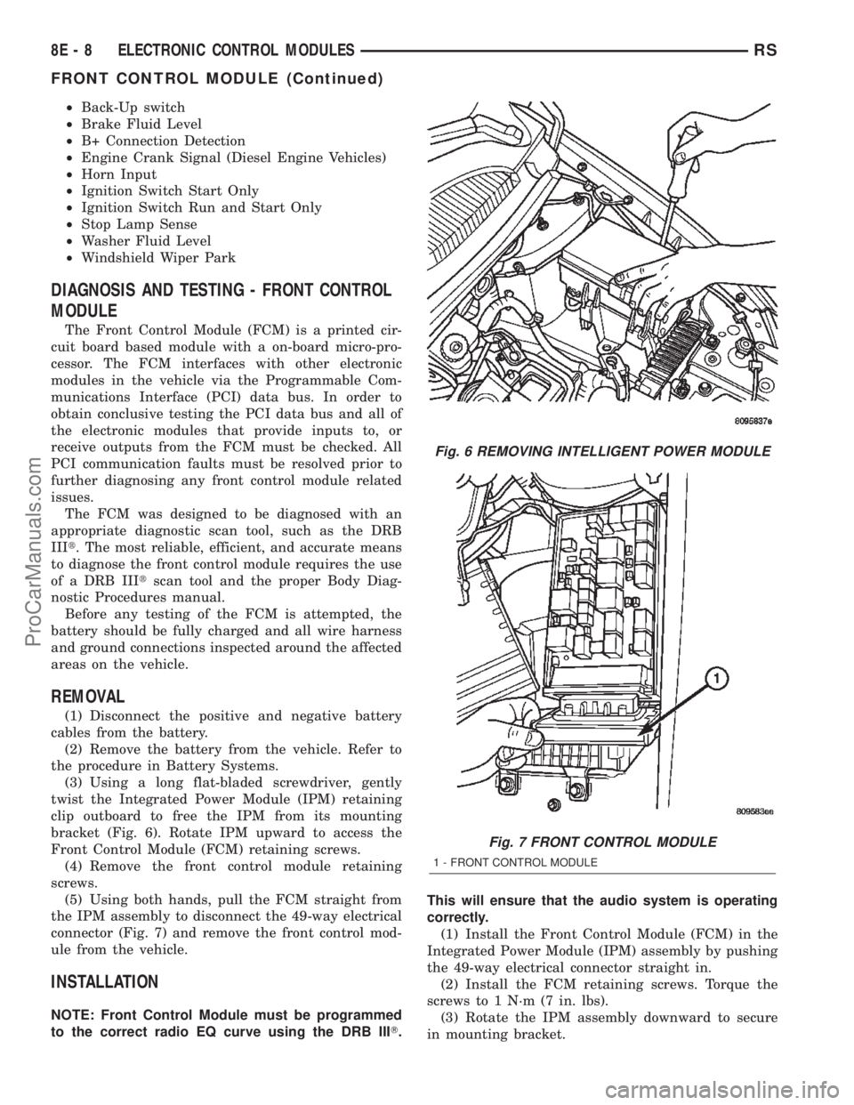
bracket (Fig. 6). Rotate IPM upward to access the
Front Control Module (FCM) retaining screws.
(4) Remove the front control module retaining
screws.
(5) Using both hands, pull the FCM straight from
the IPM assembly to disconnect the 49-way electrical
connector (Fig. 7) and remove the front control mod-
ule from the vehicle.
INSTALLATION
NOTE: Front Control Module must be programmed
to the correct radio EQ curve using the DRB IIIT.This will ensure that the audio system is operating
correctly.
(1) Install the Front Control Module (FCM) in the
Integrated Power Module (IPM) assembly by pushing
the 49-way electrical connector straight in.
(2) Install the FCM retaining screws. Torque the
screws to 1 N´m (7 in. lbs).
(3) Rotate the IPM assembly downward to secure
in mounting bracket.
Fig. 6 REMOVING INTELLIGENT POWER MODULE
Fig. 7 FRONT CONTROL MODULE
1 - FRONT CONTROL MODULE
8E - 8 ELECTRONIC CONTROL MODULESRS
FRONT CONTROL MODULE (Continued)
ProCarManuals.com
Page 348 of 2399
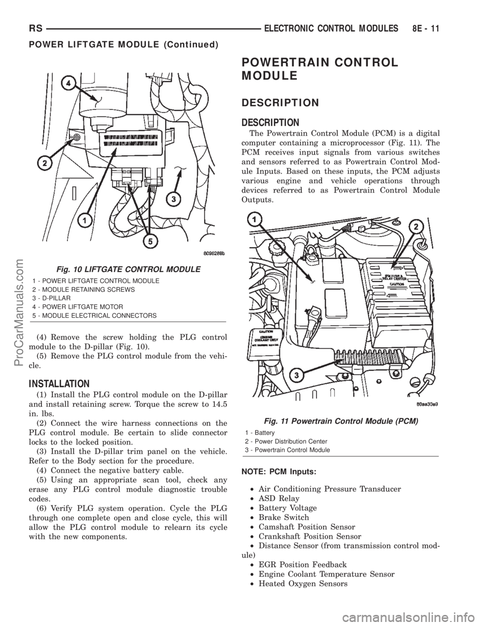
(4) Remove the screw holding the PLG control
module to the D-pillar (Fig. 10).
(5) Remove the PLG control module from the vehi-
cle.
INSTALLATION
(1) Install the PLG control module on the D-pillar
and install retaining screw. Torque the screw to 14.5
in. lbs.
(2) Connect the wire harness connections on the
PLG control module. Be certain to slide connector
locks to the locked position.
(3) Install the D-pillar trim panel on the vehicle.
Refer to the Body section for the procedure.
(4) Connect the negative battery cable.
(5) Using an appropriate scan tool, check any
erase any PLG control module diagnostic trouble
codes.
(6) Verify PLG system operation. Cycle the PLG
through one complete open and close cycle, this will
allow the PLG control module to relearn its cycle
with the new components.
POWERTRAIN CONTROL
MODULE
DESCRIPTION
DESCRIPTION
The Powertrain Control Module (PCM) is a digital
computer containing a microprocessor (Fig. 11). The
PCM receives input signals from various switches
and sensors referred to as Powertrain Control Mod-
ule Inputs. Based on these inputs, the PCM adjusts
various engine and vehicle operations through
devices referred to as Powertrain Control Module
Outputs.
NOTE: PCM Inputs:
²Air Conditioning Pressure Transducer
²ASD Relay
²Battery Voltage
²Brake Switch
²Camshaft Position Sensor
²Crankshaft Position Sensor
²Distance Sensor (from transmission control mod-
ule)
²EGR Position Feedback
²Engine Coolant Temperature Sensor
²Heated Oxygen Sensors
Fig. 10 LIFTGATE CONTROL MODULE
1 - POWER LIFTGATE CONTROL MODULE
2 - MODULE RETAINING SCREWS
3 - D-PILLAR
4 - POWER LIFTGATE MOTOR
5 - MODULE ELECTRICAL CONNECTORS
Fig. 11 Powertrain Control Module (PCM)
1 - Battery
2 - Power Distribution Center
3 - Powertrain Control Module
RSELECTRONIC CONTROL MODULES8E-11
POWER LIFTGATE MODULE (Continued)
ProCarManuals.com
Page 350 of 2399

DIAGNOSTIC TROUBLE CODE
DESCRIPTION
A Diagnostic Trouble Code (DTC) indicates the
PCM has recognized an abnormal condition in the
system.Remember that DTC's are the results of a sys-
tem or circuit failure, but do not directly iden-
tify the failed component or components.
NOTE: For a list of DTC's, refer to the charts in this
section.
(M) Check Engine Lamp (MIL) will illuminate during engine operation if this Diagnostic Trouble Code was recorded.
(G) Generator Lamp Illuminated
GENERIC
SCAN TOOL
CODEDRB SCAN TOOL DISPLAY DESCRIPTION OF DIAGNOSTIC TROUBLE CODE
P0016 Crankshaft/Camshaft Timing
MisalignmentA rationality error has been detected for camshaft position
out of phase with crankshaft
P0030 O2 sensor 1/1 Heater Circuit Shorted condition detected in the oxygen sensor heater
element control feedback sense circuit.
P0031 O2 sensor 1/1 Heater Circuit Shorted condition detected in the oxygen sensor heater
element control feedback sense circuit.
P0036 O2 sensor 1/2 Heater Circuit Shorted condition detected in the oxygen sensor heater
element control feedback sense circuit.
P0037 O2 sensor 1/2 Heater Circuit Shorted condition detected in the oxygen sensor heater
element control feedback sense circuit.
P0038 O2 sensor 1/2 Heater Circuit Shorted condition detected in the oxygen sensor heater
element control feedback sense circuit.
P0043 O2 sensor 1/3 Heater Circuit Shorted condition detected in the oxygen sensor heater
element control feedback sense circuit.
P0044 O2 sensor 1/3 Heater Circuit Shorted condition detected in the oxygen sensor heater
element control feedback sense circuit.
P0050 O2 sensor 2/1 Heater Circuit Shorted condition detected in the oxygen sensor heater
element control feedback sense circuit.
P0051 O2 sensor 2/1 Heater Circuit Shorted condition detected in the oxygen sensor heater
element control feedback sense circuit.
P0052 O2 sensor 2/1 Heater Circuit Shorted condition detected in the oxygen sensor heater
element control feedback sense circuit.
P0056 O2 sensor 2/1 Heater Circuit Shorted condition detected in the oxygen sensor heater
element control feedback sense circuit.
P0057 O2 sensor 2/2 Heater Circuit Shorted condition detected in the oxygen sensor heater
element control feedback sense circuit.
P0058 O2 sensor 2/2 Heater Circuit Shorted condition detected in the oxygen sensor heater
element control feedback sense circuit.
P0068 Manifold Pressure/Throttle Position
CorrelationMAP sensor signal does not correlate to throttle position
sensor signal. Possible vacuum leak.
P0070 Ambient Temp Sensor Stuck A rationality error has been detected in the ambient temp.
sensor test.
P0071 (M) Ambient Temp Sensor Performance Ambient change less than 3É C in 200 Miles
P0072 Ambient Temp Sensor Low Ambient temp. sensor input below the minimum acceptable
voltage
P0073 Ambient Temp Sensor High Ambient temp. sensor input above the maximum acceptable
voltage
RSELECTRONIC CONTROL MODULES8E-13
POWERTRAIN CONTROL MODULE (Continued)
ProCarManuals.com
Page 351 of 2399

(M) Check Engine Lamp (MIL) will illuminate during engine operation if this Diagnostic Trouble Code was recorded.
(G) Generator Lamp Illuminated
GENERIC
SCAN TOOL
CODEDRB SCAN TOOL DISPLAY DESCRIPTION OF DIAGNOSTIC TROUBLE CODE
P0106 (M) Barometric Pressure Out of Range MAP sensor input voltage out of an acceptable range
detected during reading of barometric pressure at key-on.
P0107 (M) Map Sensor Voltage Too Low MAP sensor input below minimum acceptable voltage.
P0108 (M) Map Sensor Voltage Too High MAP sensor input above maximum acceptable voltage.
P0110 Intake Air Temp Sensor Stuck A rationality error has been detected for the intake air temp.
sensor.
P0111 (M) Intake Air Temp Sensor Performance Intake Air change less than 3É C in 200 Miles
P0112 (M) Intake Air Temp Sensor Voltage Low Intake air (charge) temperature sensor input below the
minimum acceptable voltage.
P0113 (M) Intake Air Temp Sensor Voltage High Intake air (charge) temperature sensor input above the
maximum acceptable voltage.
P0116 Engine Coolant Temp Performance A rationality error has been detected in the coolant temp
sensor.
P0117 (M) ECT Sensor Voltage Too Low Engine coolant temperature sensor input below the minimum
acceptable voltage.
P0118 (M) ECT Sensor Voltage Too High Engine coolant temperature sensor input above the
maximum acceptable voltage.
P0121 (M) TPS Voltage Does Not Agree With
MAPTPS signal does not correlate to MAP sensor signal.
P0122 (M) Throttle Position Sensor Voltage Low Throttle position sensor input below the acceptable voltage
range.
P0123 (M) Throttle Position Sensor Voltage High Throttle position sensor input above the maximum
acceptable voltage.
P0125 (M) Engine Coolant Temp Not Reached Time to enter Closed Loop Operation (Fuel Control) is
excessive.
P0128 Thermostat Rationality A rationality error has been detected for the thermostat
P0129 Barometic Pressure Out-of-Range low MAP sensor input voltage out of an acceptable range
detected during reading of barometric pressure.
P0130 1/1 O2 Sensor Heater Relay Circuit An open or shorted condition detected in the ASD or CNG
shutoff relay control ckt.
P0131 (M) 1/1 O2 Sensor Shorted To Ground Oxygen sensor input voltage maintained below normal
operating range.
P0132 (M) 1/1 O2 Sensor Shorted To Voltage Oxygen sensor input voltage maintained above normal
operating range.
P0133 (M) 1/1 O2 Sensor Slow Response Oxygen sensor response slower than minimum required
switching frequency.
P0134 (M) 1/1 O2 Sensor Stays at Center Neither rich or lean condition is detected from the oxygen
sensor input.
P0135 (M) 1/1 O2 Sensor Heater Failure Oxygen sensor heater element malfunction.
P0136 1/2 O2 Sensor Heater Relay Circuit An open or shorted condition detected in the ASD or CNG
shutoff relay control ckt.
P0137 (M) 1/2 O2 Sensor Shorted To Ground Oxygen sensor input voltage maintained below normal
operating range.
8E - 14 ELECTRONIC CONTROL MODULESRS
POWERTRAIN CONTROL MODULE (Continued)
ProCarManuals.com
Page 352 of 2399
(M) Check Engine Lamp (MIL) will illuminate during engine operation if this Diagnostic Trouble Code was recorded.
(G) Generator Lamp Illuminated
GENERIC
SCAN TOOL
CODEDRB SCAN TOOL DISPLAY DESCRIPTION OF DIAGNOSTIC TROUBLE CODE
P0138 (M) 1/2 O2 Sensor Shorted To Voltage Oxygen sensor input voltage maintained above normal
operating range.
P0139 (M) 1/2 O2 Sensor Slow Response Oxygen sensor response not as expected.
P0140 (M) 1/2 O2 Sensor Stays at Center Neither rich or lean condition is detected from the oxygen
sensor.
P0141 (M) 1/2 O2 Sensor Heater Failure Oxygen sensor heater element malfunction.
P0143 1/3 O2 Sensor Shorted To Ground Oxygen sensor input voltage maintained below normal
operating range.
P0144 1/3 O2 Sensor Shorted To Voltage Oxygen sensor input voltage maintained above normal
operating range.
P0145 1/3 O2 Sensor Slow Response Oxygen sensor response slower than minimum required
switching frequency.
P0146 1/3 O2 Sensor Stays at Center Neither rich or lean condition is detected from the oxygen
sensor.
P0147 1/3 O2 Sensor Heater Failure Oxygen sensor heater element malfunction.
P0151 (M) 2/1 O2 Sensor Shorted To Ground Oxygen sensor input voltage maintained below normal
operating range.
P0152 (M) 2/1 O2 Sensor Shorted To Voltage Oxygen sensor input voltage sustained above normal
operating range.
P0153 (M) 2/1 O2 Sensor Slow Response Oxygen sensor response slower than minimum required
switching frequency.
P0154 (M) 2/1 O2 Sensor Stays at Center Neither rich or lean condition is detected from the oxygen
sensor.
P0155 (M) 2/1 O2 Sensor Heater Failure Oxygen sensor heater element malfunction.
P0157 (M) 2/2 O2 Sensor Shorted To Ground Oxygen sensor input voltage maintained below normal
operating range.
P0158 (M) 2/2 O2 Sensor Shorted To Voltage Oxygen sensor input voltage maintained above normal
operating range.
P0159 2/2 O2 Sensor Slow Response Oxygen sensor response slower than minimum required
switching frequency.
P0160 (M) 2/2 O2 Sensor Stays at Center Neither rich or lean condition is detected from the oxygen
sensor.
P0161 (M) 2/2 O2 Sensor Heater Failure Oxygen sensor heater element malfunction.
P0165 Starter Relay Circuit
P0171 (M) 1/1 Fuel System Lean A lean air/fuel mixture has been indicated by an abnormally
rich correction factor.
P0172 (M) 1/1 Fuel System Rich A rich air/fuel mixture has been indicated by an abnormally
lean correction factor.
P0174 (M) 2/1 Fuel System Lean A lean air/fuel mixture has been indicated by an abnormally
rich correction factor.
P0175 (M) 2/1 Fuel System Rich A rich air/fuel mixture has been indicated by an abnormally
lean correction factor.
P0176 Flex Fuel Calibration Signal No calibration voltage present from flex fuel sensor.
RSELECTRONIC CONTROL MODULES8E-15
POWERTRAIN CONTROL MODULE (Continued)
ProCarManuals.com
Page 353 of 2399
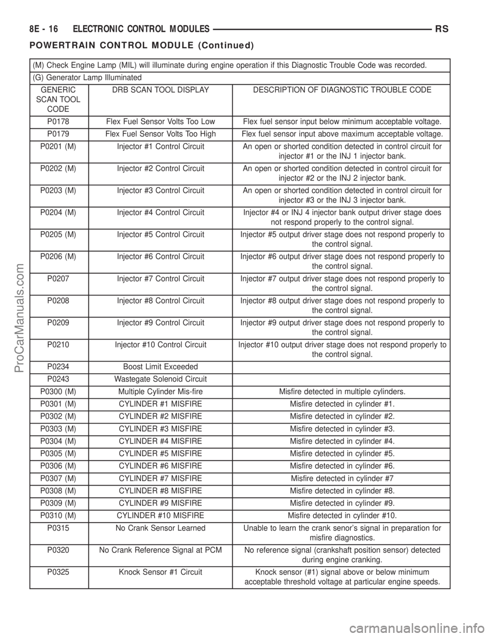
(M) Check Engine Lamp (MIL) will illuminate during engine operation if this Diagnostic Trouble Code was recorded.
(G) Generator Lamp Illuminated
GENERIC
SCAN TOOL
CODEDRB SCAN TOOL DISPLAY DESCRIPTION OF DIAGNOSTIC TROUBLE CODE
P0178 Flex Fuel Sensor Volts Too Low Flex fuel sensor input below minimum acceptable voltage.
P0179 Flex Fuel Sensor Volts Too High Flex fuel sensor input above maximum acceptable voltage.
P0201 (M) Injector #1 Control Circuit An open or shorted condition detected in control circuit for
injector #1 or the INJ 1 injector bank.
P0202 (M) Injector #2 Control Circuit An open or shorted condition detected in control circuit for
injector #2 or the INJ 2 injector bank.
P0203 (M) Injector #3 Control Circuit An open or shorted condition detected in control circuit for
injector #3 or the INJ 3 injector bank.
P0204 (M) Injector #4 Control Circuit Injector #4 or INJ 4 injector bank output driver stage does
not respond properly to the control signal.
P0205 (M) Injector #5 Control Circuit Injector #5 output driver stage does not respond properly to
the control signal.
P0206 (M) Injector #6 Control Circuit Injector #6 output driver stage does not respond properly to
the control signal.
P0207 Injector #7 Control Circuit Injector #7 output driver stage does not respond properly to
the control signal.
P0208 Injector #8 Control Circuit Injector #8 output driver stage does not respond properly to
the control signal.
P0209 Injector #9 Control Circuit Injector #9 output driver stage does not respond properly to
the control signal.
P0210 Injector #10 Control Circuit Injector #10 output driver stage does not respond properly to
the control signal.
P0234 Boost Limit Exceeded
P0243 Wastegate Solenoid Circuit
P0300 (M) Multiple Cylinder Mis-fire Misfire detected in multiple cylinders.
P0301 (M) CYLINDER #1 MISFIRE Misfire detected in cylinder #1.
P0302 (M) CYLINDER #2 MISFIRE Misfire detected in cylinder #2.
P0303 (M) CYLINDER #3 MISFIRE Misfire detected in cylinder #3.
P0304 (M) CYLINDER #4 MISFIRE Misfire detected in cylinder #4.
P0305 (M) CYLINDER #5 MISFIRE Misfire detected in cylinder #5.
P0306 (M) CYLINDER #6 MISFIRE Misfire detected in cylinder #6.
P0307 (M) CYLINDER #7 MISFIRE Misfire detected in cylinder #7
P0308 (M) CYLINDER #8 MISFIRE Misfire detected in cylinder #8.
P0309 (M) CYLINDER #9 MISFIRE Misfire detected in cylinder #9.
P0310 (M) CYLINDER #10 MISFIRE Misfire detected in cylinder #10.
P0315 No Crank Sensor Learned Unable to learn the crank senor's signal in preparation for
misfire diagnostics.
P0320 No Crank Reference Signal at PCM No reference signal (crankshaft position sensor) detected
during engine cranking.
P0325 Knock Sensor #1 Circuit Knock sensor (#1) signal above or below minimum
acceptable threshold voltage at particular engine speeds.
8E - 16 ELECTRONIC CONTROL MODULESRS
POWERTRAIN CONTROL MODULE (Continued)
ProCarManuals.com
Page 354 of 2399

(M) Check Engine Lamp (MIL) will illuminate during engine operation if this Diagnostic Trouble Code was recorded.
(G) Generator Lamp Illuminated
GENERIC
SCAN TOOL
CODEDRB SCAN TOOL DISPLAY DESCRIPTION OF DIAGNOSTIC TROUBLE CODE
P0330 Knock Sensor #2 Circuit Knock sensor (#2) signal above or below minimum
acceptable threshold voltage at particular engine speeds.
P0335 Crankshaft Position Sensor Circuit A rationality error has been detected for loss of crankshaft
position sensor.
P0339 Crankshaft Position Sensor Circuit
IntermittentA rationality error has been detected for intermittent loss of
crankshaft position sensor.
P0340 (M) Camshaft Position Sensor Circuit A rationality error has been detected for loss of camshaft
position sensor.
P0344 Camshaft Position Sensor Circuit
IntermittentA rationality error has been detected for intermittent loss of
camshaft position sensor.
P0350 Ignition Coil Draws Too Much Current A coil (1-5) is drawing too much current.
P0351 (M) Ignition Coil Primary # 1 Circuit Peak primary circuit current not achieved with maximum
dwell time.
P0352 (M) Ignition Coil Primary # 2 Circuit Peak primary circuit current not achieved with maximum
dwell time.
P0353 (M) Ignition Coil Primary # 3 Circuit Peak primary circuit current not achieved with maximum
dwell time.
P0354 (M) Ignition Coil Primary# 4 Circuit Peak primary circuit current not achieved with maximum
dwell time (High Impedance).
P0355 (M) Ignition Coil Primary # 5 Circuit Peak primary circuit current not achieved with maximum
dwell time (High Impedance).
P0356 (M) Ignition Coil Primary # 6 Circuit Peak primary circuit current not achieved with maximum
dwell time (high impedance).
P0357 Ignition Coil Primary # 7 Circuit Peak primary circuit current not achieved with maximum
dwell time (high impedance).
P0358 Ignition Coil Primary # 8 Circuit Peak primary circuit current not achieved with maximum
dwell time (high impedance).
P0400 Diesel EGR System Failure
P0401 (M) EGR System Failure Required change in air/fuel ration not detected during
diagnostic test.
P0403 (M) EGR Solenoid Circuit An open or shorted condition detected in the EGR solenoid
control circuit.
P0404 (M) EGR Position Sensor Rationality EGR position sensor signal does not correlate to EGR duty
cycle.
P0405 (M) EGR Position Sensor Volts Too Low EGR position sensor input below the acceptable voltage
range.
P0406 (M) EGR Position Sensor Volts Too High EGR position sensor input above the acceptable voltage
range.
P0412 Secondary Air Solenoid Circuit An open or shorted condition detected in the secondary air
(air switching/aspirator) solenoid control circuit.
P0420 (M) 1/1 Catalytic Converter Efficiency Catalyst 1/1 efficiency below required level.
P0432 (M) 1/2 Catalytic Converter Efficiency Catalyst 2/1 efficiency below required level.
P0440 General EVAP System Failure General system failure.
RSELECTRONIC CONTROL MODULES8E-17
POWERTRAIN CONTROL MODULE (Continued)
ProCarManuals.com
Page 355 of 2399

(M) Check Engine Lamp (MIL) will illuminate during engine operation if this Diagnostic Trouble Code was recorded.
(G) Generator Lamp Illuminated
GENERIC
SCAN TOOL
CODEDRB SCAN TOOL DISPLAY DESCRIPTION OF DIAGNOSTIC TROUBLE CODE
P0441 (M) Evap Purge Flow Monitor Insufficient or excessive vapor flow detected during
evaporative emission system operation.
P0442 (M) Evap Leak Monitor 0.040 Leak
DetectedA 0.040 leak has been detected in the evaporative system.
P0443 (M) Evap Purge Solenoid Circuit An open or shorted condition detected in the EVAP purge
solenoid control circuit.
P0452 NVLD Pressure Switch Stuck Closed NVLD pressure switch stuck closed.
P0453 NVLD Pressure Switch Stuck Open NVLD pressure switch stuck open.
P0455 (M) Evap Leak Monitor Large Leak
DetectedA large leak has been detected in the evaporative system.
P0456 (M) Evap Leak Monitor 0.020 Leak
DetectedA 0.020 leak has been detected in the evaporative system.
P0460 Fuel Level Unit No Change Over Miles No movement of fuel level sender detected.
P0461 Fuel Level Unit No Changeover Time No level of fuel level sender detected.
P0462 Fuel Level Sending Unit Volts Too Low Fuel level sensor input below acceptable voltage.
P0463 Fuel Level Sending Unit Volts Too
HighFuel level sensor input above acceptable voltage.
P0480 Low Speed Fan Relay Control Circuit An open or shorted condition detected in the low speed rad.
fan relay control circuit.
P0481 High Speed Fan Relay Control Circuit An open or shorted condition detected in the high speed rad.
fan relay control circuit.
P0498 NVLD Canister Vent Valve Solenoid
Circuit LowA shorted low condition detected in NVLD solenoid circuit.
P0499 NVLD Canister Vent Valve Solenoid
Circuit HighA shorted high condition detected in NVLD solenoid circuit.
P0500 (M) No Vehicle Speed Sensor Signal No vehicle speed sensor signal detected during road load
conditions.
P0501 Vehicle Speed Sensor #1 Performance A rationality error has been detected for no vehicle speed
sensor signal detected during road load conditions.
P0505 (M) Idle Air Control Motor Circuits Replace idle air control motor.
P0508 (M) Idle Air Control Motor Circuit Low Idle Air Control Motor Circuit input below acceptable current
P0509 (M) Idle Air Control Motor Circuit High Idle Air Control Motor Circuit input above acceptable current
P0511 Idle Air Control Valve Solenoid Circuit An open or shorted condition detected in the IAC control
circuit.
P0513 Invalid SKIM Key The engine controller has received an invalid key from the
Smart Key Immobilizer Module.
P0516 Battery Temperature Sensor Low Battery Temp. sensor input below minimum acceptable
voltage.
P0517 Battery Temperature Sensor High Battery Temp. sensor input above maximum acceptable
voltage.
P0519 Idle Speed Performance A rationality error has been detected for target RPM not met
during drive idle condition. Possible Vacuum leak or IAC lost
steps.
8E - 18 ELECTRONIC CONTROL MODULESRS
POWERTRAIN CONTROL MODULE (Continued)
ProCarManuals.com
Page 356 of 2399
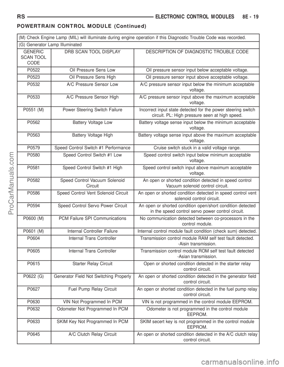
(M) Check Engine Lamp (MIL) will illuminate during engine operation if this Diagnostic Trouble Code was recorded.
(G) Generator Lamp Illuminated
GENERIC
SCAN TOOL
CODEDRB SCAN TOOL DISPLAY DESCRIPTION OF DIAGNOSTIC TROUBLE CODE
P0522 Oil Pressure Sens Low Oil pressure sensor input below acceptable voltage.
P0523 Oil Pressure Sens High Oil pressure sensor input above acceptable voltage.
P0532 A/C Pressure Sensor Low A/C pressure sensor input below the minimum acceptable
voltage.
P0533 A/C Pressure Sensor High A/C pressure sensor input above the maximum acceptable
voltage.
P0551 (M) Power Steering Switch Failure Incorrect input state detected for the power steering switch
circuit. PL: High pressure seen at high speed.
P0562 Battery Voltage Low Battery voltage sense input below the minimum acceptable
voltage.
P0563 Battery Voltage High Battery voltage sense input above the maximum acceptable
voltage.
P0579 Speed Control Switch #1 Performance Cruise switch stuck in a valid voltage range.
P0580 Speed Control Switch #1 Low Speed control switch input below minimum acceptable
voltage.
P0581 Speed Control Switch #1 High Speed control switch input above maximum acceptable
voltage.
P0582 Speed Control Vacuum Solenoid
CircuitAn open or shorted condition detected in speed control
Vacuum solenoid control circuit.
P0586 Speed Control Vent Solenoid Circuit An open or shorted condition detected in speed control vent
solenoid control circuit.
P0594 Speed Control Servo Power Circuit An open or shorted condition open/short condition detected
in the speed control servo power control circuit.
P0600 (M) PCM Failure SPI Communications No communication detected between co-processors in the
control module.
P0601 (M) Internal Controller Failure Internal control module fault condition (check sum) detected.
P0604 Internal Trans Controller Transmission control module RAM self test fault detected.
-Aisin transmission.
P0605 Internal Trans Controller Transmission control module ROM self test fault detected
-Asian transmission.
P0615 Starter Relay Circuit Open or shorted condition detected in the starter relay
control circuit.
P0622 (G) Generator Field Not Switching Properly An open or shorted condition detected in the generator field
control circuit.
P0627 Fuel Pump Relay Circuit An open or shorted condition detected in the fuel pump relay
control circuit.
P0630 VIN Not Programmed In PCM VIN is not programmed in the control module EEPROM.
P0632 Odometer Not Programmed In PCM Odometer is not programmed in the control module
EEPROM.
P0633 SKIM Key Not Programmed In PCM SKIM secert key is not programmed in the control module
EEPROM.
P0645 A/C Clutch Relay Circuit An open or shorted condition detected in the A/C clutch relay
control circuit.
RSELECTRONIC CONTROL MODULES8E-19
POWERTRAIN CONTROL MODULE (Continued)
ProCarManuals.com