transmission removal CHRYSLER TOWN AND COUNTRY 2002 Manual Online
[x] Cancel search | Manufacturer: CHRYSLER, Model Year: 2002, Model line: TOWN AND COUNTRY, Model: CHRYSLER TOWN AND COUNTRY 2002Pages: 2399, PDF Size: 57.96 MB
Page 1854 of 2399
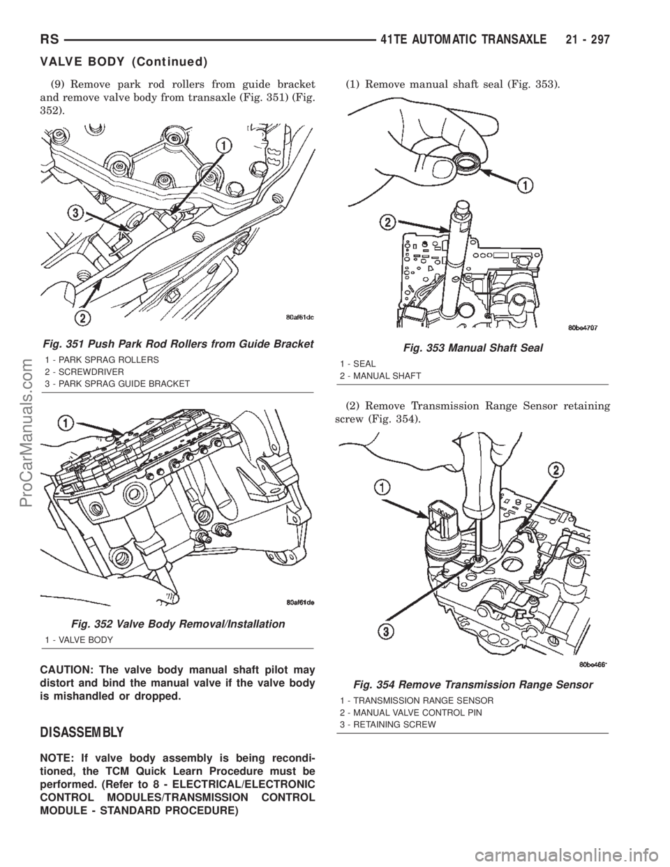
(9) Remove park rod rollers from guide bracket
and remove valve body from transaxle (Fig. 351) (Fig.
352).
CAUTION: The valve body manual shaft pilot may
distort and bind the manual valve if the valve body
is mishandled or dropped.
DISASSEMBLY
NOTE: If valve body assembly is being recondi-
tioned, the TCM Quick Learn Procedure must be
performed. (Refer to 8 - ELECTRICAL/ELECTRONIC
CONTROL MODULES/TRANSMISSION CONTROL
MODULE - STANDARD PROCEDURE)(1) Remove manual shaft seal (Fig. 353).
(2) Remove Transmission Range Sensor retaining
screw (Fig. 354).
Fig. 351 Push Park Rod Rollers from Guide Bracket
1 - PARK SPRAG ROLLERS
2 - SCREWDRIVER
3 - PARK SPRAG GUIDE BRACKET
Fig. 352 Valve Body Removal/Installation
1 - VALVE BODY
Fig. 353 Manual Shaft Seal
1 - SEAL
2 - MANUAL SHAFT
Fig. 354 Remove Transmission Range Sensor
1 - TRANSMISSION RANGE SENSOR
2 - MANUAL VALVE CONTROL PIN
3 - RETAINING SCREW
RS41TE AUTOMATIC TRANSAXLE21 - 297
VALVE BODY (Continued)
ProCarManuals.com
Page 1863 of 2399
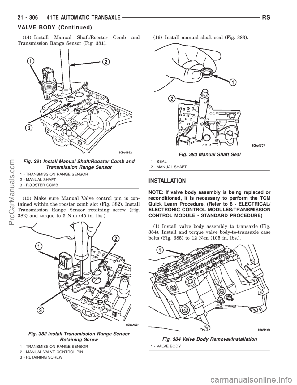
(14) Install Manual Shaft/Rooster Comb and
Transmission Range Sensor (Fig. 381).
(15) Make sure Manual Valve control pin is con-
tained within the rooster comb slot (Fig. 382). Install
Transmission Range Sensor retaining screw (Fig.
382) and torque to 5 N´m (45 in. lbs.).(16) Install manual shaft seal (Fig. 383).
INSTALLATION
NOTE: If valve body assembly is being replaced or
reconditioned, it is necessary to perform the TCM
Quick Learn Procedure. (Refer to 8 - ELECTRICAL/
ELECTRONIC CONTROL MODULES/TRANSMISSION
CONTROL MODULE - STANDARD PROCEDURE)
(1) Install valve body assembly to transaxle (Fig.
384). Install and torque valve body-to-transaxle case
bolts (Fig. 385) to 12 N´m (105 in. lbs.).
Fig. 381 Install Manual Shaft/Rooster Comb and
Transmission Range Sensor
1 - TRANSMISSION RANGE SENSOR
2 - MANUAL SHAFT
3 - ROOSTER COMB
Fig. 382 Install Transmission Range Sensor
Retaining Screw
1 - TRANSMISSION RANGE SENSOR
2 - MANUAL VALVE CONTROL PIN
3 - RETAINING SCREW
Fig. 383 Manual Shaft Seal
1 - SEAL
2 - MANUAL SHAFT
Fig. 384 Valve Body Removal/Installation
1 - VALVE BODY
21 - 306 41TE AUTOMATIC TRANSAXLERS
VALVE BODY (Continued)
ProCarManuals.com
Page 1876 of 2399
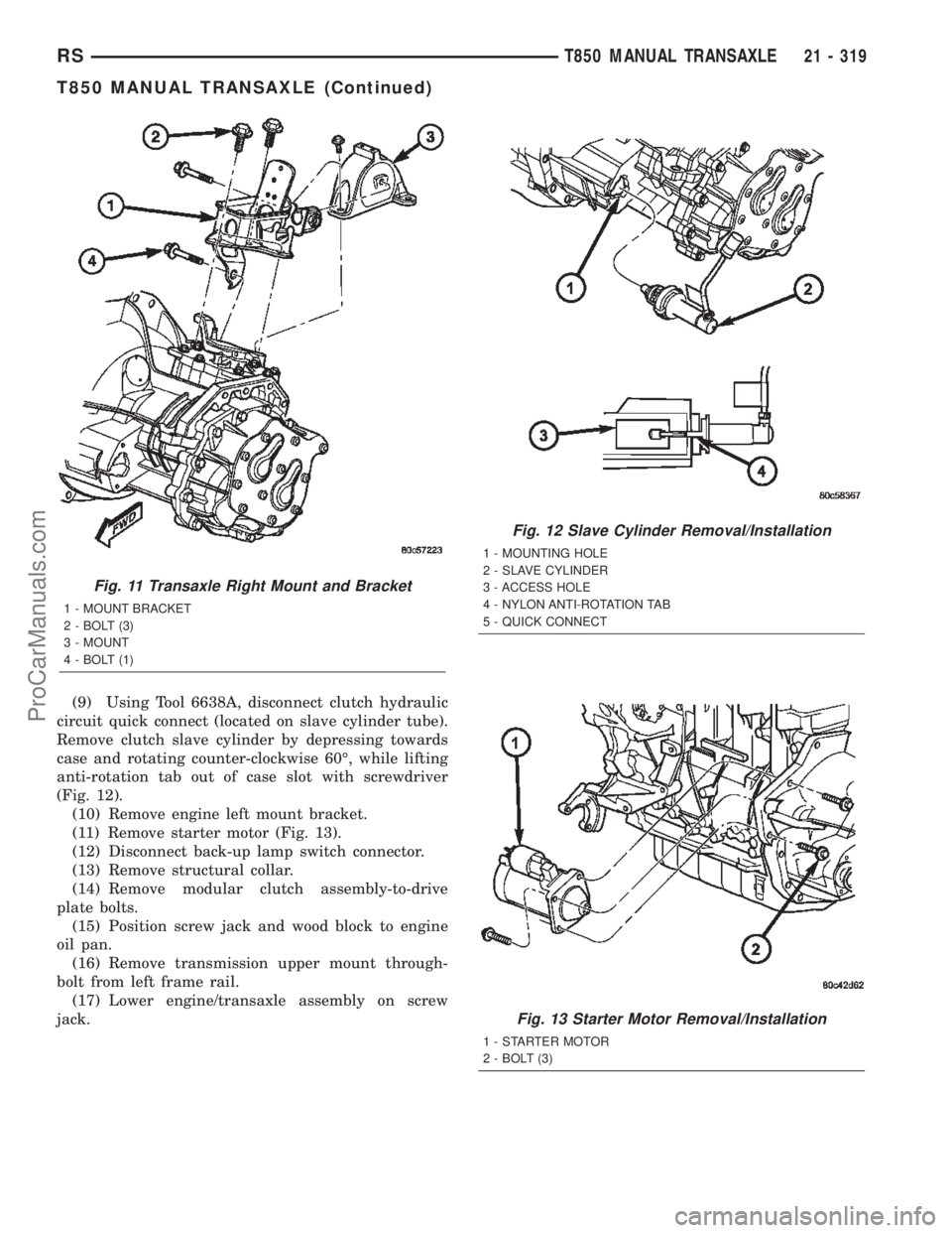
(9) Using Tool 6638A, disconnect clutch hydraulic
circuit quick connect (located on slave cylinder tube).
Remove clutch slave cylinder by depressing towards
case and rotating counter-clockwise 60É, while lifting
anti-rotation tab out of case slot with screwdriver
(Fig. 12).
(10) Remove engine left mount bracket.
(11) Remove starter motor (Fig. 13).
(12) Disconnect back-up lamp switch connector.
(13) Remove structural collar.
(14) Remove modular clutch assembly-to-drive
plate bolts.
(15) Position screw jack and wood block to engine
oil pan.
(16) Remove transmission upper mount through-
bolt from left frame rail.
(17) Lower engine/transaxle assembly on screw
jack.
Fig. 11 Transaxle Right Mount and Bracket
1 - MOUNT BRACKET
2 - BOLT (3)
3 - MOUNT
4 - BOLT (1)
Fig. 12 Slave Cylinder Removal/Installation
1 - MOUNTING HOLE
2 - SLAVE CYLINDER
3 - ACCESS HOLE
4 - NYLON ANTI-ROTATION TAB
5 - QUICK CONNECT
Fig. 13 Starter Motor Removal/Installation
1 - STARTER MOTOR
2 - BOLT (3)
RST850 MANUAL TRANSAXLE21 - 319
T850 MANUAL TRANSAXLE (Continued)
ProCarManuals.com
Page 1877 of 2399
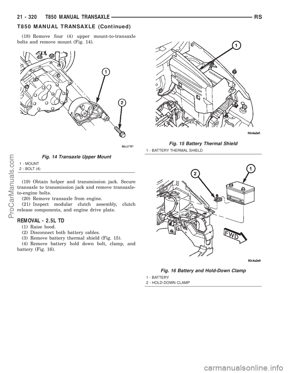
(18) Remove four (4) upper mount-to-transaxle
bolts and remove mount (Fig. 14).
(19) Obtain helper and transmission jack. Secure
transaxle to transmission jack and remove transaxle-
to-engine bolts.
(20) Remove transaxle from engine.
(21) Inspect modular clutch assembly, clutch
release components, and engine drive plate.
REMOVAL - 2.5L TD
(1) Raise hood.
(2) Disconnect both battery cables.
(3) Remove battery thermal shield (Fig. 15).
(4) Remove battery hold down bolt, clamp, and
battery (Fig. 16).
Fig. 14 Transaxle Upper Mount
1 - MOUNT
2 - BOLT (4)
Fig. 15 Battery Thermal Shield
1 - BATTERY THERMAL SHIELD
Fig. 16 Battery and Hold-Down Clamp
1 - BATTERY
2 - HOLD-DOWN CLAMP
21 - 320 T850 MANUAL TRANSAXLERS
T850 MANUAL TRANSAXLE (Continued)
ProCarManuals.com
Page 1879 of 2399
(11) Raise vehicle on hoist.
(12) Remove front wheel/tires and halfshafts.
(13) Remove underbody splash shield.
(14) Drain transaxle fluid into suitable container.
(15) Remove front harness retainer and secure
harness out of way.
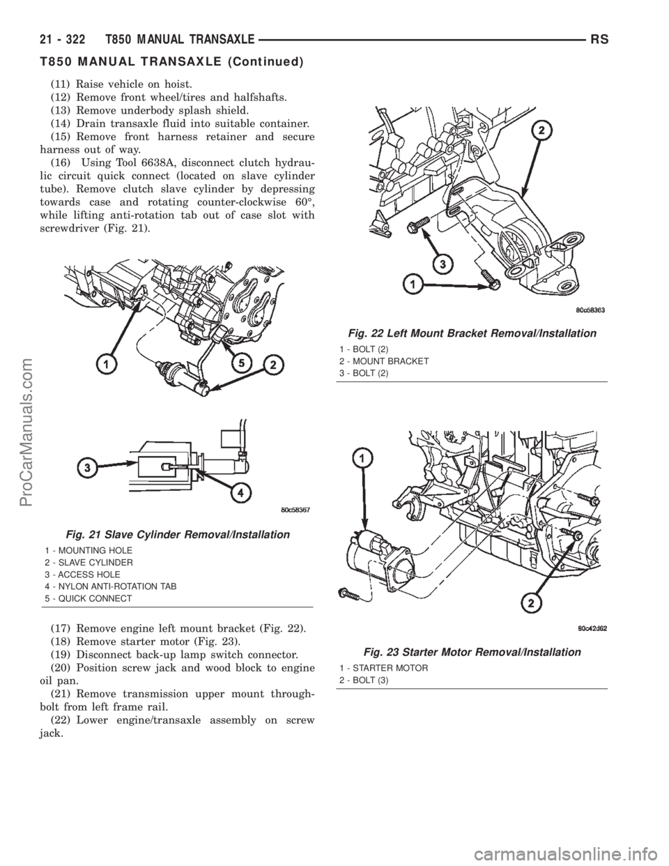
(16) Using Tool 6638A, disconnect clutch hydrau-
lic circuit quick connect (located on slave cylinder
tube). Remove clutch slave cylinder by depressing
towards case and rotating counter-clockwise 60É,
while lifting anti-rotation tab out of case slot with
screwdriver (Fig. 21).
(17) Remove engine left mount bracket (Fig. 22).
(18) Remove starter motor (Fig. 23).
(19) Disconnect back-up lamp switch connector.
(20) Position screw jack and wood block to engine
oil pan.
(21) Remove transmission upper mount through-
bolt from left frame rail.
(22) Lower engine/transaxle assembly on screw
jack.
Fig. 21 Slave Cylinder Removal/Installation
1 - MOUNTING HOLE
2 - SLAVE CYLINDER
3 - ACCESS HOLE
4 - NYLON ANTI-ROTATION TAB
5 - QUICK CONNECT
Fig. 22 Left Mount Bracket Removal/Installation
1 - BOLT (2)
2 - MOUNT BRACKET
3 - BOLT (2)
Fig. 23 Starter Motor Removal/Installation
1 - STARTER MOTOR
2 - BOLT (3)
21 - 322 T850 MANUAL TRANSAXLERS
T850 MANUAL TRANSAXLE (Continued)
ProCarManuals.com
Page 1880 of 2399
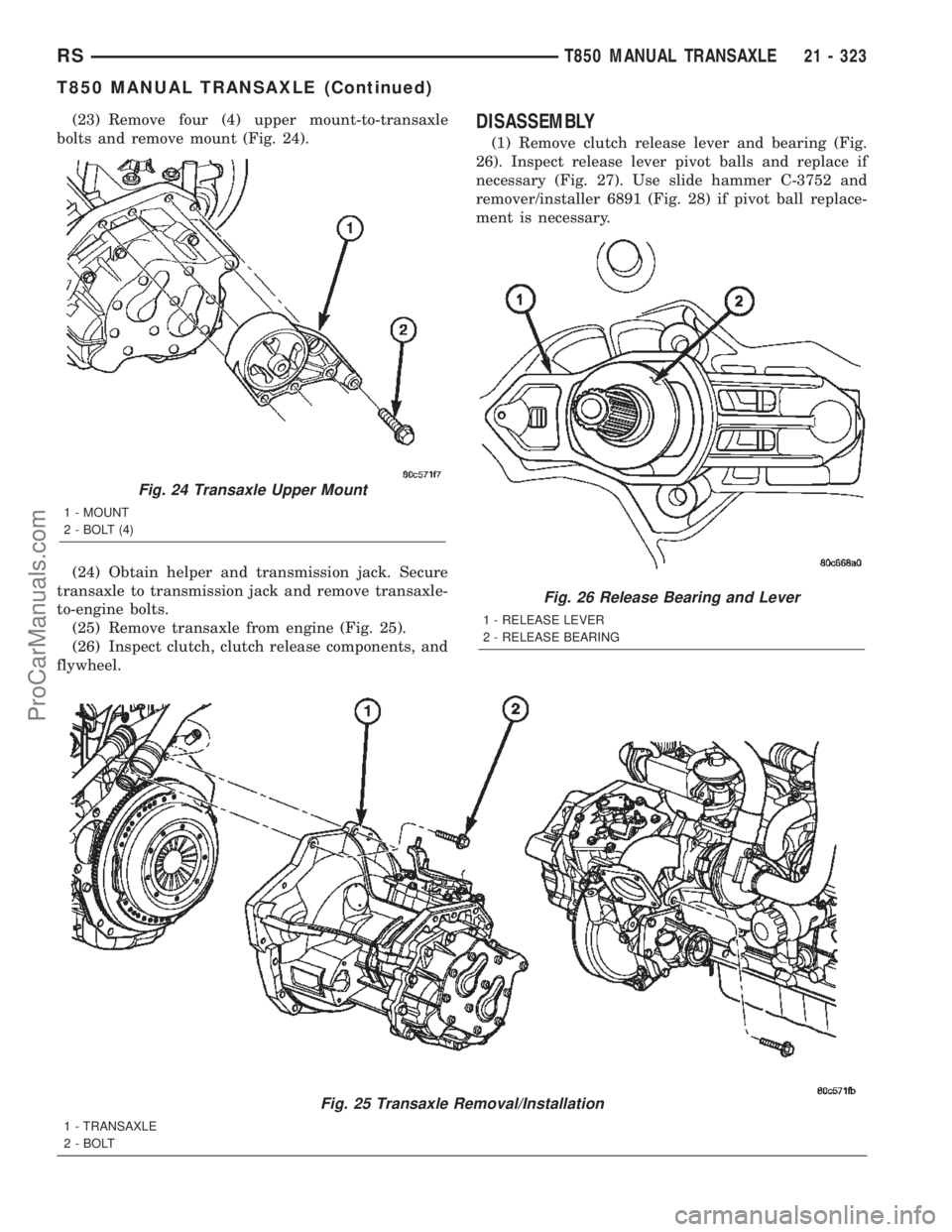
(23) Remove four (4) upper mount-to-transaxle
bolts and remove mount (Fig. 24).
(24) Obtain helper and transmission jack. Secure
transaxle to transmission jack and remove transaxle-
to-engine bolts.
(25) Remove transaxle from engine (Fig. 25).
(26) Inspect clutch, clutch release components, and
flywheel.DISASSEMBLY
(1) Remove clutch release lever and bearing (Fig.
26). Inspect release lever pivot balls and replace if
necessary (Fig. 27). Use slide hammer C-3752 and
remover/installer 6891 (Fig. 28) if pivot ball replace-
ment is necessary.
Fig. 25 Transaxle Removal/Installation
1 - TRANSAXLE
2 - BOLT
Fig. 24 Transaxle Upper Mount
1 - MOUNT
2 - BOLT (4)
Fig. 26 Release Bearing and Lever
1 - RELEASE LEVER
2 - RELEASE BEARING
RST850 MANUAL TRANSAXLE21 - 323
T850 MANUAL TRANSAXLE (Continued)
ProCarManuals.com
Page 1884 of 2399
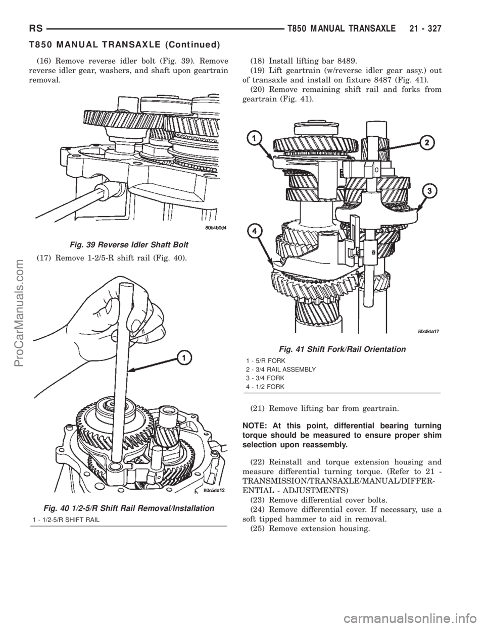
(16) Remove reverse idler bolt (Fig. 39). Remove
reverse idler gear, washers, and shaft upon geartrain
removal.
(17) Remove 1-2/5-R shift rail (Fig. 40).(18) Install lifting bar 8489.
(19) Lift geartrain (w/reverse idler gear assy.) out
of transaxle and install on fixture 8487 (Fig. 41).
(20) Remove remaining shift rail and forks from
geartrain (Fig. 41).
(21) Remove lifting bar from geartrain.
NOTE: At this point, differential bearing turning
torque should be measured to ensure proper shim
selection upon reassembly.
(22) Reinstall and torque extension housing and
measure differential turning torque. (Refer to 21 -
TRANSMISSION/TRANSAXLE/MANUAL/DIFFER-
ENTIAL - ADJUSTMENTS)
(23) Remove differential cover bolts.
(24) Remove differential cover. If necessary, use a
soft tipped hammer to aid in removal.
(25) Remove extension housing.
Fig. 39 Reverse Idler Shaft Bolt
Fig. 40 1/2-5/R Shift Rail Removal/Installation
1 - 1/2-5/R SHIFT RAIL
Fig. 41 Shift Fork/Rail Orientation
1 - 5/R FORK
2 - 3/4 RAIL ASSEMBLY
3 - 3/4 FORK
4 - 1/2 FORK
RST850 MANUAL TRANSAXLE21 - 327
T850 MANUAL TRANSAXLE (Continued)
ProCarManuals.com
Page 1886 of 2399
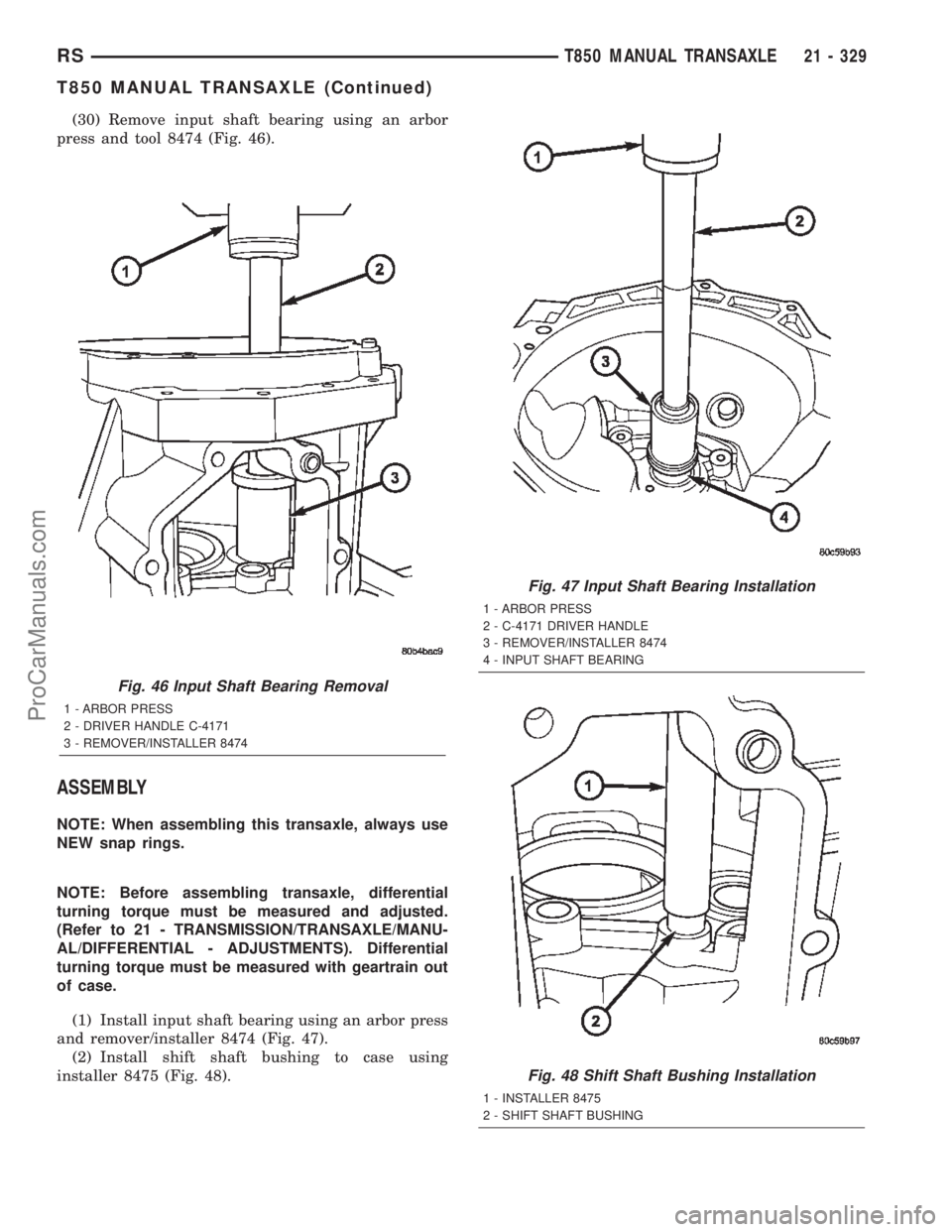
(30) Remove input shaft bearing using an arbor
press and tool 8474 (Fig. 46).
ASSEMBLY
NOTE: When assembling this transaxle, always use
NEW snap rings.
NOTE: Before assembling transaxle, differential
turning torque must be measured and adjusted.
(Refer to 21 - TRANSMISSION/TRANSAXLE/MANU-
AL/DIFFERENTIAL - ADJUSTMENTS). Differential
turning torque must be measured with geartrain out
of case.
(1) Install input shaft bearing using an arbor press
and remover/installer 8474 (Fig. 47).
(2) Install shift shaft bushing to case using
installer 8475 (Fig. 48).
Fig. 46 Input Shaft Bearing Removal
1 - ARBOR PRESS
2 - DRIVER HANDLE C-4171
3 - REMOVER/INSTALLER 8474
Fig. 47 Input Shaft Bearing Installation
1 - ARBOR PRESS
2 - C-4171 DRIVER HANDLE
3 - REMOVER/INSTALLER 8474
4 - INPUT SHAFT BEARING
Fig. 48 Shift Shaft Bushing Installation
1 - INSTALLER 8475
2 - SHIFT SHAFT BUSHING
RST850 MANUAL TRANSAXLE21 - 329
T850 MANUAL TRANSAXLE (Continued)
ProCarManuals.com
Page 1905 of 2399
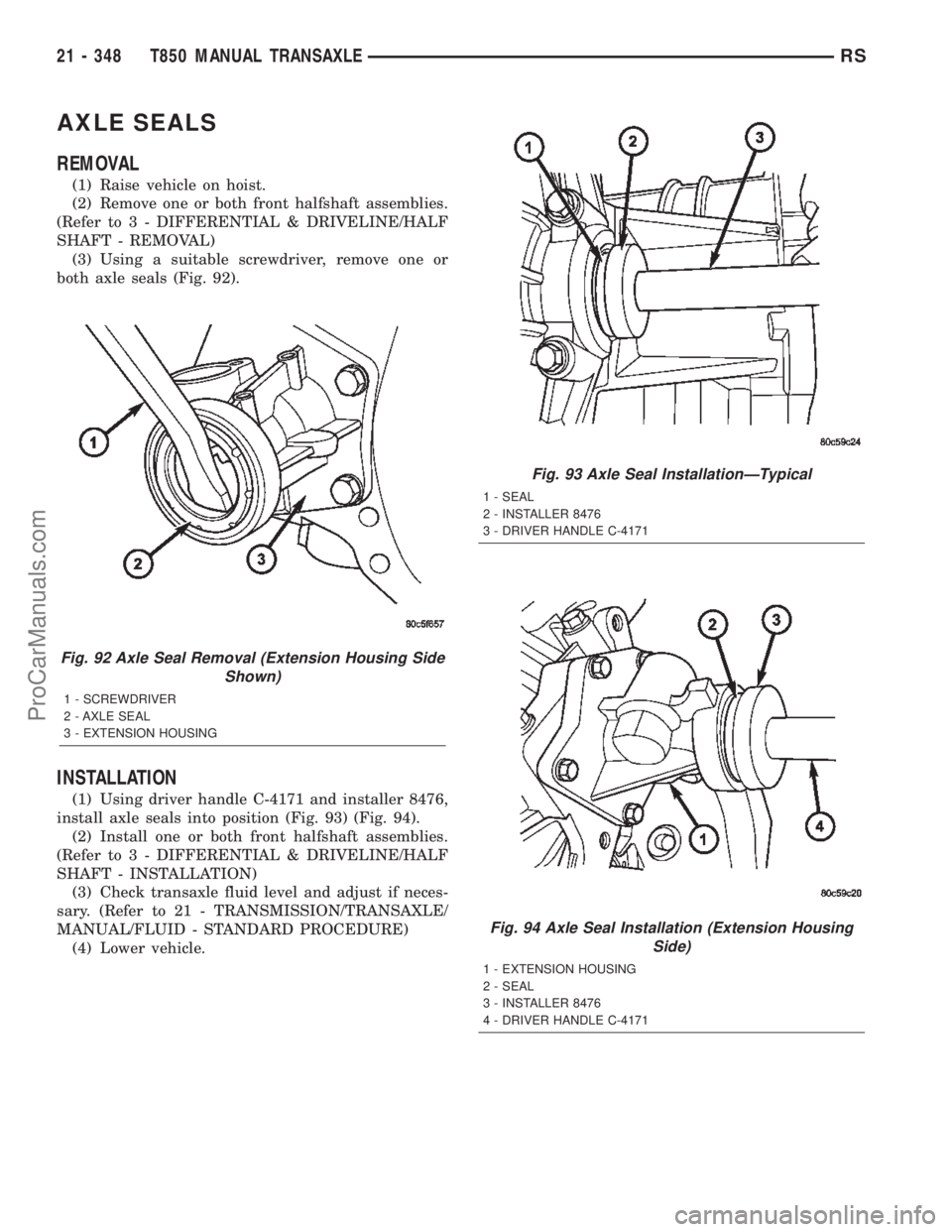
AXLE SEALS
REMOVAL
(1) Raise vehicle on hoist.
(2) Remove one or both front halfshaft assemblies.
(Refer to 3 - DIFFERENTIAL & DRIVELINE/HALF
SHAFT - REMOVAL)
(3) Using a suitable screwdriver, remove one or
both axle seals (Fig. 92).
INSTALLATION
(1) Using driver handle C-4171 and installer 8476,
install axle seals into position (Fig. 93) (Fig. 94).
(2) Install one or both front halfshaft assemblies.
(Refer to 3 - DIFFERENTIAL & DRIVELINE/HALF
SHAFT - INSTALLATION)
(3) Check transaxle fluid level and adjust if neces-
sary. (Refer to 21 - TRANSMISSION/TRANSAXLE/
MANUAL/FLUID - STANDARD PROCEDURE)
(4) Lower vehicle.
Fig. 92 Axle Seal Removal (Extension Housing Side
Shown)
1 - SCREWDRIVER
2 - AXLE SEAL
3 - EXTENSION HOUSING
Fig. 93 Axle Seal InstallationÐTypical
1 - SEAL
2 - INSTALLER 8476
3 - DRIVER HANDLE C-4171
Fig. 94 Axle Seal Installation (Extension Housing
Side)
1 - EXTENSION HOUSING
2 - SEAL
3 - INSTALLER 8476
4 - DRIVER HANDLE C-4171
21 - 348 T850 MANUAL TRANSAXLERS
ProCarManuals.com
Page 1916 of 2399
STANDARD PROCEDURE - FLUID DRAIN AND
FILL
NOTE: For proper fluid change intervals, (Refer to
LUBRICATION & MAINTENANCE/MAINTENANCE
SCHEDULES - DESCRIPTION)
The fluid required in this transaxle is Mopart
ATF+4 (Automatic Transmission FluidÐType 9602).
Use of substitute fluids may result in improper
transaxle operation and/or failure.
FLUID DRAIN
(1) Raise vehicle on hoist.
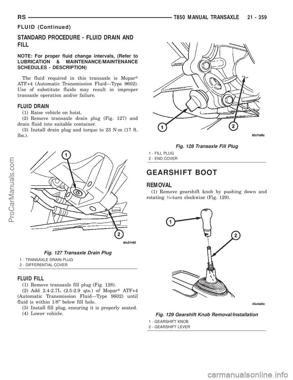
(2) Remove transaxle drain plug (Fig. 127) and
drain fluid into suitable container.
(3) Install drain plug and torque to 23 N´m (17 ft.
lbs.).
FLUID FILL
(1) Remove transaxle fill plug (Fig. 128).
(2) Add 2.4-2.7L (2.5-2.9 qts.) of MopartATF+4
(Automatic Transmission FluidÐType 9602) until
fluid is within 1/8º below fill hole.
(3) Install fill plug, ensuring it is properly seated.
(4) Lower vehicle.
GEARSHIFT BOOT
REMOVAL
(1) Remove gearshift knob by pushing down and
rotating1¤4-turn clockwise (Fig. 129).
Fig. 127 Transaxle Drain Plug
1 - TRANSAXLE DRAIN PLUG
2 - DIFFERENTIAL COVER
Fig. 128 Transaxle Fill Plug
1 - FILL PLUG
2 - END COVER
Fig. 129 Gearshift Knob Removal/Installation
1 - GEARSHIFT KNOB
2 - GEARSHIFT LEVER
RST850 MANUAL TRANSAXLE21 - 359
FLUID (Continued)
ProCarManuals.com