remove CHRYSLER TOWN AND COUNTRY 2005 4.G Service Manual
[x] Cancel search | Manufacturer: CHRYSLER, Model Year: 2005, Model line: TOWN AND COUNTRY, Model: CHRYSLER TOWN AND COUNTRY 2005 4.GPages: 472
Page 300 of 472
WARNING!
It is dangerous to shift the selector lever out of“P”or
“N”if the engine speed is higher than idle speed. If
your foot is not firmly on the brake pedal, the
vehicle could accelerate quickly forward or in re-
verse. You could lose control of the vehicle and hit
someone or something. Only shift into gear when
the engine is idling normally and when your right
foot is firmly on the brake pedal.
Brake/Transmission Interlock System
This system prevents you from moving the gear shift out
of Park and into any gear unless the brake pedal is
pressed. This system is active only while the ignition
switch is in the ON position. Always depress thebrake
pedal first,before moving the gear selector out of PARK.
Automatic Transmission Ignition Interlock System
This system prevents the key from being removed unless
the shift lever is in PARK. It also prevents shifting out of
PARK unless the key is in the OFF or ON positions.
NOTE:If a malfunction occurs, the system will trap the
key in the ignition cylinder to warn you that this safety
feature is inoperable. The engine can be started and
stopped but the key cannot be removed until you obtain
service.
Four Speed Automatic Transmission
The electronically controlled transmission provides a
precise shift schedule. The transmission electronics are
self-calibrating; therefore, the first few shifts on a new
vehicle, may be somewhat abrupt. This is a normal
condition, and precision shifts will develop within a few
hundred miles.
300 STARTING AND OPERATING
Page 330 of 472
TIRE CHAINS
Use only compact chains, or other traction aids that meet
SAE type“Class S”specifications. Chains must be the
proper size for the vehicle, as recommended by the chain
manufacturer.
NOTE:Do not use tire chains on a compact spare tire.CAUTION!
To avoid damage to your vehicle or tires, observe the following
precautions:
•Because of restricted chain clearance between tires and other sus-
pension components, it is important that only chains in good
condition are used. Broken chains can cause serious damage. Stop
the vehicle immediately if noise occurs that could indicate chain
breakage. Remove the damaged parts of the chain before further
use.
•Install chains on the front wheels as tightly as possible and then
retighten after driving about1⁄2mile (0.8 km).
•Do not exceed 45 mph (70 km/h).
•Drive cautiously and avoid severe turns and large bumps, especially
with a loaded vehicle.
•Do not use on rear wheels of All Wheel Drive (AWD) vehicles.
•Do not drive for prolonged period on dry pavement.
•Observe the tire chain manufacturer’s instructions on the method of
installation, operating speed, and conditions for use. Always use the
lower suggested operating speed of the chain manufacturer if
different than the speed recommended by the manufacture.
330 STARTING AND OPERATING
Page 338 of 472
WARNING!
•Never have any smoking materials lit in or near
the vehicle when the gas cap is removed or the
tank filled.
•Never add fuel to the vehicle when the engine is
running.
•A fire may result if gasoline is pumped into a
portable container that is inside of a vehicle. You
could be burned. Always place gas containers on
the ground while filling.
VEHICLE LOADING
The load carrying capacity of your vehicle is shown in the
charts that follow. This information should be used for
passenger and luggage loading as indicated.
If seats are removed for carrying cargo, do not exceed the
specified GVWR and GAWR.
Vehicle Certification Label
Your vehicle has a certification label attached to the
driver’s door pillar.
The label contains the following information:
•Name of manufacturer
•Month and year of manufacture
•Gross Vehicle Weight Rating (GVWR)
•Gross Axle Weight Rating (GAWR) front
•Gross Axle Weight Rating (GAWR) rear
338 STARTING AND OPERATING
Page 347 of 472
IF YOUR ENGINE OVERHEATS
In any of the following situations, you can reduce the
potential for overheating by taking the appropriate ac-
tion.
•On the highways—Slow down.
•In city traffic—While stopped, put transmission in
neutral, but do not increase engine idle speed.
NOTE:There are steps that you can take to slow down
an impending overheat condition. If your air conditioner
is on, turn it off. The air conditioning system adds heat to
the engine cooling system and turning off the A/C
removes this heat. You can also turn the Temperature
control to maximum heat, the Mode control to floor, and
the fan control to High. This allows the heater core to act
as a supplement to the radiator and aids in removing heat
from the engine cooling system.
CAUTION!
Driving with a hot cooling system could damage
your vehicle. If temperature gauge reads“H”, pull
over and stop the vehicle. Idle the vehicle with the
air conditioner turned off until the pointer drops
back into the normal range. If the pointer remains on
the“H”, turn the engine off immediately, and call for
service.
WHAT TO DO IN EMERGENCIES 347
6
Page 350 of 472
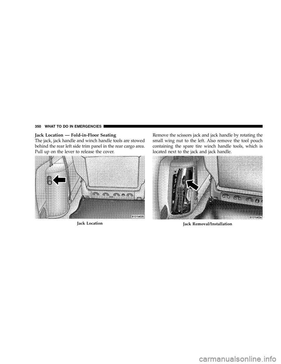
Jack Location—Fold-in-Floor Seating
The jack, jack handle and winch handle tools are stowed
behind the rear left side trim panel in the rear cargo area.
Pull up on the lever to release the cover.Remove the scissors jack and jack handle by rotating the
small wing nut to the left. Also remove the tool pouch
containing the spare tire winch handle tools, which is
located next to the jack and jack handle.
Jack LocationJack Removal/Installation
350 WHAT TO DO IN EMERGENCIES
Page 351 of 472
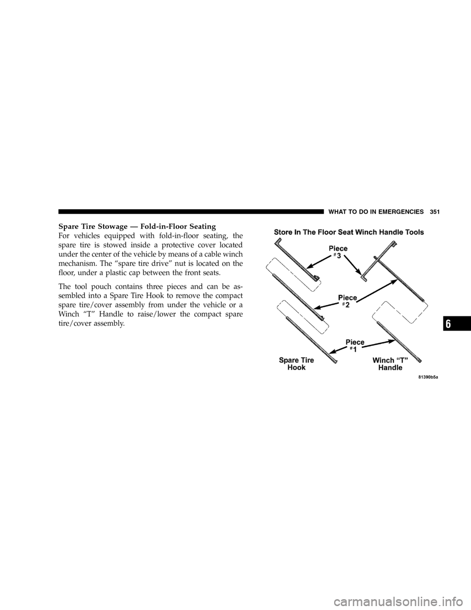
Spare Tire Stowage—Fold-in-Floor Seating
For vehicles equipped with fold-in-floor seating, the
spare tire is stowed inside a protective cover located
under the center of the vehicle by means of a cable winch
mechanism. The“spare tire drive”nut is located on the
floor, under a plastic cap between the front seats.
The tool pouch contains three pieces and can be as-
sembled into a Spare Tire Hook to remove the compact
spare tire/cover assembly from under the vehicle or a
Winch“T”Handle to raise/lower the compact spare
tire/cover assembly.
WHAT TO DO IN EMERGENCIES 351
6
Page 352 of 472
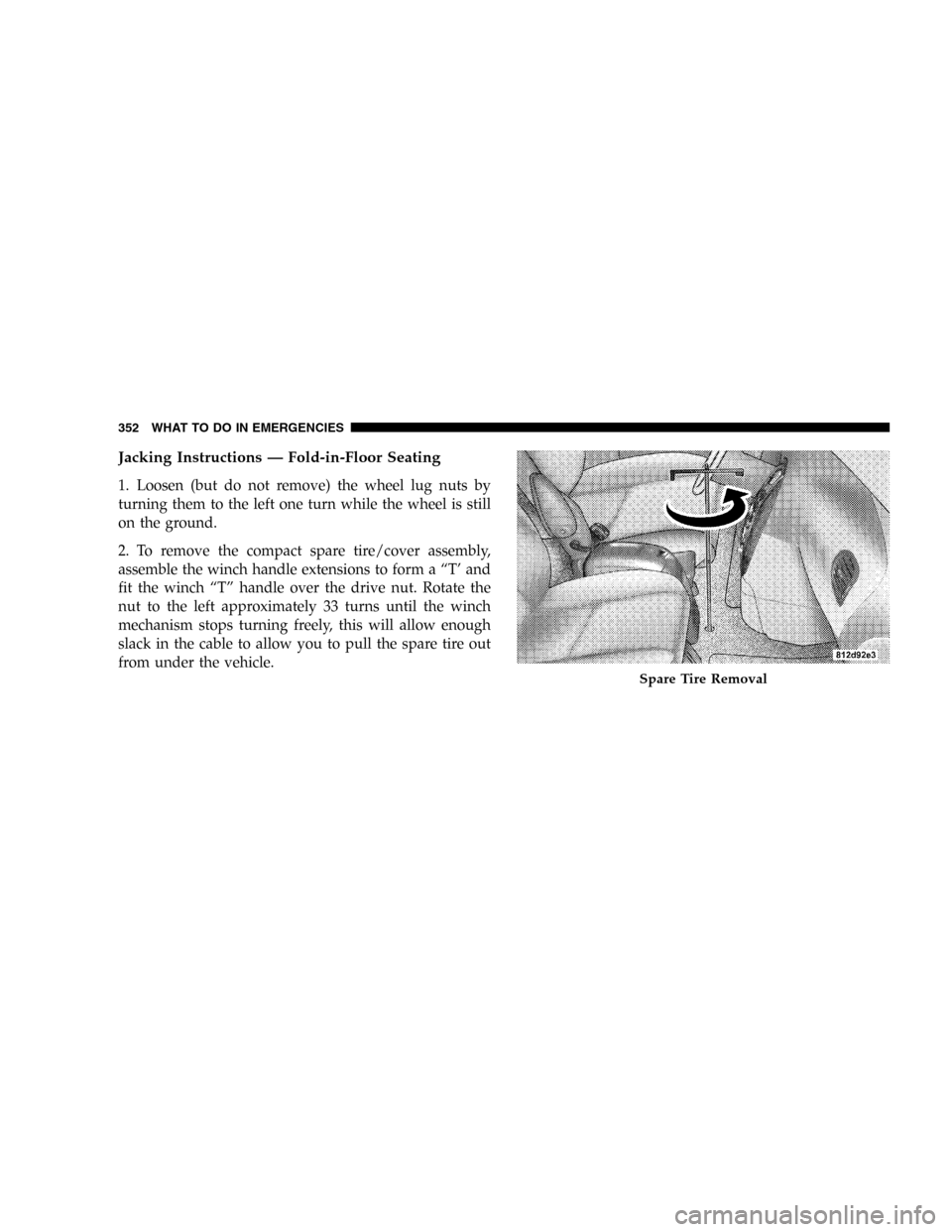
Jacking Instructions—Fold-in-Floor Seating
1. Loosen (but do not remove) the wheel lug nuts by
turning them to the left one turn while the wheel is still
on the ground.
2. To remove the compact spare tire/cover assembly,
assemble the winch handle extensions to form a“T’and
fit the winch“T”handle over the drive nut. Rotate the
nut to the left approximately 33 turns until the winch
mechanism stops turning freely, this will allow enough
slack in the cable to allow you to pull the spare tire out
from under the vehicle.
Spare Tire Removal
352 WHAT TO DO IN EMERGENCIES
Page 354 of 472
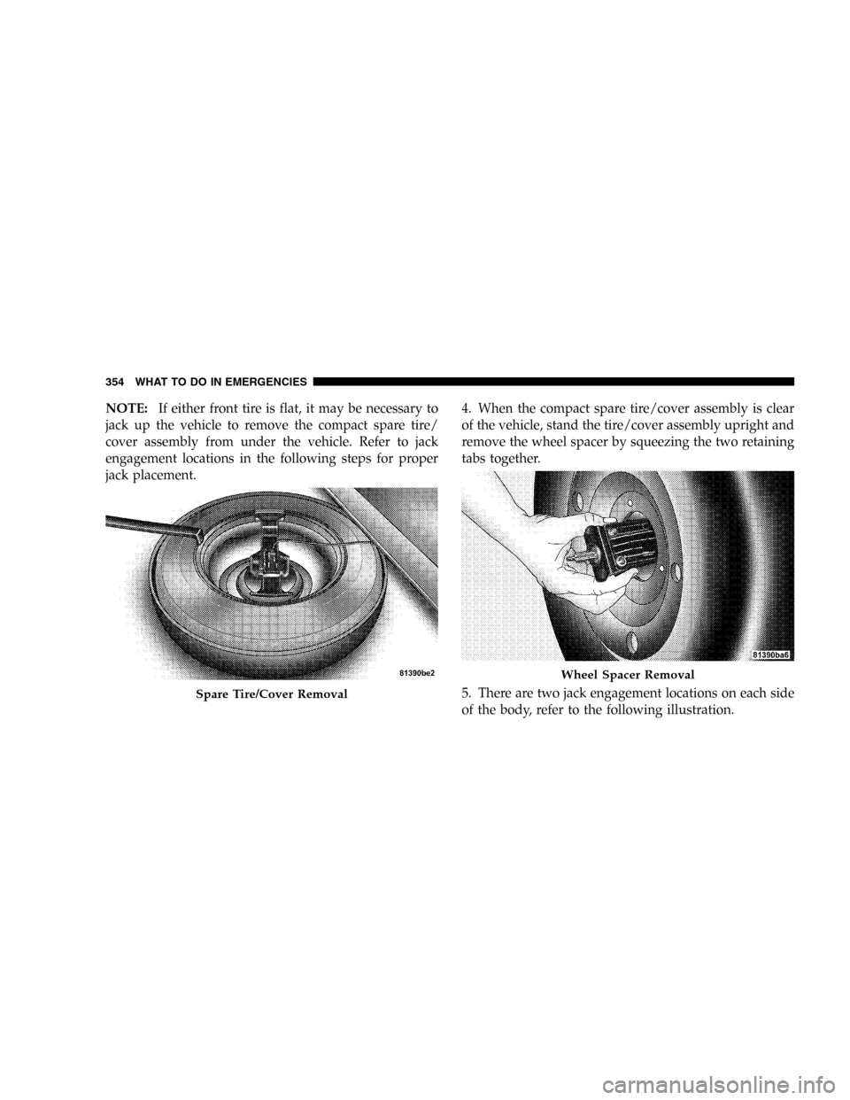
NOTE:If either front tire is flat, it may be necessary to
jack up the vehicle to remove the compact spare tire/
cover assembly from under the vehicle. Refer to jack
engagement locations in the following steps for proper
jack placement.4. When the compact spare tire/cover assembly is clear
of the vehicle, stand the tire/cover assembly upright and
remove the wheel spacer by squeezing the two retaining
tabs together.
5. There are two jack engagement locations on each side
of the body, refer to the following illustration.
Spare Tire/Cover Removal
Wheel Spacer Removal
354 WHAT TO DO IN EMERGENCIES
Page 356 of 472
6. These locations are on the sill flange of the body and
consist of a pair of downstanding tabs. The jack is to be
located, engaging the flange, between the pair of tabs
closest to the wheel to be changed. Place the wrench on
the jack screw and turn to the right until the jack head is
properly engaged in the described location.Do not raise
the vehicle until you are sure the jack is securely
engaged.
7. Raise the vehicle by turning the jack screw to the right,
using the swivel wrench. Raise the vehicle only until the
tire just clears the surface and enough clearance is
obtained to install the spare tire. Minimum tire lift
provides maximum stability.WARNING!
Raising the vehicle higher than necessary can make
the vehicle less stable. It could slip off the jack and
hurt someone near it. Raise the vehicle only enough
to remove the tire.
8. Remove the wheel lug nuts, for vehicles with wheel
covers, remove the cover from the wheel by hand. Do not
pry the wheel cover off. Then pull the wheel off the hub.
9. Install the compact spare tire. Lightly tighten the lug
nuts. To avoid the risk of forcing the vehicle off the jack,
do not tighten the lug nuts fully until the vehicle has been
lowered.
NOTE:Do not install the wheel cover on the compact
spare.
Do not use a hammer or force to install the wheel covers.
356 WHAT TO DO IN EMERGENCIES
Page 362 of 472
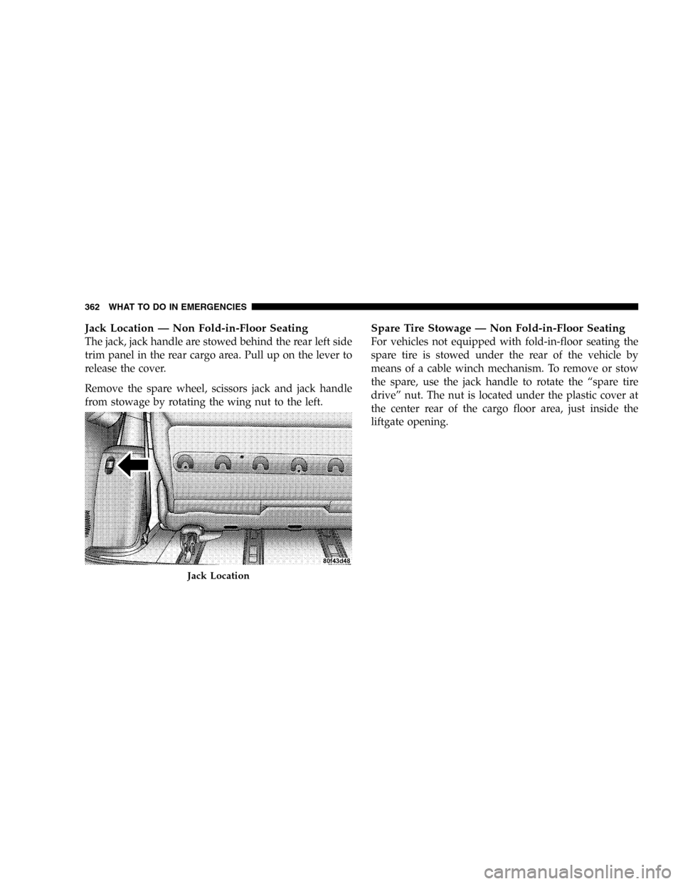
Jack Location—Non Fold-in-Floor Seating
The jack, jack handle are stowed behind the rear left side
trim panel in the rear cargo area. Pull up on the lever to
release the cover.
Remove the spare wheel, scissors jack and jack handle
from stowage by rotating the wing nut to the left.
Spare Tire Stowage—Non Fold-in-Floor Seating
For vehicles not equipped with fold-in-floor seating the
spare tire is stowed under the rear of the vehicle by
means of a cable winch mechanism. To remove or stow
the spare, use the jack handle to rotate the“spare tire
drive”nut. The nut is located under the plastic cover at
the center rear of the cargo floor area, just inside the
liftgate opening.
Jack Location
362 WHAT TO DO IN EMERGENCIES