ignition CHRYSLER TOWN AND COUNTRY 2008 5.G Owners Manual
[x] Cancel search | Manufacturer: CHRYSLER, Model Year: 2008, Model line: TOWN AND COUNTRY, Model: CHRYSLER TOWN AND COUNTRY 2008 5.GPages: 531, PDF Size: 4.51 MB
Page 439 of 531
This vehicle has a simple ignition key-actuated test,
which you can use prior to going to the test station. To
check if this vehicle's OBD II system is ready, you must
do the following:
1. Insert the ignition key into the ignition switch.
2. Turn the ignition to the ON position, but do not crank
or start the engine.
3. If you crank or start the engine, you will have to start
this test over.
4. As soon as you turn the ignition key to the ON
position, you will see the MIL symbol come on as part of
a normal bulb check.
5. Approximately 15 seconds later, one of two things will
happen:
a. The MIL will flash for about 10 seconds and then
return to being fully illuminated until you turn OFFthe ignition key or start the engine. This means that the
vehicle's OBD II system isnot readyand you should
notproceed to the I/M station.
b. The MIL will not flash at all and will remain fully
illuminated until you turn OFF the ignition key or start
the engine. This means that the vehicle's OBD II
system isready,and you can proceed to the I/M
station.
If the OBD II system isnot ready,you should see an
authorized dealer or repair facility. If this vehicle was
recently serviced or had a battery failure or replacement,
you may need to do nothing more than drive the vehicle
as you normally would in order for the OBD II system to
update. A recheck with the above test routine may then
indicate that the system is now ready.
Regardless of whether the vehicle's OBD II system is
ready or not ready, if the MIL is illuminated during
normal vehicle operation, you should have the vehicle
MAINTAINING YOUR VEHICLE 437
7
Page 447 of 531
WARNING!
A hot exhaust system can start a fire if you park over
materials that can burn. Such materials might be
grass or leaves coming into contact with your exhaust
system. Do not park or operate your vehicle in areas
where your exhaust system can contact anything that
can burn.
In unusual situations involving grossly malfunctioning
engine operation, a scorching odor may indicate severe
and abnormal catalyst overheating. If this occurs, the
vehicle should be stopped, the engine shut off and the
vehicle allowed to cool. Thereafter, service, including a
tune-up to manufacturer's specifications, should be ob-
tained immediately.To minimize the possibility of catalyst damage:²Do not shut off the engine or interrupt the ignition
when the transaxle is in gear and the vehicle is in
motion.
²Do not try to start engine by pushing or towing the
vehicle.
²Do not idle the engine with any spark plug wires
disconnected or removed, such as when diagnostic
testing, or for prolonged periods during very rough
idling or malfunctioning operating conditions.
MAINTAINING YOUR VEHICLE 445
7
Page 456 of 531
COOLING SYSTEM
WARNING!
²When working near the radiator cooling fan, dis-
connect the fan motor lead or turn the ignition
switch to the OFF position. The fan is temperature
controlled and can start at anytime the ignition
switch is in the ON position.
²You or others can be badly burned by hot coolant
or steam from your radiator. If you see or hear
steam coming from under the hood, don't open the
hood until the radiator has had time to cool. Never
try to open a cooling system pressure cap when the
radiator is hot.
Coolant Checks
Check the engine coolant (antifreeze) protection every 12
months (before the onset of freezing weather, where
applicable). If coolant is dirty or rusty in appearance, the
system should be drained, flushed and refilled with fresh
coolant. Check the front of the A/C condenser for any
accumulation of bugs, leaves, etc. If dirty, clean by gently
spraying water from a garden hose vertically down the
face of the condenser.
Check the coolant recovery bottle tubing for brittle rub-
ber, cracking, tears, cuts and tightness of the connection
at the bottle and radiator. Inspect the entire system for
leaks.
With the engine at normal operating temperature (but
not running), check the cooling system pressure cap for
proper vacuum sealing by draining a small amount of
coolant from the radiator drain cock. If the cap is sealing
properly, the engine coolant (antifreeze) will begin to
454 MAINTAINING YOUR VEHICLE
Page 475 of 531
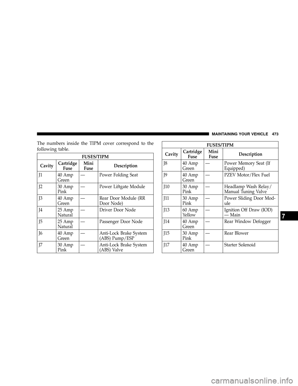
The numbers inside the TIPM cover correspond to the
following table.
FUSES/TIPM
CavityCartridge
FuseMini
FuseDescription
J1 40 Amp
GreenÐ Power Folding Seat
J2 30 Amp
PinkÐ Power Liftgate Module
J3 40 Amp
GreenÐ Rear Door Module (RR
Door Node)
J4 25 Amp
NaturalÐ Driver Door Node
J5 25 Amp
NaturalÐ Passenger Door Node
J6 40 Amp
GreenÐ Anti-Lock Brake System
(ABS) Pump/ESP
J7 30 Amp
PinkÐ Anti-Lock Brake System
(ABS) Valve
FUSES/TIPM
CavityCartridge
FuseMini
FuseDescription
J8 40 Amp
GreenÐ Power Memory Seat (If
Equipped)
J9 40 Amp
GreenÐ PZEV Motor/Flex Fuel
J10 30 Amp
PinkÐ Headlamp Wash Relay/
Manual Tuning Valve
J11 30 Amp
PinkÐ Power Sliding Door Mod-
ule
J13 60 Amp
YellowÐ Ignition Off Draw (IOD)
Ð Main
J14 40 Amp
GreenÐ Rear Window Defogger
J15 30 Amp
PinkÐ Rear Blower
J17 40 Amp
GreenÐ Starter Solenoid
MAINTAINING YOUR VEHICLE 473
7
Page 477 of 531
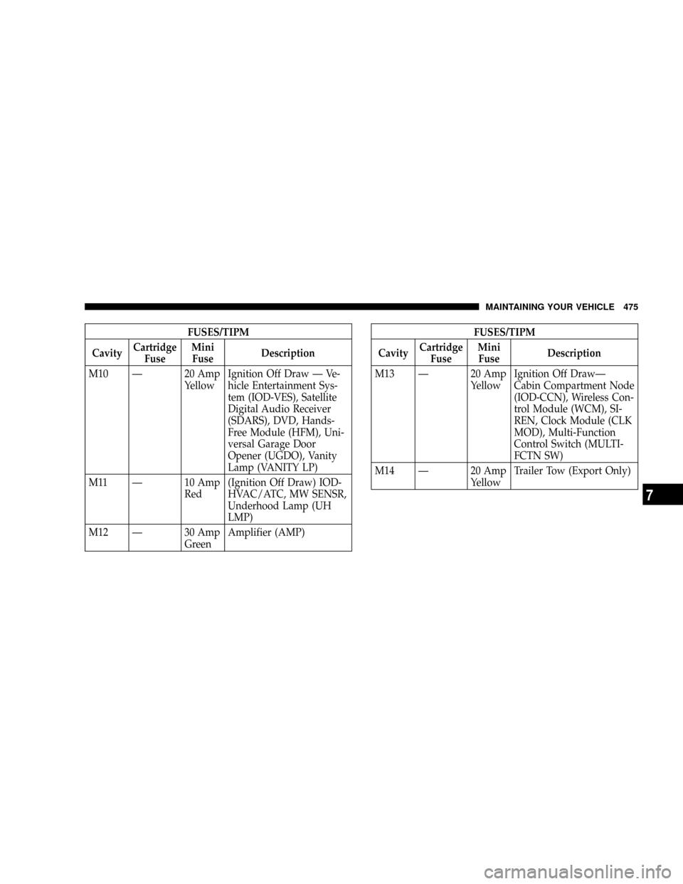
FUSES/TIPM
CavityCartridge
FuseMini
FuseDescription
M10 Ð 20 Amp
YellowIgnition Off Draw Ð Ve-
hicle Entertainment Sys-
tem (IOD-VES), Satellite
Digital Audio Receiver
(SDARS), DVD, Hands-
Free Module (HFM), Uni-
versal Garage Door
Opener (UGDO), Vanity
Lamp (VANITY LP)
M11 Ð 10 Amp
Red(Ignition Off Draw) IOD-
HVAC/ATC, MW SENSR,
Underhood Lamp (UH
LMP)
M12 Ð 30 Amp
GreenAmplifier (AMP)FUSES/TIPM
CavityCartridge
FuseMini
FuseDescription
M13 Ð 20 Amp
YellowIgnition Off DrawÐ
Cabin Compartment Node
(IOD-CCN), Wireless Con-
trol Module (WCM), SI-
REN, Clock Module (CLK
MOD), Multi-Function
Control Switch (MULTI-
FCTN SW)
M14 Ð 20 Amp
YellowTrailer Tow (Export Only)
MAINTAINING YOUR VEHICLE 475
7
Page 479 of 531
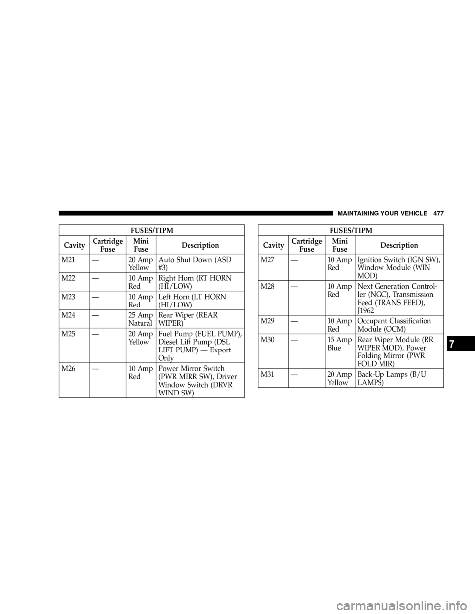
FUSES/TIPM
CavityCartridge
FuseMini
FuseDescription
M21 Ð 20 Amp
YellowAuto Shut Down (ASD
#3)
M22 Ð 10 Amp
RedRight Horn (RT HORN
(HI/LOW)
M23 Ð 10 Amp
RedLeft Horn (LT HORN
(HI/LOW)
M24 Ð 25 Amp
NaturalRear Wiper (REAR
WIPER)
M25 Ð 20 Amp
YellowFuel Pump (FUEL PUMP),
Diesel Lift Pump (DSL
LIFT PUMP) Ð Export
Only
M26 Ð 10 Amp
RedPower Mirror Switch
(PWR MIRR SW), Driver
Window Switch (DRVR
WIND SW)FUSES/TIPM
CavityCartridge
FuseMini
FuseDescription
M27 Ð 10 Amp
RedIgnition Switch (IGN SW),
Window Module (WIN
MOD)
M28 Ð 10 Amp
RedNext Generation Control-
ler (NGC), Transmission
Feed (TRANS FEED),
J1962
M29 Ð 10 Amp
RedOccupant Classification
Module (OCM)
M30 Ð 15 Amp
BlueRear Wiper Module (RR
WIPER MOD), Power
Folding Mirror (PWR
FOLD MIR)
M31 Ð 20 Amp
YellowBack-Up Lamps (B/U
LAMPS)
MAINTAINING YOUR VEHICLE 477
7
Page 481 of 531
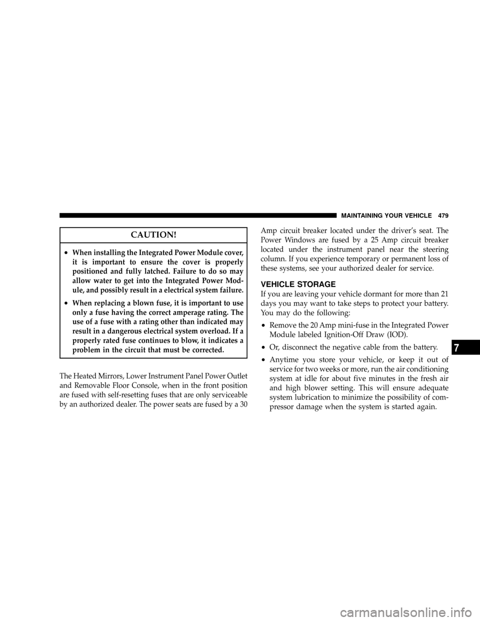
CAUTION!
²When installing the Integrated Power Module cover,
it is important to ensure the cover is properly
positioned and fully latched. Failure to do so may
allow water to get into the Integrated Power Mod-
ule, and possibly result in a electrical system failure.
²When replacing a blown fuse, it is important to use
only a fuse having the correct amperage rating. The
use of a fuse with a rating other than indicated may
result in a dangerous electrical system overload. If a
properly rated fuse continues to blow, it indicates a
problem in the circuit that must be corrected.
The Heated Mirrors, Lower Instrument Panel Power Outlet
and Removable Floor Console, when in the front position
are fused with self-resetting fuses that are only serviceable
by an authorized dealer. The power seats are fused by a 30Amp circuit breaker located under the driver's seat. The
Power Windows are fused by a 25 Amp circuit breaker
located under the instrument panel near the steering
column. If you experience temporary or permanent loss of
these systems, see your authorized dealer for service.
VEHICLE STORAGE
If you are leaving your vehicle dormant for more than 21
days you may want to take steps to protect your battery.
You may do the following:
²Remove the 20 Amp mini-fuse in the Integrated Power
Module labeled Ignition-Off Draw (IOD).
²Or, disconnect the negative cable from the battery.
²Anytime you store your vehicle, or keep it out of
service for two weeks or more, run the air conditioning
system at idle for about five minutes in the fresh air
and high blower setting. This will ensure adequate
system lubrication to minimize the possibility of com-
pressor damage when the system is started again.
MAINTAINING YOUR VEHICLE 479
7
Page 496 of 531
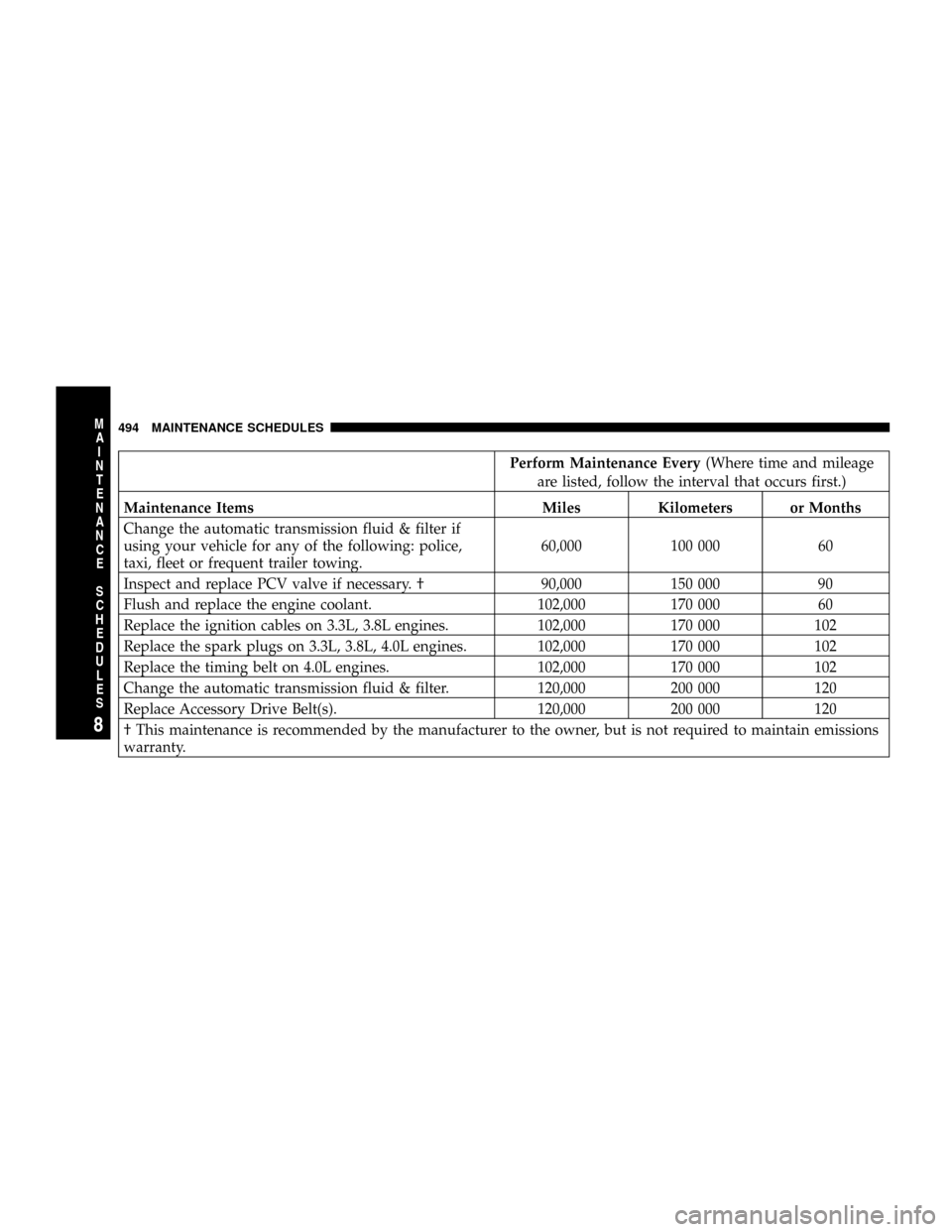
Perform Maintenance Every(Where time and mileage
are listed, follow the interval that occurs first.)
Maintenance Items Miles Kilometers or Months
Change the automatic transmission fluid & filter if
using your vehicle for any of the following: police,
taxi, fleet or frequent trailer towing.60,000 100 000 60
Inspect and replace PCV valve if necessary. ² 90,000 150 000 90
Flush and replace the engine coolant. 102,000 170 000 60
Replace the ignition cables on 3.3L, 3.8L engines. 102,000 170 000 102
Replace the spark plugs on 3.3L, 3.8L, 4.0L engines. 102,000 170 000 102
Replace the timing belt on 4.0L engines. 102,000 170 000 102
Change the automatic transmission fluid & filter. 120,000 200 000 120
Replace Accessory Drive Belt(s). 120,000 200 000 120
² This maintenance is recommended by the manufacturer to the owner, but is not required to maintain emissions
warranty.
494 MAINTENANCE SCHEDULES
8
M
A
I
N
T
E
N
A
N
C
E
S
C
H
E
D
U
L
E
S
Page 518 of 531
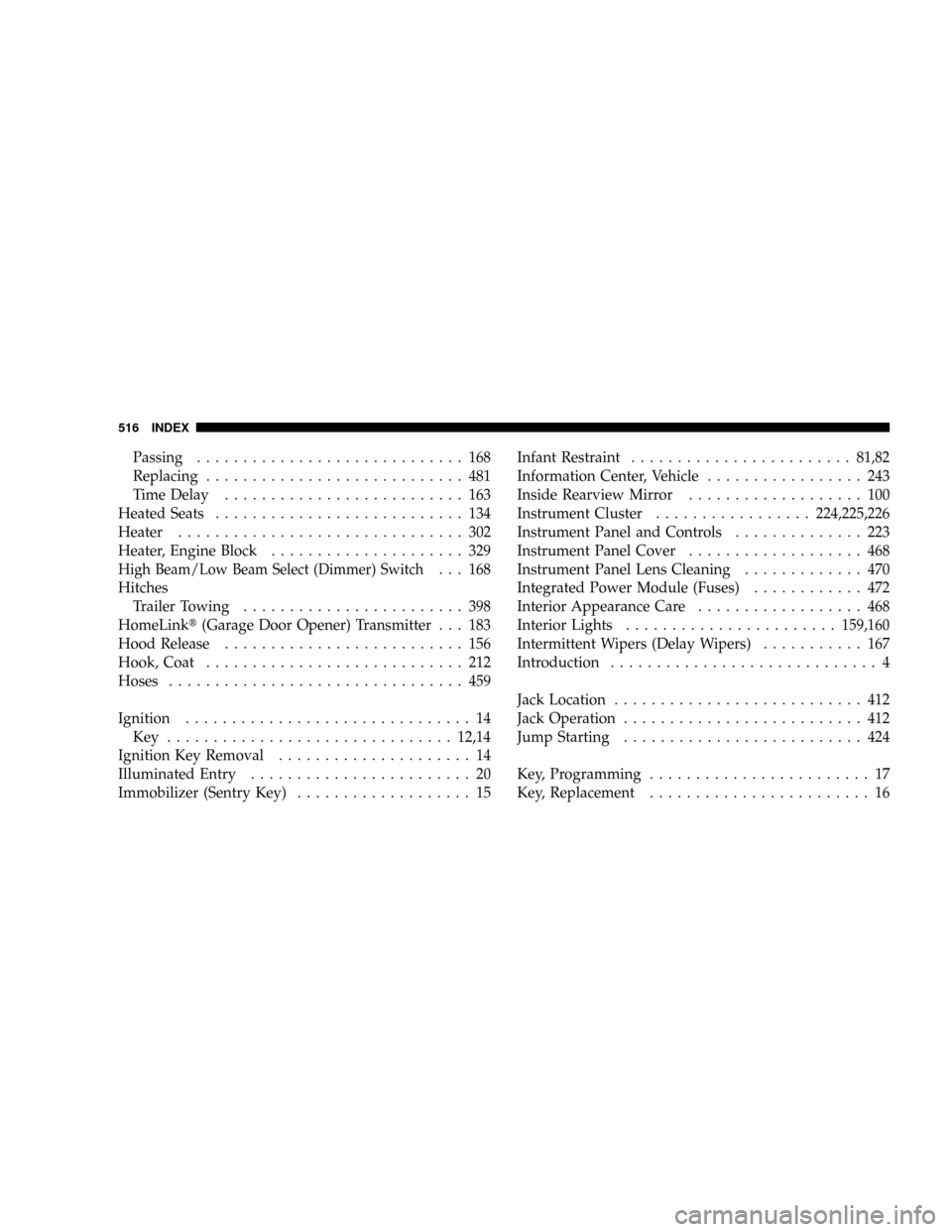
Passing............................. 168
Replacing............................ 481
Time Delay.......................... 163
Heated Seats........................... 134
Heater............................... 302
Heater, Engine Block..................... 329
High Beam/Low Beam Select (Dimmer) Switch... 168
Hitches
Trailer Towing........................ 398
HomeLinkt(Garage Door Opener) Transmitter . . . 183
Hood Release.......................... 156
Hook, Coat............................ 212
Hoses................................ 459
Ignition............................... 14
Key ...............................12,14
Ignition Key Removal..................... 14
Illuminated Entry........................ 20
Immobilizer (Sentry Key)................... 15Infant Restraint........................81,82
Information Center, Vehicle................. 243
Inside Rearview Mirror................... 100
Instrument Cluster.................224,225,226
Instrument Panel and Controls.............. 223
Instrument Panel Cover................... 468
Instrument Panel Lens Cleaning............. 470
Integrated Power Module (Fuses)............ 472
Interior Appearance Care.................. 468
Interior Lights.......................159,160
Intermittent Wipers (Delay Wipers)........... 167
Introduction............................. 4
Jack Location........................... 412
Jack Operation.......................... 412
Jump Starting.......................... 424
Key, Programming........................ 17
Key, Replacement........................ 16
516 INDEX