tires CHRYSLER TOWN AND COUNTRY 2008 5.G Owners Manual
[x] Cancel search | Manufacturer: CHRYSLER, Model Year: 2008, Model line: TOWN AND COUNTRY, Model: CHRYSLER TOWN AND COUNTRY 2008 5.GPages: 531, PDF Size: 4.51 MB
Page 96 of 531
PERIODIC SAFETY CHECKS YOU SHOULD MAKE
OUTSIDE THE VEHICLE
Tires
Examine tires for excessive tread wear or uneven wear
patterns. Check for stones, nails, glass, or other objects
lodged in the tread. Inspect tread and sidewall for cuts or
cracks. Check wheel nuts for tightness, and tires (includ-
ing spare) for proper pressure.
Lights
Have someone observe the operation of exterior lights
while you work the controls. Check turn signal and high
beam indicator lights on the instrument panel.
Fluid Leaks
Check area under vehicle after overnight parking for fuel,
engine coolant, oil or other fluid leaks. Also, if gasoline
fumes are detected or fuel, power steering fluid, trans-
mission fluid or brake fluid leaks are suspected, the cause
should be located and corrected immediately.
Exhaust Gas
WARNING!
Exhaust gases can injure or kill. They contain carbon
monoxide (CO) which is colorless and odorless.
Breathing it can make you unconscious and can
eventually poison you. To avoid breathing (CO)
follow the safety tips below.
Do not run the engine in a closed garage or in confined
areas any longer than needed to move your vehicle in or
out of the area.
If it is necessary to sit in a parked vehicle with the engine
running, adjust your heating or cooling controls to force
outside air into the vehicle. Set the blower at high speed.
94 THINGS TO KNOW BEFORE STARTING YOUR VEHICLE
Page 104 of 531
Side View Manual Folding Mirrors
All exterior mirrors are hinged and may be moved either
forward or rearward to resist damage. The hinges have
three detent positions; full forward, full rearward, and
normal.
Driver's Auto-Dimming Side View Mirror Ð If
Equipped
This mirror automatically adjusts for annoying headlight
glare from vehicles behind you. You can turn this feature
on or off by pressing the button at the base of the
Rearview Mirror.
Tilt In Reverse Feature Driver's Side View Mirror
Ð If Equipped
The9Tilt in Reverse9feature tilts the driver's outside
rearview mirror downward when the ignition switch is
in the ON position and the transmission is in the RE-
VERSE position. This feature provides the driver with a
better view of the ground and vehicle in the area of the
rear tires when backing up. The mirror will move back to
its previous position when the transmission is shifted out
of REVERSE.
Power Remote Folding Side View Mirrors Ð If
Equipped
Press the power fold button to fold in the mirrors. Press
the button again to unfold the mirrors.
102 UNDERSTANDING THE FEATURES OF YOUR VEHICLE
Page 229 of 531
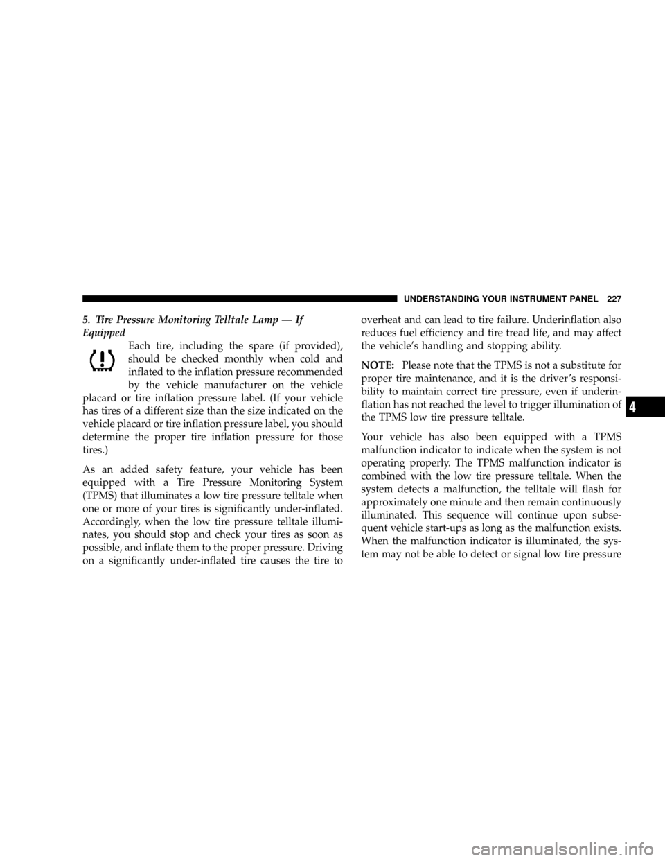
5. Tire Pressure Monitoring Telltale Lamp Ð If
Equipped
Each tire, including the spare (if provided),
should be checked monthly when cold and
inflated to the inflation pressure recommended
by the vehicle manufacturer on the vehicle
placard or tire inflation pressure label. (If your vehicle
has tires of a different size than the size indicated on the
vehicle placard or tire inflation pressure label, you should
determine the proper tire inflation pressure for those
tires.)
As an added safety feature, your vehicle has been
equipped with a Tire Pressure Monitoring System
(TPMS) that illuminates a low tire pressure telltale when
one or more of your tires is significantly under-inflated.
Accordingly, when the low tire pressure telltale illumi-
nates, you should stop and check your tires as soon as
possible, and inflate them to the proper pressure. Driving
on a significantly under-inflated tire causes the tire tooverheat and can lead to tire failure. Underinflation also
reduces fuel efficiency and tire tread life, and may affect
the vehicle's handling and stopping ability.
NOTE:Please note that the TPMS is not a substitute for
proper tire maintenance, and it is the driver 's responsi-
bility to maintain correct tire pressure, even if underin-
flation has not reached the level to trigger illumination of
the TPMS low tire pressure telltale.
Your vehicle has also been equipped with a TPMS
malfunction indicator to indicate when the system is not
operating properly. The TPMS malfunction indicator is
combined with the low tire pressure telltale. When the
system detects a malfunction, the telltale will flash for
approximately one minute and then remain continuously
illuminated. This sequence will continue upon subse-
quent vehicle start-ups as long as the malfunction exists.
When the malfunction indicator is illuminated, the sys-
tem may not be able to detect or signal low tire pressure
UNDERSTANDING YOUR INSTRUMENT PANEL 227
4
Page 230 of 531
as intended. TPMS malfunctions may occur for a variety
of reasons, including the installation of replacement or
alternate tires or wheels on the vehicle that prevent the
TPMS from functioning properly.
NOTE:Always check the TPMS malfunction telltale
after replacing one or more tires or wheels on your
vehicle to ensure that the replacement or alternate tires
and wheels allow the TPMS to continue to function
properly.CAUTION!
The TPMS has been optimized for the original
equipment tires and wheels. TPMS pressures and
warning have been established for the tire size
equipped on your vehicle. Undesirable system opera-
tion or sensor damage may result when using re-
placement equipment that is not of the same size,
type, and/or style. Aftermarket wheels can cause
sensor damage. Do not use aftermarket tire sealants
or balance beads if your vehicle is equipped with a
TPMS, as damage to the sensors may result.
For additional information on TPMS, refer to Section 5 Ð
Starting and Operating, ªTire Pressure Monitoring Sys-
temº of this manual.
228 UNDERSTANDING YOUR INSTRUMENT PANEL
Page 326 of 531
mDriving Through Water..................349
NFlowing/Rising Water..................349
mTire Safety Information...................351
NTire Markings........................351
NTire Loading And Tire Pressure...........355
mTires Ð General Information...............359
NTire Pressure.........................359
mTire Chains...........................368
mSnow Tires...........................369
mTire Rotation..........................369
mTire Pressure Monitor System (TPMS)........370
NBasic TPMS Without EVIC Ð If Equipped....372
NPremium TPMS With EVIC Ð If Equipped . . . 374mFuel Requirements......................379
N3.3L & 3.8L Gasoline Engine..............379
N4.0L Gasoline Engine...................379
mAdding Fuel..........................383
NFuel Filler Cap (Gas Cap)...............383
NLoose Fuel Filler Cap Message............385
mFlexible Fuel Ð 3.3L Engines Only..........386
NE-85 General Information................386
NEthanol Fuel (E-85)....................387
NFuel Requirements....................387
NSelection Of Engine Oil For Flexible Fuel
Vehicles (Ffv) E-85 And Gasoline Vehicles....388
NStarting............................388
324 STARTING AND OPERATING
Page 343 of 531
²A slight drop or fall away of the brake pedal at the end
of the stop.
WARNING!
²The Anti-Lock Brake System contains sophisti-
cated electronic equipment that may be suscep-
tible to interference caused by improperly in-
stalled or high output radio transmitting
equipment. This interference can cause possible
loss of anti-lock braking capability. Installation of
such equipment should be performed by qualified
professionals.
²Pumping of the Anti-Lock Brakes will diminish
their effectiveness and may lead to an accident.
Pumping makes the stopping distance longer. Just
press firmly on your brake pedal when you need
to slow down or stop.
WARNING!
²The Anti-Lock Brake System cannot prevent acci-
dents, including those resulting from excessive
speed in turns, following another vehicle too
closely, or hydroplaning. Only a safe, attentive,
and skillful driver can prevent accidents.
²The capabilities of an ABS-equipped vehicle must
never be exploited in a reckless or dangerous
manner which could jeopardize the user's safety
or the safety of others.
All vehicle wheels and tires must be the same size and
type, and tires must be properly inflated to produce
accurate signals for the computer.
STARTING AND OPERATING 341
5
Page 345 of 531
spinning faster than the other, the system will apply the
brake of the spinning wheel. This will allow more engine
torque to be applied to the wheel that is not spinning.
This feature remains active even if the ESP is in the
ªPartial Offº mode.
The Traction Control System (TCS) Indicator
Light, located in the instrument cluster, starts
to flash as soon as the tires lose traction and the
wheels begin to spin. This indicates that the
TCS is active. If the indicator light flashes during accel-
eration, ease up on the accelerator and apply as little
throttle as possible. Be sure to adapt your speed and
driving to the prevailing road conditions, and do not
switch off the ESP or TCS.WARNING!
²The TCS cannot prevent the natural laws of phys-
ics from acting on the vehicle, nor can it increase
the traction afforded.
²The TCS cannot prevent accidents, including those
resulting from excessive speed in turns, or hydro-
planing. Only a safe, attentive, and skillful driver
can prevent accidents.
²The capabilities of a TCS-equipped vehicle must
never be exploited in a reckless or dangerous
manner, which could jeopardize the user's safety
or the safety of others.
STARTING AND OPERATING 343
5
Page 350 of 531
DRIVING ON SLIPPERY SURFACES
ACCELERATION
Rapid acceleration on snow covered, wet, or other slip-
pery surfaces may cause the front wheels to pull errati-
cally to the right or left. This phenomenon occurs when
there is a difference in the surface traction under the front
(driving) wheels.
WARNING!
Rapid acceleration on slippery surfaces is dangerous.
Unequal traction can cause sudden pulling of the
front wheels. You could lose control of the vehicle
and possibly have an accident. Accelerate slowly and
carefully whenever there is likely to be poor traction
(ice, snow, wet mud, loose sand, etc.).
TRACTION
When driving on wet or slushy roads, it is possible for a
wedge of water to build up between the tire and road
surface. This is known as hydroplaning and may cause
partial or complete loss of vehicle control and stopping
ability. To reduce this possibility, the following precau-
tions should be observed:
1. Slow down during rainstorms or when roads are
slushy.
2. Slow down if the road has standing water or puddles.
3. Replace the tires when tread wear indicators first
become visible.
4. Keep the tires properly inflated.
5. Maintain sufficient distance between your vehicle and
the vehicle in front of you to avoid a collision in a sudden
stop.
348 STARTING AND OPERATING
Page 353 of 531
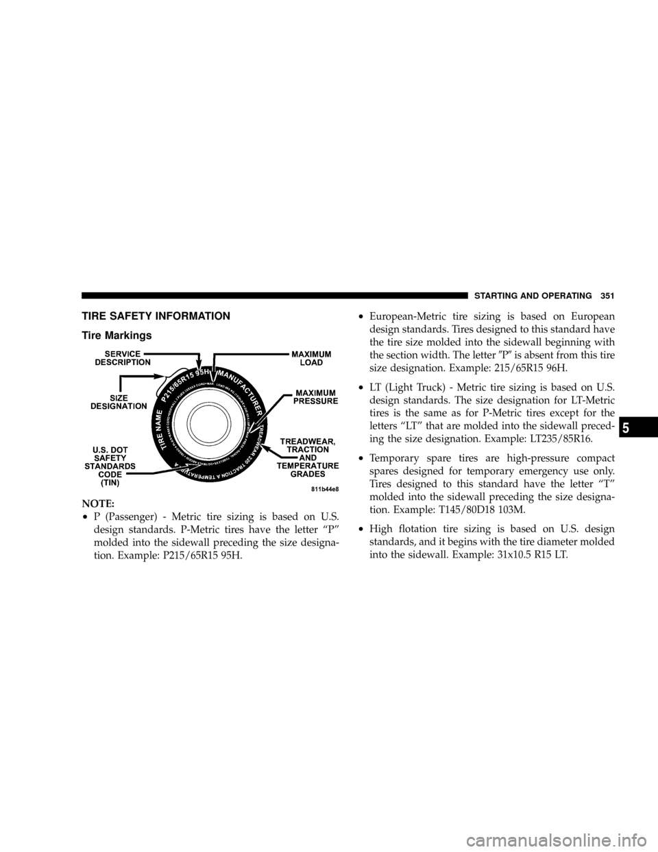
TIRE SAFETY INFORMATION
Tire Markings
NOTE:
²P (Passenger) - Metric tire sizing is based on U.S.
design standards. P-Metric tires have the letter ªPº
molded into the sidewall preceding the size designa-
tion. Example: P215/65R15 95H.
²European-Metric tire sizing is based on European
design standards. Tires designed to this standard have
the tire size molded into the sidewall beginning with
the section width. The letter9P9is absent from this tire
size designation. Example: 215/65R15 96H.
²LT (Light Truck) - Metric tire sizing is based on U.S.
design standards. The size designation for LT-Metric
tires is the same as for P-Metric tires except for the
letters ªLTº that are molded into the sidewall preced-
ing the size designation. Example: LT235/85R16.
²Temporary spare tires are high-pressure compact
spares designed for temporary emergency use only.
Tires designed to this standard have the letter ªTº
molded into the sidewall preceding the size designa-
tion. Example: T145/80D18 103M.
²High flotation tire sizing is based on U.S. design
standards, and it begins with the tire diameter molded
into the sidewall. Example: 31x10.5 R15 LT.
STARTING AND OPERATING 351
5
Page 356 of 531
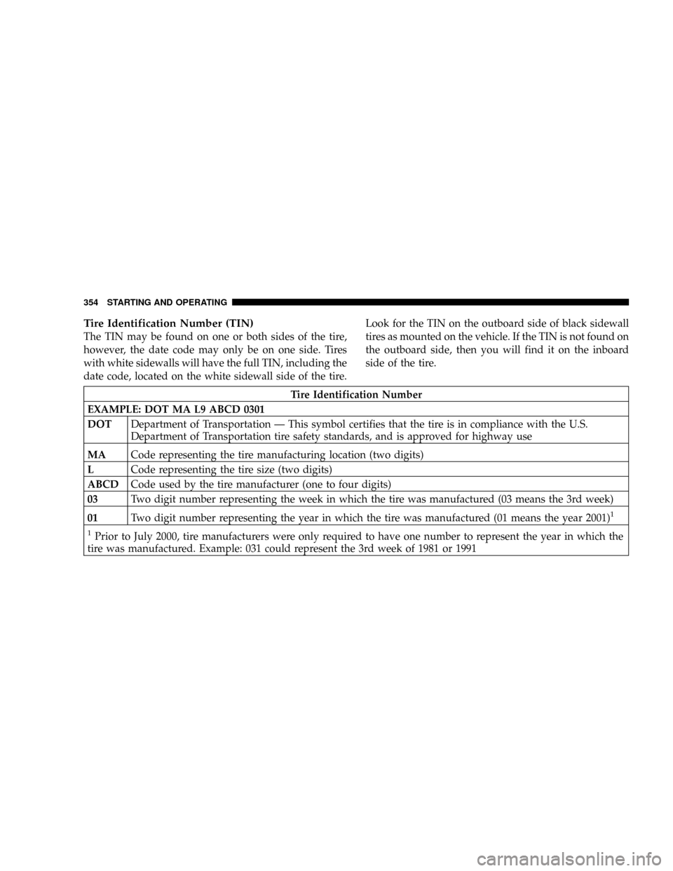
Tire Identification Number (TIN)
The TIN may be found on one or both sides of the tire,
however, the date code may only be on one side. Tires
with white sidewalls will have the full TIN, including the
date code, located on the white sidewall side of the tire.Look for the TIN on the outboard side of black sidewall
tires as mounted on the vehicle. If the TIN is not found on
the outboard side, then you will find it on the inboard
side of the tire.
Tire Identification Number
EXAMPLE: DOT MA L9 ABCD 0301
DOTDepartment of Transportation Ð This symbol certifies that the tire is in compliance with the U.S.
Department of Transportation tire safety standards, and is approved for highway use
MACode representing the tire manufacturing location (two digits)
LCode representing the tire size (two digits)
ABCDCode used by the tire manufacturer (one to four digits)
03Two digit number representing the week in which the tire was manufactured (03 means the 3rd week)
01Two digit number representing the year in which the tire was manufactured (01 means the year 2001)
1
1
Prior to July 2000, tire manufacturers were only required to have one number to represent the year in which the
tire was manufactured. Example: 031 could represent the 3rd week of 1981 or 1991
354 STARTING AND OPERATING