instrument panel CHRYSLER TOWN AND COUNTRY 2010 5.G User Guide
[x] Cancel search | Manufacturer: CHRYSLER, Model Year: 2010, Model line: TOWN AND COUNTRY, Model: CHRYSLER TOWN AND COUNTRY 2010 5.GPages: 92, PDF Size: 11.08 MB
Page 18 of 92
• To program a Key Fob to the memory position, press and release the LOCK buttonwithin 10 seconds on the Key Fob to be programmed.
• Place the ignition switch in the ON position, select Remote Linked to Memory in the Electronic Vehicle Information Center (EVIC) and enter Yes.
• Press 1 or 2 to recall the saved positions, or press UNLOCK on the programmed Key Fo b .
HEATED SEATS
Front Heated Seats
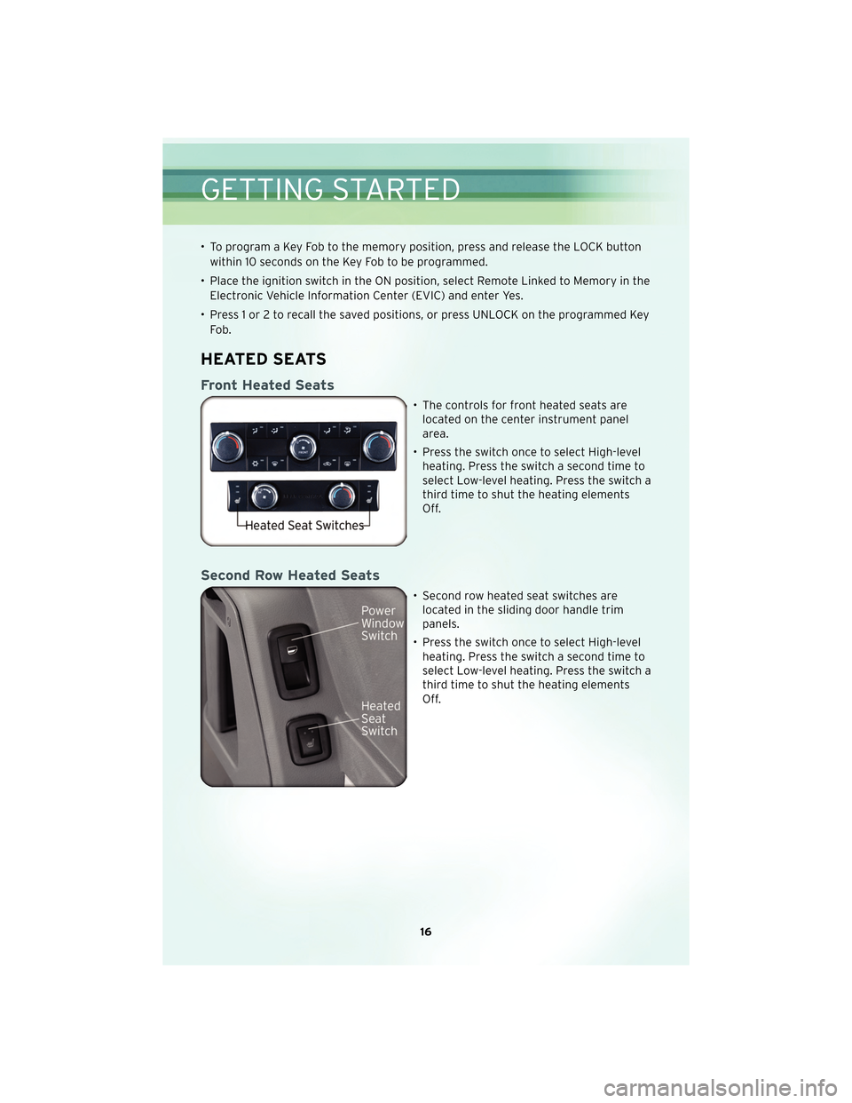
• The controls for front heated seats arelocated on the center instrument panel
area.
• Press the switch once to select High-level heating. Press the switch a second time to
select Low-level heating. Press the switch a
third time to shut the heating elements
Off.
Second Row Heated Seats
• Second row heated seat switches arelocated in the sliding door handle trim
panels.
• Press the switch once to select High-level heating. Press the switch a second time to
select Low-level heating. Press the switch a
third time to shut the heating elements
Off.
GETTING STARTED
16
Page 24 of 92
Rear Washer
• Rotate the center portion of the lever past the first detent to activate the rearwasher.
High Beams
• Push the lever away from you to activate the high beams.
• A high beam symbol will illuminate in the cluster to indicate the high beams are on.
NOTE: For safe driving, turn off high beams when oncoming traffic is present to
prevent headlight glare and as a courtesy to other motorists.
HEADLIGHT SWITCH AND HALO LIGHT SWITCH
Automatic Headlights/Parking
Lights/Headlights
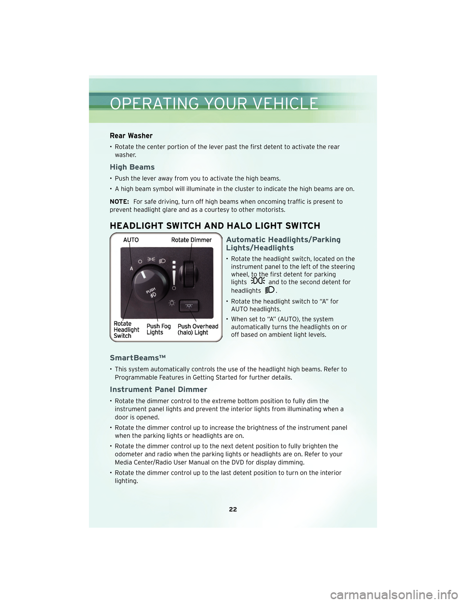
• Rotate the headlight switch, located on the instrument panel to the left of the steering
wheel, to the first detent for parking
lights
and to the second detent for
headlights
.
• Rotate the headlight switch to “A” for AUTO headlights.
• When set to “A” (AUTO), the system automatically turns the headlights on or
off based on ambient light levels.
SmartBeams™
• This system automatically controls the use of the headlight high beams. Refer to
Programmable Features in Getting Started for further details.
Instrument Panel Dimmer
• Rotate the dimmer control to the extreme bottom position to fully dim theinstrument panel lights and prevent the interior lights from illuminating when a
door is opened.
• Rotate the dimmer control up to increase the brightness of the instrument panel when the parking lights or headlights are on.
• Rotate the dimmer control up to the next detent position to fully brighten the odometer and radio when the parking lights or headlights are on. Refer to your
Media Center/Radio User Manual on the DVD for display dimming.
• Rotate the dimmer control up to the last detent position to turn on the interior lighting.
OPERATING YOUR VEHICLE
22
Page 29 of 92

Activating Rear Passenger Climate Controls
• Rotate the rear blower control, located on the main climate control in theinstrument panel, to the “RR” position. This enables the rear passenger climate
controls located in the headliner above the second row seats.
FRONT THREE ZONE AUTOMATIC TEMPERATURE
CONTROLS (ATC)
27
OPERATING YOUR VEHICLE
Page 31 of 92
Activating Rear Automatic Temperature Control
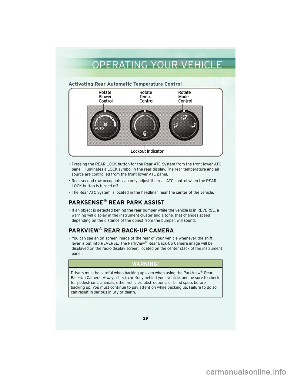
• Pressing the REAR LOCK button for the Rear ATC System from the front lower ATCpanel, illuminates a LOCK symbol in the rear display. The rear temperature and air
source are controlled from the front lower ATC panel.
• Rear second row occupants can only adjust the rear ATC control when the REAR LOCK button is turned off.
• The Rear ATC System is located in the headliner, near the center of the vehicle.
PARKSENSE®REAR PARK ASSIST
• If an object is detected behind the rear bumper while the vehicle is in REVERSE, a warning will display in the instrument cluster and a tone, that changes speed
depending on the distance of the object from the bumper, will sound.
PARKVIEW®REAR BACK-UP CAMERA
• You can see an on-screen image of the rear of your vehicle whenever the shiftlever is put into REVERSE. The ParkView®Rear Back-Up Camera image will be
displayed on the radio display screen, located on the center stack of the instrument
panel.
WARNING!
Drivers must be careful when backing up even when using the ParkView®Rear
Back-Up Camera. Always check carefully behind your vehicle, and be sure to check
for pedestrians, animals, other vehicles, obstructions, or blind spots before
backing up. You must continue to pay attention while backing up. Failure to do so
can result in serious injury or death.
29
OPERATING YOUR VEHICLE
Page 48 of 92
Programming A Rolling Code System
• At the garage door opener motor (in the garage), locate the “learn” or“programming” button. This can usually be found where the hanging antenna wire
is attached to the garage door opener motor (it is NOT the button normally used to
open and close the door).
• Firmly press and release the “learn” or “programming” button. The name and color of the button may vary by manufacturer. Within 30 seconds, return to the vehicle
and press the programmed HomeLink
®button twice (holding the button for two
seconds each time). If the device is plugged in and activates, programming is
complete.
• If the device does not activate, press the button a third time (for two seconds) to complete the programming.
Using HomeLink®
• To operate, simply press and release the programmed HomeLink®button and the
programmed device will operate.
• Refer to your Owner’s Manual on the DVD for further details. If you have any problems programming HomeLink
®, or require assistance, please call toll-free
1–800–355–3515 or, on the Internet, at www.HomeLink.com.
POWER INVERTER
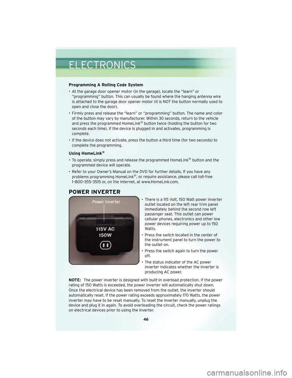
• There is a 115 Volt, 150 Watt power inverter outlet located on the left rear trim panel
immediately behind the second row left
passenger seat. This outlet can power
cellular phones, electronics and other low
power devices requiring power up to 150
Watts.
• Press the switch located in the center of the instrument panel to turn the power to
the outlet on.
• Press the switch again to turn the power off.
• The status indicator of the AC power inverter indicates whether the inverter is
producing AC power.
NOTE: The power inverter is designed with built-in overload protection. If the power
rating of 150 Watts is exceeded, the power inverter will automatically shut down.
Once the electrical device has been removed from the outlet, the inverter should
automatically reset. If the power rating exceeds approximately 170 Watts, the power
inverter may have to be reset manually. To reset the inverter manually, unplug the
device and plug it in again. To avoid overloading the circuit, check the power ratings
on electrical devices prior to using the inverter.
ELECTRONICS
46
Page 49 of 92
WARNING!
To Avoid Serious Injury or Death: Do not use a three-prong adaptor. Do not insert
any objects into the receptacles. Do not touch with wet hands. Close the lid when
not in use. If this outlet is mishandled, it may cause an electric shock and failure.
POWER OUTLETS
• There are four 12 Volt power outlets in your vehicle.
• Two are located on the lower instrument panel, next to the open storage bin. Theupper power outlet is controlled by the ignition switch and the lower power outlet
is connected directly to the battery.
• One is located in the removable floor console and is also connected directly to the battery.
• One is located in the rear quarter panel near the liftgate. This outlet is also controlled by the ignition switch.
NOTE: Do not exceed the maximum power of 160 Watts (13 Amps) at 12 Volts. If the
160 Watt (13 Amp) power rating is exceeded the fuse protecting the system will need
to be replaced.
Uconnect™ Phone
• The Uconnect™ Phone is a voice-activated, hands-free, in-vehicle communications system.
• The Uconnect™ Phone allows you to dial a phone number with your cellular phone using simple voice commands.
• For vehicles equipped with Video Entertainment System (VES)™, refer to the Uconnect™ Phone section of the Uconnect™ User’s Manual on the DVD for further
details.
• For vehicles not equipped with VES™, refer to your vehicle Owner’s Manual on the DVD for further details.
WARNING!
• Any voice commanded system should be used only in safe driving conditionsfollowing local laws and phone use. All attention should be kept on the roadway
ahead. Failure to do so may result in an accident causing you and others to be
severely injured or killed.
• In an emergency to use Uconnect™ Phone, your cellular phone must be: • turned on,
• paired to Uconnect™ Phone,
• and have network coverage.
NOTE: The Uconnect™ Phone requires a cellular phone equipped with the
47
ELECTRONICS
Page 54 of 92
RECREATIONAL TOWING
(BEHIND MOTORHOME,
ETC.)
CAUTION!
Towing this vehicle behind another
vehicle (flat-towing with all four
wheels on the ground) is not
recommended.
NOTE: If the vehicle requires towing,
make sure all four wheels are off the
ground.
BRAKE/TRANSAXLE
INTERLOCK MANUAL
OVERRIDE
• The manual override may be used in the event that the shift lever should
fail to move from PARK with the Key
Fob in the ON position and the brake
pedal pr essed.
• To operate the shift lock manual override, perform the following
steps: • Remove the cover located to the
top right of the shift lever in the
instrument panel.
• The override can be activated by pressing the white-colored tab,
which can be acc essedthrough
the hole in the instrument panel.
• While the override is pressed, the
shift lever can be moved out of
the PARK position without
pressing the brake pedal. After
operation, return the cover to its
original position.
• Have your vehicle inspected by your local authorized dealer immediately
if the shift lock manual override has
been used.
NOTE: If a malfunction occurs, the
system will trap the Key Fob in the
ignition cylinder to warn you that this
safety feature is inoperable. The
engine can be started and stopped, but
the Key Fob cannot be removed until
you obtain service.
UTILITY
52
Page 70 of 92
OPENING THE HOOD
• Pull the hood release lever located on the instrument panel, below the steeringcolumn.
• Raise the hood and locate the safety catch lever, in the middle of the hood opening.
• Move the safety latch while lifting the hood at the same time.
• Insert the support rod into the slot on the hood.
• To close the hood, remove the support rod and place it in the retaining clip, then lower the hood slowly.
WARNING!
Be sure the hood is fully latched before driving your vehicle. If the hood is not fully
latched, it could open when the vehicle is in motion and block your vision. Failure
to follow this warning could result in serious injury or death.
ADDING FUEL
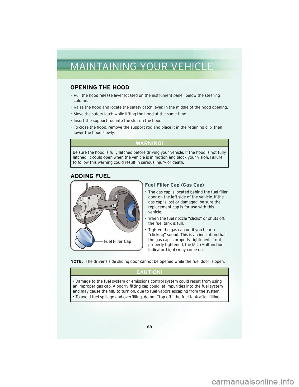
Fuel Filler Cap (Gas Cap)
• The gas cap is located behind the fuel fillerdoor on the left side of the vehicle. If the
gas cap is lost or damaged, be sure the
replacement cap is for use with this
vehicle.
• When the fuel nozzle “clicks” or shuts off, the fuel tank is full.
• Tighten the gas cap until you hear a “clicking” sound. This is an indication that
the gas cap is properly tightened. If not
properly tightened, the MIL (Malfunction
Indicator Light) may come on.
NOTE: The driver’s side sliding door cannot be opened while the fuel door is open.
CAUTION!
• Damage to the fuel system or emissions control system could result from using
an improper gas cap. A poorly fitting cap could let impurities into the fuel system
and may cause the MIL to turn on, due to fuel vapors escaping from the system.
• To avoid fuel spillage and overfilling, do not “top off” the fuel tank after filling.
MAINTAINING YOUR VEHICLE
68