CHRYSLER TOWN AND COUNTRY 2012 5.G Owners Manual
Manufacturer: CHRYSLER, Model Year: 2012, Model line: TOWN AND COUNTRY, Model: CHRYSLER TOWN AND COUNTRY 2012 5.GPages: 652, PDF Size: 11.05 MB
Page 591 of 652
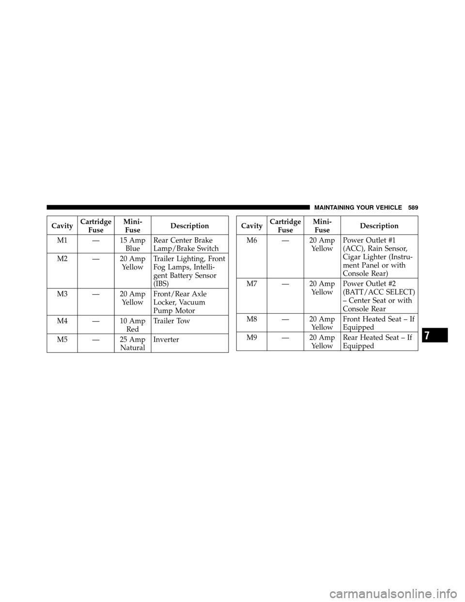
CavityCartridge
Fuse Mini-
Fuse Description
M1 — 15 Amp BlueRear Center Brake
Lamp/Brake Switch
M2 — 20 Amp YellowTrailer Lighting, Front
Fog Lamps, Intelli-
gent Battery Sensor
(IBS)
M3 — 20 Amp YellowFront/Rear Axle
Locker, Vacuum
Pump Motor
M4 — 10 Amp RedTrailer Tow
M5 — 25 Amp NaturalInverterCavity
Cartridge
Fuse Mini-
Fuse Description
M6 — 20 Amp YellowPower Outlet #1
(ACC), Rain Sensor,
Cigar Lighter (Instru-
ment Panel or with
Console Rear)
M7 — 20 Amp YellowPower Outlet #2
(BATT/ACC SELECT)
– Center Seat or with
Console Rear
M8 — 20 Amp YellowFront Heated Seat – If
Equipped
M9 — 20 Amp YellowRear Heated Seat – If
Equipped
7
MAINTAINING YOUR VEHICLE 589
Page 592 of 652
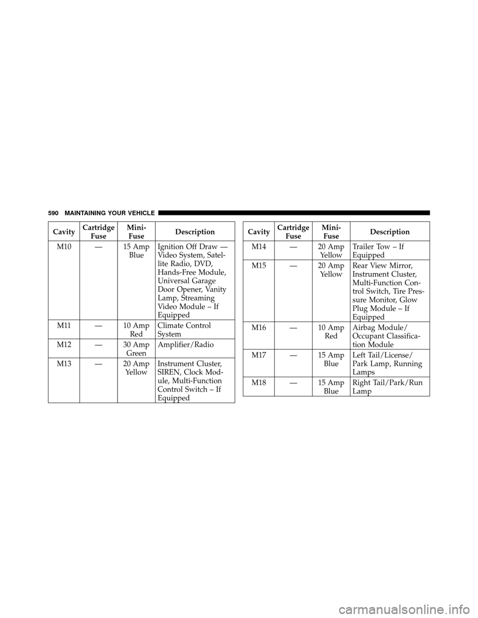
CavityCartridge
Fuse Mini-
Fuse Description
M10 — 15 Amp BlueIgnition Off Draw —
Video System, Satel-
lite Radio, DVD,
Hands-Free Module,
Universal Garage
Door Opener, Vanity
Lamp, Streaming
Video Module – If
Equipped
M11 — 10 Amp RedClimate Control
System
M12 — 30 Amp GreenAmplifier/Radio
M13 — 20 Amp YellowInstrument Cluster,
SIREN, Clock Mod-
ule, Multi-Function
Control Switch – If
EquippedCavity
Cartridge
Fuse Mini-
Fuse Description
M14 — 20 Amp YellowTrailer Tow – If
Equipped
M15 — 20 Amp YellowRear View Mirror,
Instrument Cluster,
Multi-Function Con-
trol Switch, Tire Pres-
sure Monitor, Glow
Plug Module – If
Equipped
M16 — 10 Amp RedAirbag Module/
Occupant Classifica-
tion Module
M17 — 15 Amp BlueLeft Tail/License/
Park Lamp, Running
Lamps
M18 — 15 Amp BlueRight Tail/Park/Run
Lamp
590 MAINTAINING YOUR VEHICLE
Page 593 of 652
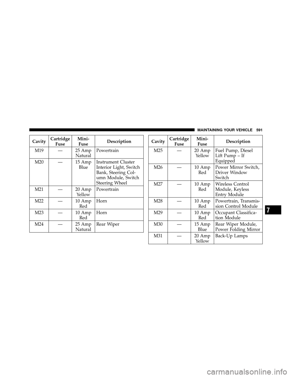
CavityCartridge
Fuse Mini-
Fuse Description
M19 — 25 Amp NaturalPowertrain
M20 — 15 Amp BlueInstrument Cluster
Interior Light, Switch
Bank, Steering Col-
umn Module, Switch
Steering Wheel
M21 — 20 Amp YellowPowertrain
M22 — 10 Amp RedHorn
M23 — 10 Amp RedHorn
M24 — 25 Amp NaturalRear WiperCavity
Cartridge
Fuse Mini-
Fuse Description
M25 — 20 Amp YellowFuel Pump, Diesel
Lift Pump – If
Equipped
M26 — 10 Amp RedPower Mirror Switch,
Driver Window
Switch
M27 — 10 Amp RedWireless Control
Module, Keyless
Entry Module
M28 — 10 Amp RedPowertrain, Transmis-
sion Control Module
M29 — 10 Amp RedOccupant Classifica-
tion Module
M30 — 15 Amp BlueRear Wiper Module,
Power Folding Mirror
M31 — 20 Amp YellowBack-Up Lamps
7
MAINTAINING YOUR VEHICLE 591
Page 594 of 652
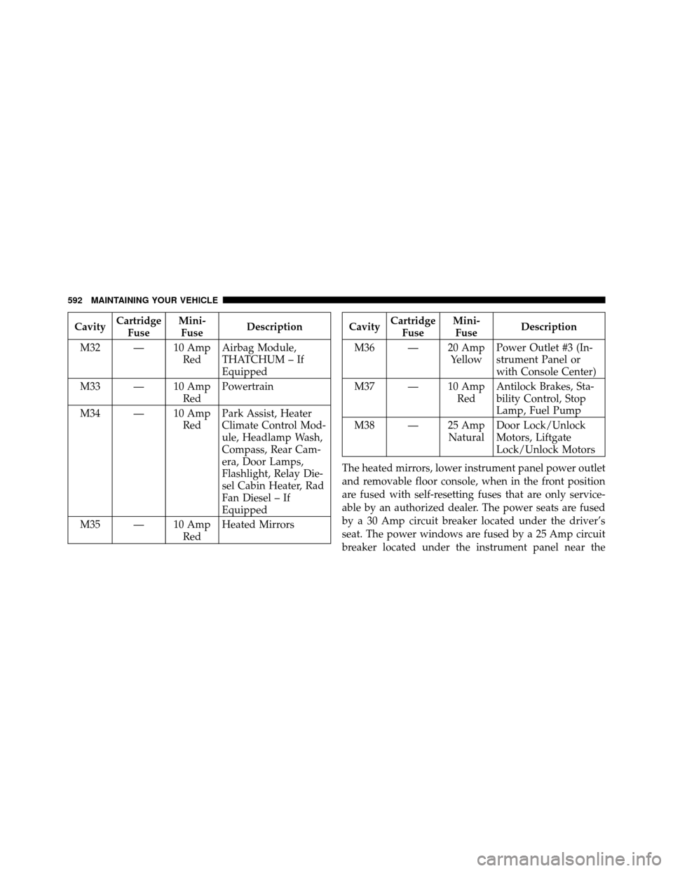
CavityCartridge
Fuse Mini-
Fuse Description
M32 — 10 Amp RedAirbag Module,
THATCHUM – If
Equipped
M33 — 10 Amp RedPowertrain
M34 — 10 Amp RedPark Assist, Heater
Climate Control Mod-
ule, Headlamp Wash,
Compass, Rear Cam-
era, Door Lamps,
Flashlight, Relay Die-
sel Cabin Heater, Rad
Fan Diesel – If
Equipped
M35 — 10 Amp RedHeated MirrorsCavity
Cartridge
Fuse Mini-
Fuse Description
M36 — 20 Amp YellowPower Outlet #3 (In-
strument Panel or
with Console Center)
M37 — 10 Amp RedAntilock Brakes, Sta-
bility Control, Stop
Lamp, Fuel Pump
M38 — 25 Amp NaturalDoor Lock/Unlock
Motors, Liftgate
Lock/Unlock Motors
The heated mirrors, lower instrument panel power outlet
and removable floor console, when in the front position
are fused with self-resetting fuses that are only service-
able by an authorized dealer. The power seats are fused
by a 30 Amp circuit breaker located under the driver’s
seat. The power windows are fused by a 25 Amp circuit
breaker located under the instrument panel near the
592 MAINTAINING YOUR VEHICLE
Page 595 of 652
steering column. If you experience temporary or perma-
nent loss of these systems, see your authorized dealer for
service.
VEHICLE STORAGE
If you are leaving your vehicle dormant for more than
21 days, you may want to take steps to protect your
battery. You may do the following:
•Remove the 20 Amp mini-fuse in the Totally Inte-
grated Power Module (TIPM) labeled Ignition-Off
Draw (IOD).
•Or, disconnect the negative cable from the battery.
•Anytime you store your vehicle, or keep it out of
service for two weeks or more, run the air conditioning
system at idle for about five minutes in the fresh air
and high blower setting. This will ensure adequate
system lubrication to minimize the possibility of com-
pressor damage when the system is started again.
REPLACEMENT BULBS
LIGHT BULBS – InteriorBulb Number
Center & Rear Dome Lamp ................. 578
Center & Rear Reading Lamps ............... 578
Front Door Courtesy Lamp .................. 578
Front Header Reading Lamps – If Equipped ..... 578
Instrument Cluster Lamps .................PC74
Liftgate Lamp(s) ......................... 578
Overhead Console Reading Lamps ..........PC579
Removable Console Lamp – If Equipped ........ 194
Visor Vanity Lamps .................... 6501966
NOTE: For lighted switches, see your authorized dealer
for replacement instructions.
All of the interior bulbs are glass wedge base or glass
cartridge types. Aluminum base bulbs are not approved
and should not be used for replacement.
7
MAINTAINING YOUR VEHICLE 593
Page 596 of 652
LIGHT BULBS – ExteriorBulb Number
Headlamp – (Low and High Beam Halogen) ..... H11
Headlamp (HID – If Equipped) Low Beam ...... D1S
Fog Lamp – If Equipped ................... H11
Front Side Marker ...................... W5W
Front Park/Turn Signal Lamp .....PY27/7W or 3757A
Rear Turn Signal Lamp .................. 3757A
Rear Tail, Stop, and Side Marker Lamp ........ LED
(Serviced at Authorized Dealer)
Backup ............................... 3157
Center High-Mounted Stop Lamp ............ LED
(Serviced at Authorized Dealer)
License ................................ 168
BULB REPLACEMENT
High Intensity Discharge Headlamps (HID) — If
Equipped
The headlamps are a type of high voltage discharge tube.
High voltage can remain in the circuit even with the headlamp switch off and the key removed.
Because of
this, you should not attempt to service a headlamp bulb
yourself. If a headlamp bulb fails, take your vehicle to
an authorized dealer for service.
WARNING!
A transient high voltage occurs at the bulb sockets of
High Intensity Discharge (HID) headlamps when the
headlamp switch is turned ON. It may cause serious
electrical shock or electrocution if not serviced prop-
erly. See your authorized dealer for service.
NOTE: On vehicles equipped with High Intensity Dis-
charge (HID) headlamps, when the headlamps are
turned on, there is a blue hue to the lamps. This dimin-
ishes and becomes more white after approximately
10 seconds, as the system charges.
594 MAINTAINING YOUR VEHICLE
Page 597 of 652
Quad Headlamps
1. Raise the hood to access the high or low beam bulbs at
the rear of the headlamp housing.
2. Release the two tabs on the side of the connector and
remove the connector from the bulb.
3. Twist the headlamp bulb and pull the bulb from the
headlamp housing.
4. Install the new headlamp bulb and twist until locked
into the headlamp housing.
CAUTION!
Do not touch the new bulb with your fingers. Oil
contamination will severely shorten bulb life. If the
bulb comes in contact with an oily surface, clean the
bulb with rubbing alcohol.5. Reconnect the wiring connector to the bulb.
Front Park/Turn Signal Lamp
1. Raise the hood to access the rear of the headlamp
housing.
2. Twist the turn signal socket and remove from the
headlamp housing, then pull the bulb out.
3. Push the new bulb into the socket and reinstall the
socket by twisting until locked into the headlamp
housing.
7
MAINTAINING YOUR VEHICLE 595
Page 598 of 652
Front Side Marker Lamp
1. Raise the hood to access the rear of the headlamp
housing.
NOTE:Access is somewhat limited. You may have to
remove the inner fender well or remove the headlamp
housing for bulb replacement.
2. Twist the socket and remove from the headlamp
housing, then pull the bulb out.
3. Push the new bulb into the socket and reinstall the
socket by twisting until locked into the headlamp
housing.
Fog Lamp
NOTE: Access to the fog lamp bulb is from the rear of
the fascia. On the left rear side of the fascia, remove the
push pin and lower the hinged access door on the air
dam.
1. From behind the bumper fascia, or the access panel on
the air dam, twist the bulb counterclockwise, and remove
bulb.
CAUTION!
Do not touch the new bulb with your fingers. Oil
contamination will severely shorten bulb life. If the
bulb comes in contact with an oily surface, clean the
bulb with rubbing alcohol.
2. Disconnect wire harness from the bulb.
596 MAINTAINING YOUR VEHICLE
Page 599 of 652
3. Reconnect the wiring harness to the new bulb and
reinstall the bulb by twisting clockwise.
Rear Tail, Stop, Turn Signal, Side Marker And
Backup Lamp
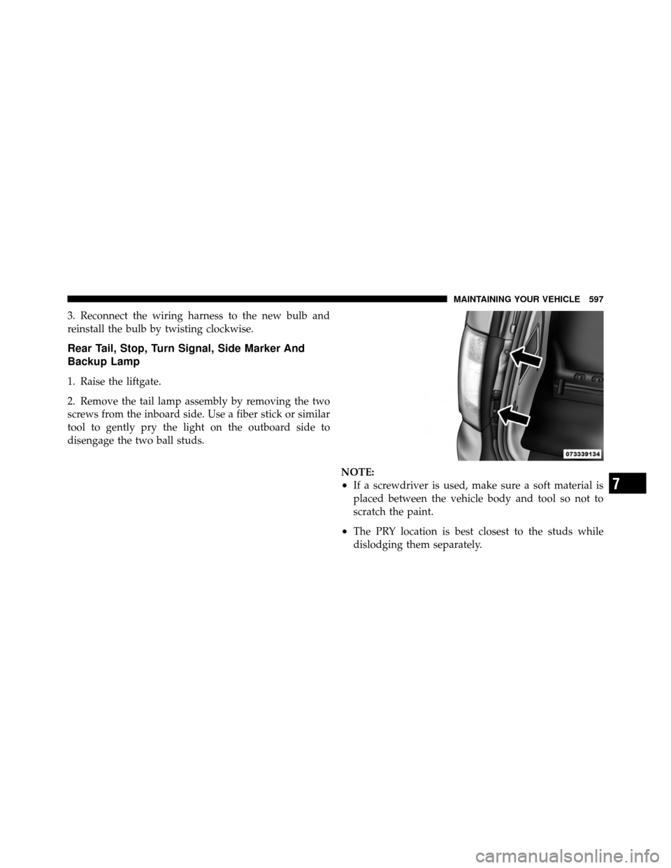
1. Raise the liftgate.
2. Remove the tail lamp assembly by removing the two
screws from the inboard side. Use a fiber stick or similar
tool to gently pry the light on the outboard side to
disengage the two ball studs.NOTE:
•If a screwdriver is used, make sure a soft material is
placed between the vehicle body and tool so not to
scratch the paint.
•The PRY location is best closest to the studs while
dislodging them separately.
7
MAINTAINING YOUR VEHICLE 597
Page 600 of 652
3. Twist the socket and remove it from the lamp assem-
bly.
4. Pull the bulb to remove it from the socket.
5. Replace the bulb, reinstall the socket, and reattach the
lamp assembly.
Center High-Mounted Stop Lamp (CHMSL)
The CHMSL uses LED lamps that are not serviceable
separately. The CHMSL must be replaced as an assembly,
see your authorized dealer.
License Lamp
The license plate lamp is located under the tailgate light
bar and above the license plate.
1. Using a small screwdriver, press inward the locking
tab on the outboard side of the lamp assembly and pull
down on the lamp assembly for removal.
2. Twist and remove the socket from the lamp assembly
and pull the bulb out to remove.
3. Push the bulb into the socket, twist the socket into the
lamp assembly and reinstall the lamp assembly into place
ensuring the locking tab is secure.
598 MAINTAINING YOUR VEHICLE