light CHRYSLER TOWN AND COUNTRY 2014 5.G User Guide
[x] Cancel search | Manufacturer: CHRYSLER, Model Year: 2014, Model line: TOWN AND COUNTRY, Model: CHRYSLER TOWN AND COUNTRY 2014 5.GPages: 148, PDF Size: 4.26 MB
Page 3 of 148
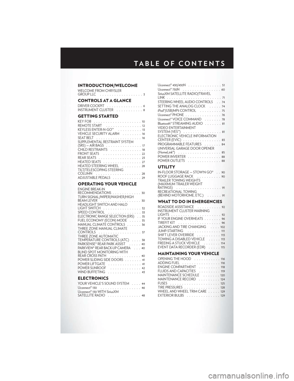
INTRODUCTION/WELCOME
WELCOME FROM CHRYSLER
GROUPLLC ..................3
CONTROLS AT A GLANCE
DRIVER COCKPIT...............6
INSTRUMENT CLUSTER ...........8
GETTING STARTED
KEYFOB ....................10
REMOTE START...............12
KEYLESS ENTER-N-GO™ ..........13
VEHICLE SECURITY ALARM ........16
SEATBELT ...................16
SUPPLEMENTAL RESTRAINT SYSTEM
(SRS)—AIRBAGS ...............17
CHILD RESTRAINTS .............18
FRONTSEATS ................22
REAR SEATS ..................23
HEATEDSEATS ................27
HEATED STEERING WHEEL ........28
TILT/TELESCOPING STEERING
COLUMN ...................28
ADJUSTABLE PEDALS ............29
OPERATING YOUR VEHICLE
ENGINE BREAK-IN
RECOMMENDATIONS............30
TURN SIGNAL/WIPER/WASHER/HIGH
BEAM LEVER .................30
HEADLIGHT SWITCH AND HALO
LIGHTSWITCH ................32
SPEED CONTROL ..............33
ELECTRONIC RANGE SELECTION (ERS) . . 35FUEL ECONOMY (ECON) MODE .....35
MANUAL CLIMATE CONTROLS ......36
THREE ZONE MANUAL CLIMATE
CONTROLS ..................37
THREE ZONE AUTOMATIC
TEMPERATURE CONTROLS (ATC) ....38
PARKSENSE® REAR PARK ASSIST .....40
PARKVIEW® REAR BACK-UP CAMERA...40
BLIND SPOT MONITORING WITH
REAR CROSS PATH .............40
POWER SLIDING SIDE DOORS .......41
POWERLIFTGATE ..............41
POWER SUNROOF .............42
WIND BUFFETING ..............43
ELECTRONICS
YOUR VEHICLE'S SOUND SYSTEM ....44
Uconnect® 130 . . ...............46
Uconnect® 130 WITH SiriusXM
SATELLITE RADIO ..............48 Uconnect® 430/430N
..............51
Uconnect® 730N ................60
SiriusXM SATELLITE RADIO/TRAVEL
LINK .......................71
STEERING WHEEL AUDIO CONTROLS..74
SETTING THE ANALOG CLOCK . . . . . 74
iPod®/USB/MP3 CONTROL .........75
Uconnect® PHONE ...............76
Uconnect® VOICE COMMAND .......78
Bluetooth® STREAMING AUDIO .......81
VIDEO ENTERTAINMENT
SYSTEM (VES™) ................81
ELECTRONIC VEHICLE INFORMATION
CENTER (EVIC) ................83
PROGRAMMABLE FEATURES .......84
UNIVERSAL GARAGE DOOR OPENER
(HomeLink®) . . ................85
POWER INVERTER ..............88
POWER OUTLETS ..............88
UTILITY
IN-FLOOR STORAGE — STOW'N GO® . . 90
ROOF LUGGAGE RACK ..........90
TRAILER TOWING WEIGHTS
(MAXIMUM TRAILER WEIGHT
RATINGS) ...................91
RECREATIONAL TOWING
(BEHIND MOTORHOME, ETC.) ......91
WHAT TO DO IN EMERGENCIES
ROADSIDE ASSISTANCE . .........92
INSTRUMENT CLUSTER WARNING
LIGHTS .....................92
IF YOUR ENGINE OVERHEATS . . . ....96
TIREFIT KIT ..................96
JACKING AND TIRE CHANGING ....102
JUMP-STARTING ..............111
SHIFT LEVER OVERRIDE ..........113
TOWING A DISABLED VEHICLE .....113
FREEING A STUCK VEHICLE . . . ....114
EVENT DATA RECORDER (EDR) . . . . . 115
MAINTAINING YOUR VEHICLE
OPENING THE HOOD ...........116
ADDING FUEL ................116
ENGINE COMPARTMENT .........118
FLUIDSANDCAPACITIES .........119
MAINTENANCE SCHEDULE .......120
MAINTENANCE RECORD .........124
FUSES .....................125
TIRE PRESSURES ...............128
WHEEL AND WHEEL TRIM CARE .....129
EXTERIOR BULBS ..............129
TABLE OF CONTENTS
Page 8 of 148
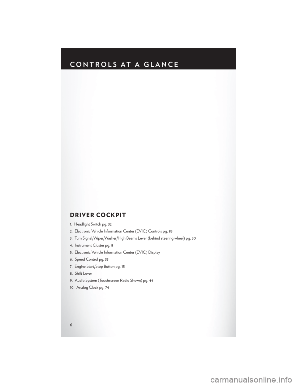
DRIVER COCKPIT
1. Headlight Switch pg. 32
2. Electronic Vehicle Information Center (EVIC) Controls pg. 83
3. Turn Signal/Wiper/Washer/High Beams Lever (behind steering wheel) pg. 30
4. Instrument Cluster pg. 8
5. Electronic Vehicle Information Center (EVIC) Display
6. Speed Control pg. 33
7. Engine Start/Stop Button pg. 15
8. Shift Lever
9. Audio System (Touchscreen Radio Shown) pg. 44
10. Analog Clock pg. 74
CONTROLS AT A GLANCE
6
Page 10 of 148
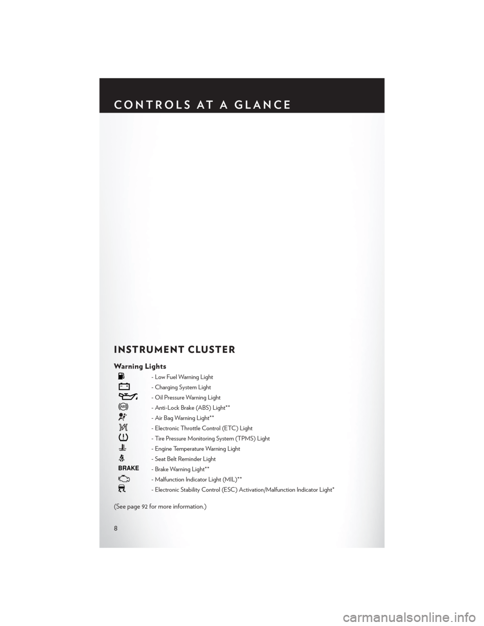
INSTRUMENT CLUSTER
Warning Lights
- Low Fuel Warning Light
- Charging System Light
- Oil Pressure Warning Light
- Anti-Lock Brake (ABS) Light**
- Air Bag Warning Light**
- Electronic Throttle Control (ETC) Light
- Tire Pressure Monitoring System (TPMS) Light
- Engine Temperature Warning Light
- Seat Belt Reminder Light
BRAKE- Brake Warning Light**
- Malfunction Indicator Light (MIL)**
- Electronic Stability Control (ESC) Activation/Malfunction Indicator Light*
(See page 92 for more information.)
CONTROLS AT A GLANCE
8
Page 11 of 148
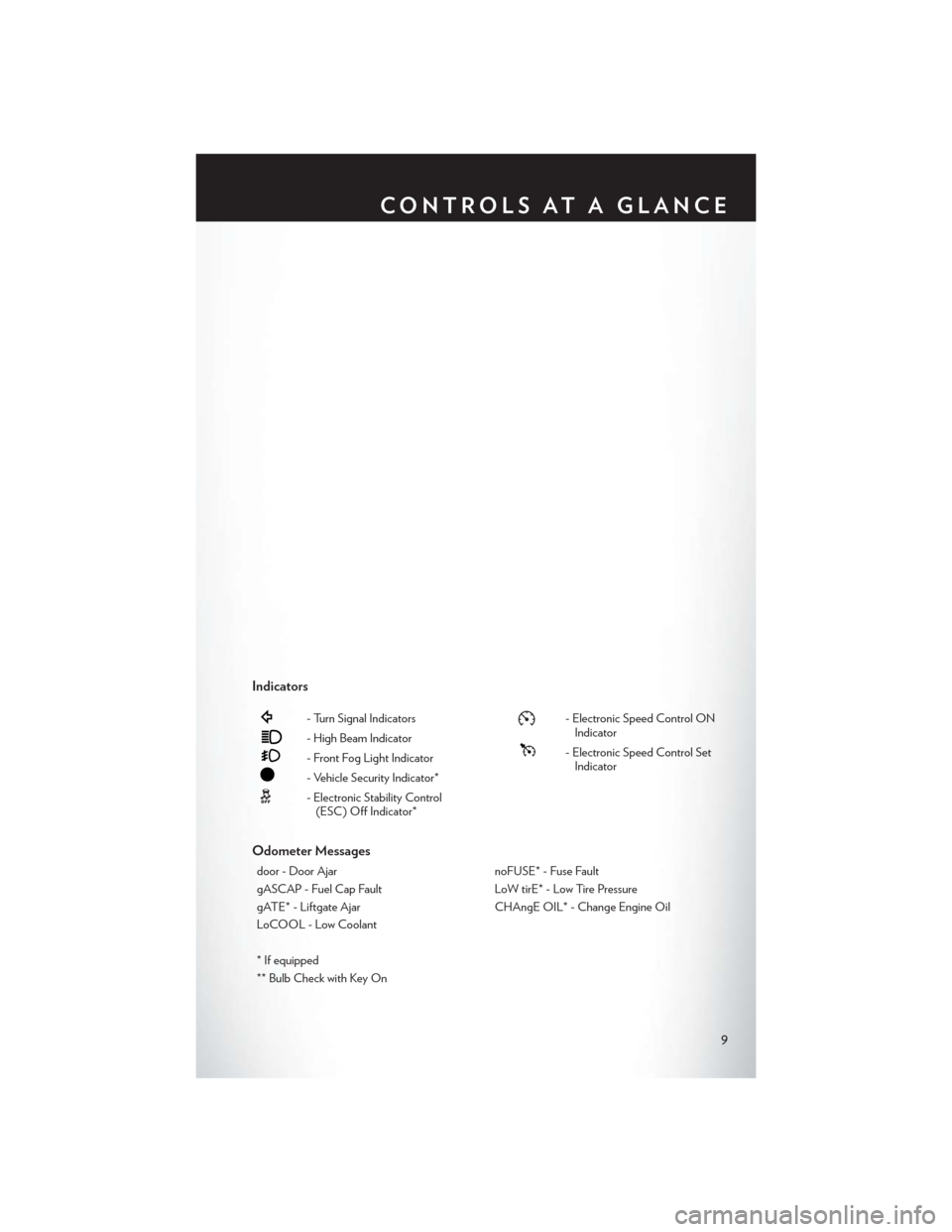
Indicators
- Turn Signal Indicators
- High Beam Indicator
- Front Fog Light Indicator
- Vehicle Security Indicator*
- Electronic Stability Control(ESC) Off Indicator*
- Electronic Speed Control ONIndicator
- Electronic Speed Control SetIndicator
Odometer Messages
door - Door Ajar noFUSE* - Fuse Fault
gASCAP - Fuel Cap Fault LoW tirE* - Low Tire Pressure
gATE* - Liftgate Ajar CHAngE OIL* - Change Engine Oil
LoCOOL - Low Coolant
* If equipped
** Bulb Check with Key On
CONTROLS AT A GLANCE
9
Page 19 of 148
A frayed or torn belt could rip apart in a collision and leave you with no protection. Inspect the belt
system periodically, checking for cuts, frays, or loose parts. Damaged parts must be replaced
immediately. Do not disassemble or modify the system. Seat belt assemblies must be replaced
after a collision if they have been damaged (bent retractor, torn webbing, etc.).
The seat belts for both front seating positions are equipped with pretensioning devices that are
designed to remove slack from the seat belt in the event of a collision.
A deployed pretensioner or a deployed air bag must be replaced immediately.
WARNING!
In a collision, you and your passengers can suffer much greater injuries if you are not buckled
up properly. You can strike the interior of your vehicle or other passengers, or you can be
thrown out of the vehicle. Always be sure you and others in your vehicle are buckled up
properly.
SUPPLEMENTAL RESTRAINT SYSTEM (SRS) —
AIR BAGS
• This vehicle has Advanced Front Air Bags for both the driver and front passenger as asupplement to the seat belt restraint systems. The driver's Advanced Front Air Bag is mounted
in the center of the steering wheel. The passenger's Advanced Front Air Bag is mounted in the
instrument panel, above the glove compartment. The words AIRBAG are embossed on the air
bag covers. In addition, the vehicle is equipped with a Supplemental Driver Side Knee Air Bag
mounted in the instrument panel below the steering column.
• The Advanced Front Air Bags have a multistage inflator design. This allows the air bag to have different rates of inflation based on several factors, including the severity and type of collision.
• This vehicle may be equipped with driver and/or front passenger seat track position sensors that may adjust the inflation rate of the Advanced Front Air Bags based upon seat position.
• This vehicle may be equipped with a driver and/or front passenger seat belt buckle switch that detects whether the driver or front passenger seat belt is fastened. The seat belt buckle switch
may adjust the inflation rate of the Advanced Front Air Bags.
• This vehicle may be equipped with Supplemental Side Air Bag Inflatable Curtains (SABIC) to protect the driver, front, and rear passengers sitting next to a window. The SABIC air bags are
located above the side windows and their covers are labeled: AIRBAG.
• If the Air Bag Warning Light
is not on during starting, stays on, or turns on while driving,
have the vehicle serviced by an authorized service center immediately.
• Refer to the Owner's Manual on the DVD for further details regarding the Supplemental Restraint System (SRS).
NOTE:
The Air Bag System is designed to be maintenance free.
GETTING STARTED
17
Page 33 of 148
•Vehicles equipped with Blind Spot Monitoring will produce a visual alert and may be programmed
to produce an audible alert when signaling a lane change; refer to your Owner’s Manual on the
DVD for operation.
Front Wipers
Intermittent, Low And High Operation
• Rotate the end of the lever to the first detent position for one of five intermittent settings, the second detent for low wiper operation and the third detent for high wiper operation.
Rain Sensing Wipers
• This feature senses moisture on the vehicle’s windshield and automatically activates the wipers for the driver when the switch is in the intermittent positions. Refer to Programmable Features
in Electronics for further details.
Mist
• Push the end of the lever inward to the first detent when a single wipe is desired.
NOTE:
The mist feature does not activate the washer pump; therefore, no washer fluid will be sprayed on
the windshield. The wash function must be activated in order to spray the windshield with washer
fluid.
Washer Operation
• Push the end of the lever inward to the second detent and hold for as long as spray is desired.
Rear Wiper
• Rotate the center portion of the lever forward to the first detent for rear wiper operation.
Rear Washer
• Rotate the center portion of the lever past the first detent to activate the rear washer.
High Beams
• Push the lever away from you to activate the high beams.
A high beam symbol will illuminate in the cluster to indicate the high beams are on.
NOTE:
For safe driving, turn off the high beams when oncoming traffic is present to prevent headlight
glare and as a courtesy to other motorists.
Flash To Pass
• Pull the lever toward you to activate the high beams. The high beams will remain on until the lever is released.
OPERATING YOUR VEHICLE
31
Page 34 of 148
HEADLIGHT SWITCH AND HALO LIGHT SWITCH
Automatic Headlights/Parking
Lights/Headlights
• Rotate the headlight switch, located on theinstrument panel to the left of the steering
wheel, to the first detent for parking lights
and to the second detent for head-
lights
.
• With the parking lights or low beam head- lights on, push the headlight switch once for
fog lights.
• Rotate the headlight switch to AUTO for Automatic Headlights.
• When set to AUTO, the system automati- cally turns the headlights on or off based on
ambient light levels.
Automatic High Beams
•The Automatic High Beams system provides increased forward lighting at night by automating
high beam control through the use of a digital camera mounted on the inside rearview mirror.
This camera detects vehicle specific light and automatically switches from high beams to low
beams until the approaching vehicle is out of view.
Instrument Panel Dimmer
• Rotate the dimmer control to the extreme bottom position to fully dim the instrument panel lights and prevent the interior lights from illuminating when a door is opened.
• Rotate the dimmer control up to increase the brightness of the instrument panel when the parking lights or headlights are on.
• Rotate the dimmer control up to the next detent position to fully brighten the odometer and radio when the parking lights or headlights are on.
• Rotate the dimmer control up to the last detent position to turn on the interior lighting.
• If your vehicle is equipped with a touchscreen, the dimming is programmable through the Uconnect® system. Refer to “Uconnect® Settings ” in “Understanding Your Instrument Panel”
in the Owner's Manual on the DVD for further details.
Overhead (Halo) Light
• To activate the Halo lights, rotate the Halo switch control upward or downward to increase ordecrease the lighting.
OPERATING YOUR VEHICLE
32
Page 37 of 148
ELECTRONIC RANGE SELECTION (ERS)
• Electronic Range Select (ERS) allows you tolimit the highest available transmission gear,
and can be activated during any driving con-
dition. When towing a trailer or operating
the vehicle in off-road conditions, using ERS
shift control will help you maximize both
performance and engine braking.
• To shift from DRIVE mode to ERS mode, move the shift lever to the left (-) once.
The current gear will be maintained as the
top gear. To disable ERS, simply press and
hold the shift lever to the right (+) until
“D” is displayed in the instrument cluster
odometer.
• Switching between ERS and DRIVE mode can be done at any vehicle speed.
• Refer to your Owner's Manual on the DVD for further details.
FUEL ECONOMY (ECON) MODE
• The Fuel Economy (ECON) mode can improve the vehicle’s overall fuel economy duringnormal driving conditions.
• Press the ECON switch in the center stack of the instrument panel and a green light will indicate the ECON mode is engaged.
OPERATING YOUR VEHICLE
35
Page 42 of 148
PARKSENSE® REAR PARK ASSIST
• If an object is detected behind the rear bumper while the vehicle is in REVERSE, a warning willdisplay in the instrument cluster and a tone will sound, (closer the object the faster the tone)
that changes speed depending on the distance of the object from the bumper, will sound.
• When the Instrument Cluster reads either “Clean Sensor” or “Blinded”, clean off the bumper sensors to see if the condition is corrected.
PARKVIEW® REAR BACK-UP CAMERA
You can see an on-screen image of the rear of your vehicle whenever the shift lever is put into
REVERSE. The ParkView® Rear Back-Up Camera image will be displayed on the radio display
screen, located on the center stack of the instrument panel.
If the radio display screen appears foggy, clean the camera lens located on the liftgate.
Refer to your Owner's Manual on the DVD for further details.
WARNING!
Drivers must be careful when backing up; even when using the ParkView® Rear Back-Up
Camera. Always check carefully behind your vehicle, and be sure to check for pedestrians,
animals, other vehicles, obstructions, or blind spots before backing up. You must continue to
pay attention while backing up. Failure to do so can result in serious injury or death.
BLIND SPOT MONITORING WITH REAR CROSS
PAT H
• The Blind Spot Monitoring (BSM) system uses two radar-based sensors, located inside therear bumper fascia, to detect Highway licensable vehicles (automobiles, trucks, motorcycles
etc.) that enter the blind spot zones from the rear/front/side of the vehicle.
• The Blind Spot Monitoring (BSM) system warning light, located in the outside mirrors, will illuminate if a vehicle moves into a blind spot zone.
• The BSM system can also be configured to sound an audible (chime) alert and mute the radio to notify you of objects that have entered the detection zones.
• Refer to your Owner's Manual on the DVD for further details.
OPERATING YOUR VEHICLE
40
Page 87 of 148
Sound Horn With Lock
To turn the horn chirp on or off when the doors are locked:
• Push the LOCK button and PANIC button at the same time for at least four seconds, but nolonger than 10 seconds.
• Release both buttons at the same time.
Flashing Lights With Lock
The turn signal lights flash when the doors are locked, which can be turned on or off. To turn this
feature on or off:
• Push and hold the UNLOCK button and the LOCK button at the same time for at least four seconds, but no longer than 10 seconds.
• Release both buttons at the same time.
UNIVERSAL GARAGE DOOR OPENER
(HomeLink®)
• HomeLink® replaces up to three hand-held transmitters that operate devices such as garage door openers, motorized gates, lighting or home security systems. The HomeLink® unit is
powered by your vehicles 12 Volt battery.
• The HomeLink® buttons that are located in the overhead console or sunvisor designate the three different HomeLink® channels.
• The HomeLink® indicator is located above the center button.
Before You Begin Programming
HomeLink®
Ensure that your vehicle is parked outside of
the garage before you begin programming.
For efficient programming and accurate trans-
mission of the radio-frequency signal, it is recom-
mended that a new battery be placed in the
hand-held transmitter of the device that is being
programmed to the HomeLink® system.
Erase all channels before you begin program-
ming. To erase the channels, place the ignition switch into the ON/RUN position, then press and
hold the two outside HomeLink® buttons (I and III) for up to 20 seconds or until the red indicator
flashes.
NOTE:
Erasing all channels should only be performed when programming HomeLink® for the first time.
Do not erase channels when programming additional buttons.
If you have any problems, or require assistance, please call toll-free 1-800-355-3515 or, on the
Internet at www.HomeLink.com for information or assistance.
ELECTRONICS
85