lug CHRYSLER TOWN AND COUNTRY 2015 5.G Owners Manual
[x] Cancel search | Manufacturer: CHRYSLER, Model Year: 2015, Model line: TOWN AND COUNTRY, Model: CHRYSLER TOWN AND COUNTRY 2015 5.GPages: 726, PDF Size: 20.14 MB
Page 95 of 726

SABICs may help reduce the risk of head injury to front
and rear seat outboard occupants. SABICs may reduce
the risk of injuries in certain side impact and vehicle
rollover events, in addition to the injury reduction poten-
tial provided by the seat belts and body structure.
The SABICs deploy downward, covering the side win-
dows. An inflating SABIC pushes the outside edge of the
trim out of the way and covers the window. The SABICs
inflate with enough force to injure you if you are not
belted and seated properly, or if items are positioned in
the area where the SABICs inflate. Children are at an
even greater risk of injury from a deploying air bag.
The SABICs may help reduce the risk of partial or
complete ejection of vehicle occupants through side
windows in certain rollover or side impact events.
WARNING!
•Your vehicle is equipped with left and right
Supplemental Side Air Bag Inflatable Curtains
(SABICs). Do not stack luggage or other cargo up
high enough to block the deployment of the
SABICs. The trim covering above the side win-
dows where the SABIC and its deployment path
are located should remain free from any obstruc-
tions.
•Your vehicle is equipped with SABICs. In order for
the SABICs to work as intended, do not install any
accessory items in your vehicle which could alter
the roof. Do not add an aftermarket sunroof to your
vehicle. Do not add roof racks that require perma-
nent attachments (bolts or screws) for installation
on the vehicle roof. Do not drill into the roof of the
vehicle for any reason.
2
THINGS TO KNOW BEFORE STARTING YOUR VEHICLE 93
Page 141 of 726

!LOAD LEVELING SYSTEM — IF EQUIPPED . .307
!ROOF LUGGAGE RACK — IF EQUIPPED . . . .307
▫Deploying The Crossbars................308
!SUN SCREENS — IF EQUIPPED............313
3
UNDERSTANDING THE FEATURES OF YOUR VEHICLE 139
Page 276 of 726

Canadian/Gate Operator Programming
For programming transmitters in Canada/United States
that require the transmitter signals to “time-out” after
several seconds of transmission.
Canadian radio frequency laws require transmitter sig-
nals to time-out (or quit) after several seconds of trans-
mission – which may not be long enough for HomeLink®
to pick up the signal during programming. Similar to this
Canadian law, some U.S. gate operators are designed to
time-out in the same manner.
It may be helpful to unplug the device during the cycling
process to prevent possible overheating of the garage
door or gate motor.
1. Cycle the ignition to the ON/RUN position.
2. Place the hand-held transmitter 1 to 3 inches (3 to
8 cm) away from the HomeLink® button you wish to
program while keeping the HomeLink® indicator
light in view.
3. Continue to push and hold the HomeLink® button,
while you push and release (“cycle”) your hand-held
transmitter every two seconds until HomeLink® has
successfully accepted the frequency signal. The indi-
cator light will flash slowly and then rapidly when
fully trained.
4. Watch for the HomeLink® indicator to change flash
rates. When it changes, it is programmed. It may take
up to 30 seconds or longer in rare cases. The garage
door may open and close while you are programming.
5. Push and hold the programmed HomeLink® button
and observe the indicator light.
274 UNDERSTANDING THE FEATURES OF YOUR VEHICLE
Page 277 of 726

•If the indicator light stays on constantly, program-
ming is complete and the garage door/device should
activate when the HomeLink® button is pushed.
•To program the two remaining HomeLink® buttons,
repeat each step for each remaining button. DO NOT
erase the channels.
If you unplugged the garage door opener/device for
programming, plug it back in at this time.
Reprogramming A Single HomeLink® Button
(Canadian/Gate Operator)
To reprogram a channel that has been previously trained,
follow these steps:
1. Cycle the ignition to the ON/RUN position.
2. Push and hold the desired HomeLink® button until
the indicator light begins to flash after 20 seconds.Do
not release the button.
3.Without releasing the buttonproceed with
“Canadian/Gate Operator Programming” step 2 and
follow all remaining steps.
Using HomeLink®
To operate, push and release the programmed
HomeLink® button. Activation will now occur for the
programmed device (i.e., garage door opener, gate opera-
tor, security system, entry door lock, home/office light-
ing, etc.,). The hand-held transmitter of the device may
also be used at any time.
Security
It is advised to erase all channels before you sell or turn
in your vehicle.
To do this, push and hold the two outside buttons for 20
seconds until the red indicator flashes. Note that all
channels will be erased. Individual channels cannot be
erased.
3
UNDERSTANDING THE FEATURES OF YOUR VEHICLE 275
Page 278 of 726
The HomeLink® Universal Transceiver is disabled when
the Vehicle Security Alarm is active.
Troubleshooting Tips
If you are having trouble programming HomeLink®,
here are some of the most common solutions:
•Replace the battery in the original hand-held transmit-
ter.
•Push the LEARN button on the Garage Door Opener
to complete the training for a Rolling Code.
•Did you unplug the device for programming and
remember to plug it back in?
If you have any problems, or require assistance, please
call toll-free 1-800-355-3515 or, on the Internet at
HomeLink.com for information or assistance.
WARNING!
Vehicle exhaust contains carbon monoxide, a danger-
ous gas. Do not run your vehicle in the garage while
programming the transceiver. Exhaust gas can cause
serious injury or death.
WARNING!
Your motorized door or gate will open and close
while you are programming the universal trans-
ceiver. Do not program the transceiver if people, pets
or other objects are in the path of the door or gate.
Only use this transceiver with a garage door opener
that has a “stop and reverse” feature as required by
Federal safety standards. This includes most garage
door opener models manufactured after 1982. Do not
(Continued)
276 UNDERSTANDING THE FEATURES OF YOUR VEHICLE
Page 284 of 726
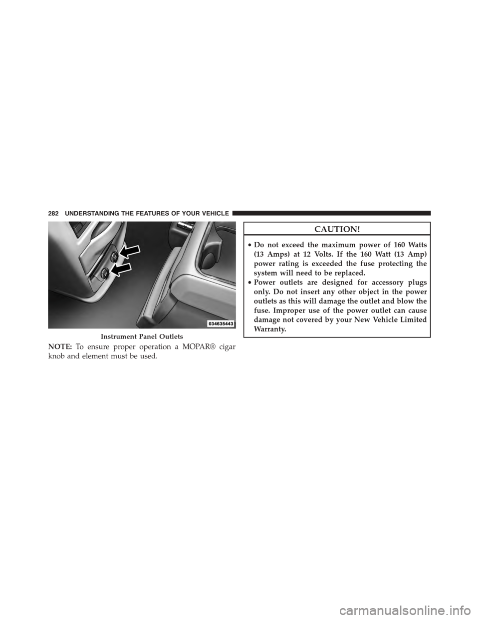
NOTE:To ensure proper operation a MOPAR® cigar
knob and element must be used.
CAUTION!
•Do not exceed the maximum power of 160 Watts
(13 Amps) at 12 Volts. If the 160 Watt (13 Amp)
power rating is exceeded the fuse protecting the
system will need to be replaced.
•Power outlets are designed for accessory plugs
only. Do not insert any other object in the power
outlets as this will damage the outlet and blow the
fuse. Improper use of the power outlet can cause
damage not covered by your New Vehicle Limited
Warranty.Instrument Panel Outlets
282 UNDERSTANDING THE FEATURES OF YOUR VEHICLE
Page 286 of 726
The outlet in the rear quarter panel near the liftgate and
the upper outlet in the instrument panel are both con-
trolled by the ignition switch. Each of these outlets can
support 160 Watts (13 Amps). Do not exceed 160 Watts
(13 Amps) for each of these outlets.
The power outlets include tethered caps, labeled with a
key or battery symbol indicating the power source. The
power outlet, located on the lower instrument panel, is
powered directly from the battery. Items plugged into
this power outlet may discharge the battery and/or
prevent the engine from starting.
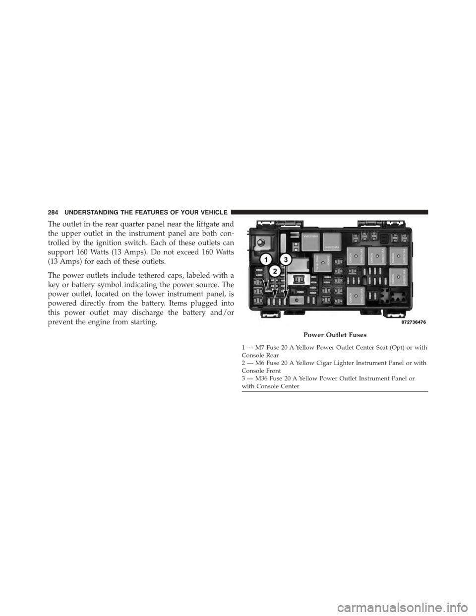
Power Outlet Fuses
1 — M7 Fuse 20 A Yellow Power Outlet Center Seat (Opt) or withConsole Rear2 — M6 Fuse 20 A Yellow Cigar Lighter Instrument Panel or withConsole Front3 — M36 Fuse 20 A Yellow Power Outlet Instrument Panel orwith Console Center
284 UNDERSTANDING THE FEATURES OF YOUR VEHICLE
Page 287 of 726
WARNING!
To avoid serious injury or death:
•Only devices designed for use in this type of outlet
should be inserted into any 12 Volt outlet.
•Do not touch with wet hands.
•Close the lid when not in use and while driving the
vehicle.
•If this outlet is mishandled, it may cause an electric
shock and failure.
CAUTION!
•Many accessories that can be plugged in draw
power from the vehicle’s battery, even when not in
use (i.e., cellular phones, etc.). Eventually, if
plugged in long enough, the vehicle’s battery will
discharge sufficiently to degrade battery life and/or
prevent the engine from starting.
•Accessories that draw higher power (i.e., coolers,
vacuum cleaners, lights, etc.), will degrade the
battery even more quickly. Only use these intermit-
tently and with greater caution.
•After the use of high power draw accessories, or
long periods of the vehicle not being started (with
accessories still plugged in), the vehicle must be
driven a sufficient length of time to allow the
alternator to recharge the vehicle’s battery.
(Continued)
3
UNDERSTANDING THE FEATURES OF YOUR VEHICLE 285
Page 288 of 726
CAUTION!(Continued)
•Power outlets are designed for accessory plugs
only. Do not hang any type of accessory or acces-
sory bracket from the plug. Improper use of the
power outlet can cause damage.
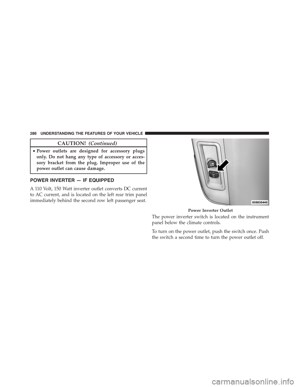
POWER INVERTER — IF EQUIPPED
A 110 Volt, 150 Watt inverter outlet converts DC current
to AC current, and is located on the left rear trim panel
immediately behind the second row left passenger seat.
The power inverter switch is located on the instrument
panel below the climate controls.
To turn on the power outlet, push the switch once. Push
the switch a second time to turn the power outlet off.
Power Inverter Outlet
286 UNDERSTANDING THE FEATURES OF YOUR VEHICLE
Page 301 of 726
CONSOLE FEATURES
There are three consoles available: Basic, Premium and
Super.
WARNING!
Do not operate this vehicle with a console compart-
ment lid in the open position. Driving with the
console compartment lid open may result in injury in
a collision.
Basic Console
Basic Console features consist of the following:
•The basic console profile allows vehicle occupants to
easily pass through the first row to the second.
•Four cupholders accept up to extra large size beverage
cups or 20 oz (.6 L) plastic bottles. Cupholders are
dishwasher safe for cleaning.
•The cupholders are removable to access a large storage
bin.
•The basic console is removable from the vehicle for
additional floor space by removing the cap and clip at
the console base.
To Remove The Basic Floor Console
1. Remove the front anchor cup plug and clip.
2. Slide the console base forward while lifting slightly to
clear the rear load floor hook.
3. Remove the console.
To Reinstall The Basic Floor Console
1. Position the console at a slight angle (front slightly
higher than the rear).
2. Slide the console rearward into the floor bracket/
hook.
3
UNDERSTANDING THE FEATURES OF YOUR VEHICLE 299