ECU CHRYSLER TOWN AND COUNTRY 2015 5.G Owner's Manual
[x] Cancel search | Manufacturer: CHRYSLER, Model Year: 2015, Model line: TOWN AND COUNTRY, Model: CHRYSLER TOWN AND COUNTRY 2015 5.GPages: 164, PDF Size: 22.47 MB
Page 70 of 164
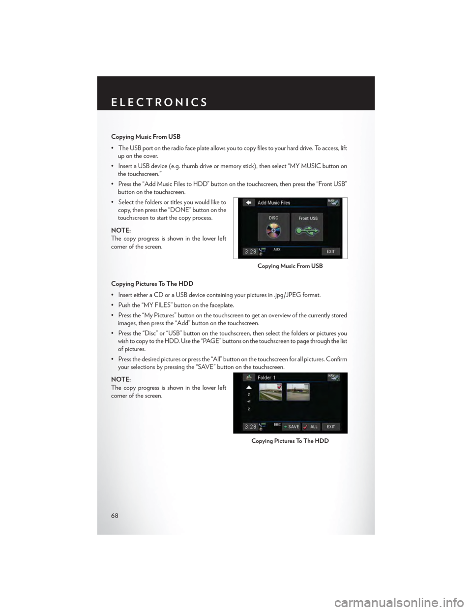
Copying Music From USB
•TheUSBportontheradiofaceplateallowsyoutocopyfilestoyourharddrive.Toaccess,lift
up on the cover.
•InsertaUSBdevice(e.g.thumbdriveormemorystick),thenselect“MYMUSICbuttonon
the touchscreen.”
•Pressthe“AddMusicFilestoHDD”buttononthetouchscreen,thenpressthe“FrontUSB”
button on the touchscreen.
•Selectthefoldersortitlesyouwouldliketo
copy, then press the “DONE” button on the
touchscreen to start the copy process.
NOTE:
The copy progress is shown in the lower left
corner of the screen.
Copying Pictures To The HDD
•InserteitheraCDoraUSBdevicecontainingyourpicturesin.jpg/JPEGformat.
• Push the “MY FILES” button on the faceplate.
•Pressthe“MyPictures”buttononthetouchscreentogetanoverviewofthecurrentlystored
images, then press the “Add” button on the touchscreen.
•Pressthe“Disc”or“USB”buttononthetouchscreen,thenselectthefoldersorpicturesyou
wish to copy to the HDD. Use the “PAGE” buttons on the touchscreen to page through the list
of pictures.
• Press the desired pictures or press the “All” button on the touchscreen for all pictures. Confirm
your selections by pressing the “SAVE” button on the touchscreen.
NOTE:
The copy progress is shown in the lower left
corner of the screen.
Copying Music From USB
Copying Pictures To The HDD
ELECTRONICS
68
Page 78 of 164
Replay
•WhileyouareinSATmode,youcanreplay44minutesofthecurrentSiriusXMchannel(when
the channel is changed, this audio buffer is erased). Push the REPLAY button to listen to the
stored audio.
•Youcanpresstheon-screencontrolstopauseandrewindaudioplayback,presstheSCAN
button to preview each of the tracks stored in the buffer, or select a track from the list.
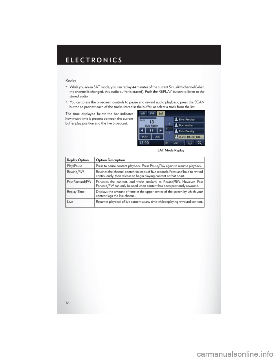
The time displayed below the bar indicates
how much time is present between the current
buffer play position and the live broadcast.
Replay Option Option Description
Play/Pause Press to pause content playback. Press Pause/Play again to resume playback.
Rewind/RW Rewinds the channel content in steps of five seconds. Press and hold to rewindcontinuously, then release to begin playing content at that point.
Fast For ward/FW For wards the content, and works similarly to Rewind/RW. However, FastForward/FW can only be used when content has been previously rewound.
Replay Time Displays the amount of time in the upper center of the screen by which yourcontent lags the live channel.
Live Resumes playback of live content at any time while replaying rewound content.
SAT Mode Replay
ELECTRONICS
76
Page 90 of 164
PROGRAMMABLE FEATURES
Electronic Vehicle Information Center (EVIC ) — If Equipped
Personal Settings allows you to set and recall features when the transmission is in PARK. If the
transmission is out of PARK or the vehicle begins moving, a warning message SYSTEM SETUP
NOT AVAILABLE VEHICLE NOT IN PARK displays when you try to select “System Setup”
from the main menu.
The EVIC can be used to program the following Personal Settings. Push the RIGHT arrow
buttonuntil Personal Settings displays, then push the DOWN buttonto scroll through
the settings. Push the RIGHT arrow buttonto change the setting.
• Select Language• Key-Off Power Delay
•Nav-TurnByTurn•IlluminatedApproach
• Auto Lock Doors• Hill Start Assist
• Auto Unlock Doors• Flashers with Sliding Door
•RemoteUnlockSequence•CalibrateCompass
•RemoteStartComfortSys.•CompassVariance
• Horn with Remote Lock• Park Assist - If Equipped
• Flash Lamps With Lock• Automatic High Beams - If Equipped
• Headlamp Off Delay• Keyless Enter-N-Go - If Equipped
• Headlamps With Wipers• RKE Linked To Memory - If Equipped
Key Fob Programmable Features
The following features may also be programmed by using the Key Fob transmitter or the ignition
switch and driver's door lock switch.
NOTE:
Pushing the LOCK button while you are inside the vehicle will activate the Vehicle Security
Alarm. Opening a door with the Vehicle Security Alarm activated will cause the alarm to sound.
Push the UNLOCK button to deactivate the Vehicle Security Alarm.
Unlock On First Press
To u n l o c k e i t h e r t h e d r i v e r ' s s i d e , o r a l l d o o r s , o n t h e f i r s t p u s h o f t h e U N L O C K b u t t o n :
• Push and hold the LOCK button for at least four seconds, but no longer than 10 seconds.
Then, push and hold the UNLOCK button while still holding the LOCK button.
• Release both buttons at the same time.
Auto Unlock Doors On Exit
To h a v e a l l o f t h e v e h i c l e d o o r s u n l o c k w h e n a n y d o o r i s o p e n e d :
•Enteryourvehicleandcloseallthedoors,andfastenyourseatbelt.
•CycletheignitionswitchbetweentheLOCKandONpositionfourtimes,endinginthe
LOCK position (do not start the engine).
ELECTRONICS
88
Page 91 of 164
• Push the power door UNLOCK switch to unlock the doors. A single chime will indicate that
programming is complete.
Sound Horn With Lock
To turn the horn chirp on or off when the doors are locked:
• Push the LOCK button and PANIC button at the same time for at least four seconds, but no
longer than 10 seconds.
• Release both buttons at the same time.
Flashing Lights With Lock
The turn signal lights flash when the doors are locked, which can be turned on or off. To turn this
feature on or off:
• Push and hold the UNLOCK button and the LOCK button at the same time for at least four
seconds, but no longer than 10 seconds.
• Release both buttons at the same time.
UNIVERSAL GARAGE DOOR OPENER
(HomeLink®)
HomeLink® replaces up to three hand-held transmitters that operate devices such as garage door
openers, motorized gates, lighting or home security systems. The HomeLink® unit is powered by
your vehicles 12 Volt battery.
The HomeLink® buttons that are located in the overhead console or sunvisor designate the three
different HomeLink® channels.
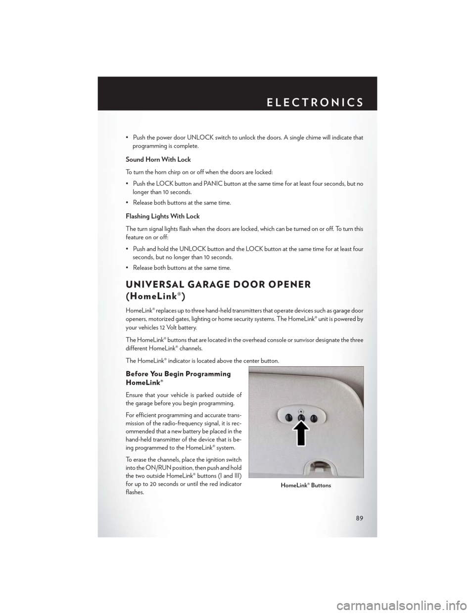
The HomeLink® indicator is located above the center button.
Before You Begin Programming
HomeLink®
Ensure that your vehicle is parked outside of
the garage before you begin programming.
For efficient programming and accurate trans-
mission of the radio-frequency signal, it is rec-
ommended that a new battery be placed in the
hand-held transmitter of the device that is be-
ing programmed to the HomeLink® system.
To erase the channels, place the ignition switch
into the ON/RUN position, then push and hold
the two outside HomeLink® buttons (I and III)
for up to 20 seconds or until the red indicator
flashes.HomeLink® Buttons
ELECTRONICS
89
Page 93 of 164

Programming A Non-Rolling Code
NOTE:
For programming Garage Door Openers manufactured before 1995.
1. Turn the ignition switch to the ON/RUN position.
2. Place the hand-held transmitter 1 to 3 inches (3 to 8 cm) away from the HomeLink® button you
wish to program while keeping the HomeLink® indicator light in view.
3. Push and hold the HomeLink® button you want to program while you push and hold the
hand-held transmitter button.
4. Continue to hold both buttons and observe the indicator light. The HomeLink® indicator will
flash slowly and then rapidly after HomeLink® has received the frequency signal from the
hand-held transmitter. Release both buttons after the indicator light changes from slow to
rapid.
5. Push and hold the programmed HomeLink® button and observe the indicator light. If the
indicator light stays on constantly, programming is complete and the garage door (or device)
should activate when the HomeLink® button is pushed.
6. To program the two remaining HomeLink® buttons, repeat each step for each remaining
button. DO NOT erase the channels.
Using HomeLink®
To o p e r a t e , p u s h a n d r e l e a s e t h e p r o g r a m m e d H o m e L i n k ® b u t t o n . A c t i v a t i o n w i l l n o w o c c u r f o r
the programmed device (e.g., garage door opener, gate operator, security system, entry door
lock, home/office lighting, etc.). The hand-held transmitter of the device may also be used at any
time.
WARNING!
•Yourmotorizeddoororgatewillopenandclosewhileyouareprogrammingtheuniversal
transceiver. Do not program the transceiver if people or pets are in the path of the door
or gate.
•Donotrunyourvehicleinaclosedgarageorconfinedareawhileprogrammingthe
transceiver. Exhaust gas from your vehicle contains Carbon Monoxide (CO) which is
odorless and colorless. Carbon Monoxide is poisonous when inhaled and can cause you
and others to be severely injured or killed.
ELECTRONICS
91
Page 99 of 164

RECREATIONAL TOWING
(BEHIND MOTORHOME, ETC.)
Towing Condition Wheels OFF the GroundAll Models
Flat TowNONENOT ALLOWED
Dolly TowFrontOK
RearNOT ALLOWED
On TrailerALLOK
Recreational Towing — All Models
Recreational towing is allowed ONLY if the front wheels are OFF the ground. This may be
accomplished using a tow dolly or vehicle trailer. If using a tow dolly, follow this procedure:
1. Properly secure the dolly to the tow vehicle, following the dolly manufacturer's instructions.
2. Drive the front wheels onto the tow dolly.
3. Firmly apply the parking brake. Place the transmission in PARK.
4. Properly secure the front wheels to the dolly, following the dolly manufacturer's instructions.
5. Release the parking brake.
CAUTION!
•DONOTflattowthisvehicle.Damagetothedrivetrainwillresult.
•Towingthisvehicleinviolationoftheaboverequirementscancauseseveretransmission
damage. Damage from improper towing is not covered under the New Vehicle Limited
Warranty.
UTILITY
97
Page 104 of 164
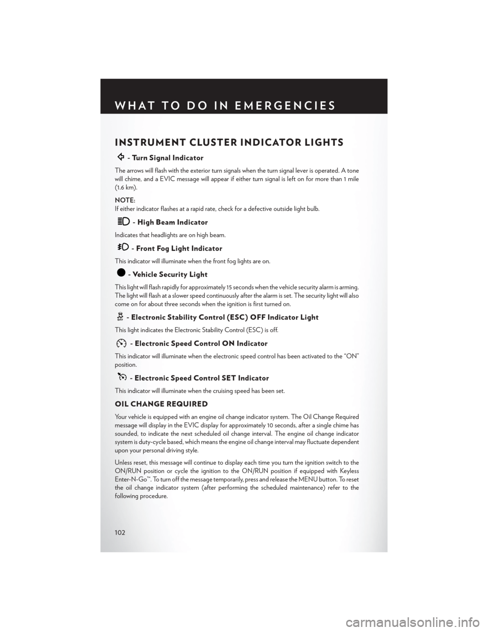
INSTRUMENT CLUSTER INDICATOR LIGHTS
-TurnSignalIndicator
The arrows will flash with the exterior turn signals when the turn signal lever is operated. A tone
will chime, and a EVIC message will appear if either turn signal is left on for more than 1 mile
(1.6 km).
NOTE:
If either indicator flashes at a rapid rate, check for a defective outside light bulb.
-HighBeamIndicator
Indicates that headlights are on high beam.
-FrontFogLightIndicator
This indicator will illuminate when the front fog lights are on.
-VehicleSecurityLight
This light will flash rapidly for approximately 15 seconds when the vehicle security alarm is arming.
The light will flash at a slower speed continuously after the alarm is set. The security light will also
come on for about three seconds when the ignition is first turned on.
-ElectronicStabilityControl(ESC)OFFIndicatorLight
This light indicates the Electronic Stability Control (ESC) is off.
-ElectronicSpeedControlONIndicator
This indicator will illuminate when the electronic speed control has been activated to the “ON”
position.
-ElectronicSpeedControlSETIndicator
This indicator will illuminate when the cruising speed has been set.
OIL CHANGE REQUIRED
Yo u r v e h i c l e i s e q u i p p e d w i t h a n e n g i n e o i l c h a n g e i n d i c a t o r s y s t e m . T h e O i l C h a n g e R e q u i r e d
message will display in the EVIC display for approximately 10 seconds, after a single chime has
sounded, to indicate the next scheduled oil change interval. The engine oil change indicator
system is duty-cycle based, which means the engine oil change interval may fluctuate dependent
upon your personal driving style.
Unless reset, this message will continue to display each time you turn the ignition switch to the
ON/RUN position or cycle the ignition to the ON/RUN position if equipped with Keyless
Enter-N-Go™. To turn off the message temporarily, press and release the MENU button. To reset
the oil change indicator system (after performing the scheduled maintenance) refer to the
following procedure.
WHAT TO DO IN EMERGENCIES
102
Page 119 of 164

Rear jack locations are between a pair of down-facing tabs on the sill flange of the vehicle
side body.
Front jack location is on the sill flange of the vehicle body and is located 6 in (150 mm) from
door edge.
NOTE:
In some situations the jack may need to be
placed on its side in order to be pushed under
the vehicle. Return the jack to its correct orien-
tation once it is under the vehicle.
3. Place the wrench on the jack screw and turn to the right until the jack head is properly engaged
in the described location.Do not raise the vehicle until you are sure the jack is securely
engaged.
4. Raise the vehicle by turning the jack screw to the right, using the swivel wrench. Raise the
vehicle only until the tire just clears the surface and enough clearance is obtained to install the
spare tire. Minimum tire lift provides maximum stability.
5. Remove the wheel lug nuts, for vehicles with wheel covers, remove the cover from the wheel
by hand. Do not pry the wheel cover off. Then pull the wheel off the hub.
Rear Jacking Location Engaged
Front Jacking Location Engaged
WHAT TO DO IN EMERGENCIES
117
Page 120 of 164
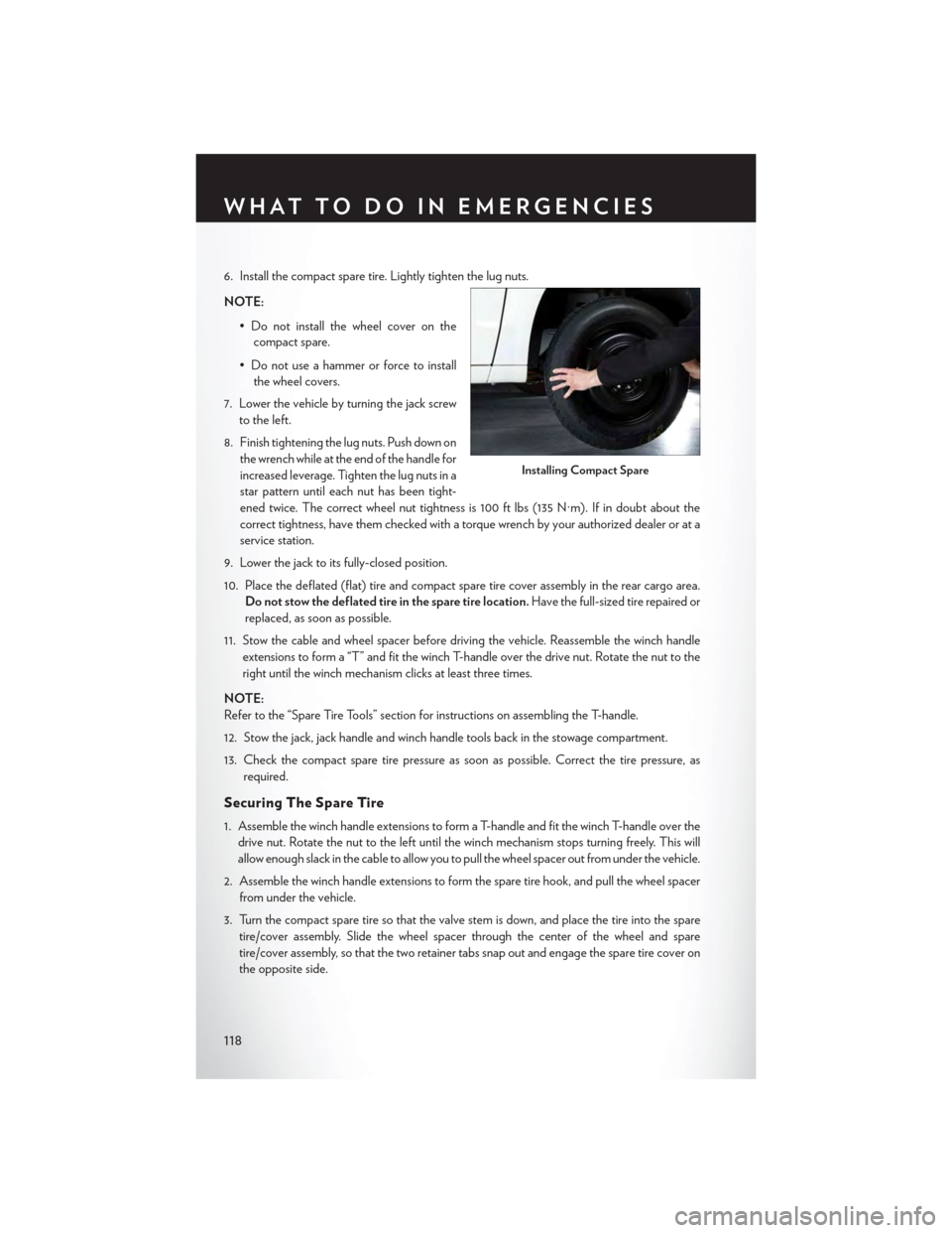
6. Install the compact spare tire. Lightly tighten the lug nuts.
NOTE:
•Donotinstallthewheelcoveronthe
compact spare.
• Do not use a hammer or force to install
the wheel covers.
7. Lower the vehicle by turning the jack screw
to the left.
8. Finish tightening the lug nuts. Push down on
the wrench while at the end of the handle for
increased leverage. Tighten the lug nuts in a
star pattern until each nut has been tight-
ened twice. The correct wheel nut tightness is 100 ft lbs (135 N·m). If in doubt about the
correct tightness, have them checked with a torque wrench by your authorized dealer or at a
service station.
9. Lower the jack to its fully-closed position.
10. Place the deflated (flat) tire and compact spare tire cover assembly in the rear cargo area.
Do not stow the deflated tire in the spare tire location.Have the full-sized tire repaired or
replaced, as soon as possible.
11. Stow the cable and wheel spacer before driving the vehicle. Reassemble the winch handle
extensions to form a “T” and fit the winch T-handle over the drive nut. Rotate the nut to the
right until the winch mechanism clicks at least three times.
NOTE:
Refer to the “Spare Tire Tools” section for instructions on assembling the T-handle.
12. Stow the jack, jack handle and winch handle tools back in the stowage compartment.
13. Check the compact spare tire pressure as soon as possible. Correct the tire pressure, as
required.
Securing The Spare Tire
1. Assemble the winch handle extensions to form a T-handle and fit the winch T-handle over the
drive nut. Rotate the nut to the left until the winch mechanism stops turning freely. This will
allow enough slack in the cable to allow you to pull the wheel spacer out from under the vehicle.
2. Assemble the winch handle extensions to form the spare tire hook, and pull the wheel spacer
from under the vehicle.
3. Turn the compact spare tire so that the valve stem is down, and place the tire into the spare
tire/cover assembly. Slide the wheel spacer through the center of the wheel and spare
tire/cover assembly, so that the two retainer tabs snap out and engage the spare tire cover on
the opposite side.
Installing Compact Spare
WHAT TO DO IN EMERGENCIES
118
Page 123 of 164
WARNING!
•Donotattempttochangeatireonthesideofthevehicleclosetomovingtraffic.Pullfar
enough off the road to avoid the danger of being hit when operating the jack or changing
the wheel.
•Beingunderajacked-upvehicleisdangerous.Thevehiclecouldslipoffthejackandfallon
you. You could be crushed. Never put any part of your body under a vehicle that is on a
jack. If you need to get under a raised vehicle, take it to a service center where it can be
raised on a lift.
•Neverstartorruntheenginewhilethevehicleisonajack.
• The jack is designed to be used as a tool for changing tires only. The jack should not be
used to lift the vehicle for service purposes. The vehicle should be jacked on a firm level
surface only. Avoid ice or slippery areas.
•Carefullyfollowthesetirechangingwarningstohelppreventpersonalinjuryordamageto
your vehicle:
•Alwaysparkonafirm,levelsurfaceasfarfromtheedgeoftheroadwayaspossiblebefore
raising the vehicle.
• Turn on the Hazard Warning flasher.
• Block the wheel diagonally opposite the wheel to be raised.
•SettheparkingbrakefirmlyandsetanautomatictransmissioninPARK;amanual
transmission in REVERSE.
•Donotletanyonesitinthevehiclewhenitisonajack.
•Donotgetunderthevehiclewhenitisonajack.
•Onlyusethejackinthepositionsindicatedandforliftingthisvehicleduringatirechange.
•Ifworkingonorneararoadway,beextremelycarefulofmotortraffic.
•Toassurethatsparetires,flatorinflated,aresecurelystowed,sparesmustbestowedwith
the valve stem facing the ground.
•Raisingthevehiclehigherthannecessarycanmakethevehiclelessstable.Itcouldslipoff
the jack and hurt someone near it. Raise the vehicle only enough to remove the tire.
•Toavoidtheriskofforcingthevehicleoffthejack,donottightenthewheelnutsfullyuntil
the vehicle has been lowered. Failure to follow this warning may result in personal injury.
•Aloosetireorjackthrownforwardinacollisionorhardstopcouldendangertheoccupants
of the vehicle. Always stow the jack parts andthe spare tire in the places provided. Have
the deflated (flat) tire repaired or replaced immediately.
•Verifythatbothretainertabsofthewheelspacerhavebeenproperlyextendedthrough
the center of the wheel and spare tire/cover assembly. Failure to properly engage both
retainer tabs could result in loss of the spare tire and cover assembly, which will cause
vehicle damage and may cause loss of vehicle control.
WHAT TO DO IN EMERGENCIES
121