ESC CHRYSLER TOWN AND COUNTRY 2015 5.G Owner's Manual
[x] Cancel search | Manufacturer: CHRYSLER, Model Year: 2015, Model line: TOWN AND COUNTRY, Model: CHRYSLER TOWN AND COUNTRY 2015 5.GPages: 164, PDF Size: 22.47 MB
Page 100 of 164

ROADSIDE ASSISTANCE
Dial toll-free 1-800-521-2779 for U.S. Residents or 1-800-363-4869 for Canadian Residents.
•Provideyourname,vehicleidentificationnumber,licenseplatenumber,andyourlocation,
including the telephone number from which you are calling.
• Briefly describe the nature of the problem and answer a few simple questions.
•Youwillbegiventhenameoftheserviceproviderandanestimatedtimeofarrival.Ifyoufeel
you are in an “unsafe situation”, please let us know. With your consent, we will contact local
police or safety authorities.
INSTRUMENT CLUSTER WARNING LIGHTS
-LowFuelWarningLight
This warning light indicates when the fuel level reaches approximately 2.0 gal (7.8 L), this light will
turn on and a single chime will sound.
-ChargingSystemLight
This light shows the status of the electrical charging system. If the charging system light remains
on, it means that the vehicle is experiencing a problem with the charging system.
We r e c o m m e n d y o u d o n o t c o n t i n u e d r i v i n g i f t h e c h a r g i n g s y s t e m l i g h t i s o n . H a v e t h e v e h i c l e
serviced immediately.
-OilPressureWarningLight
This light indicates low engine oil pressure. If the light turns on while driving, stop the vehicle and
shut off the engine as soon as possible. A chime will sound when this light turns on.
We r e c o m m e n d y o u d o n o t o p e r a t e t h e v e h i c l e o r e n g i n e d a m a g e w i l l o c c u r. H a v e t h e v e h i c l e
serviced immediately.
-Anti-LockBrake(ABS)Light
This light monitors the Anti-Lock Brake System (ABS).
If the light is not on during starting, stays on, or turns on while driving, we recommend you contact
the nearest authorized dealer and have the vehicle serviced immediately.
-AirBagWarningLight
If the light is not on during starting, stays on, or turns on while driving, have the vehicle serviced
by an authorized dealer immediately.
-ElectronicThrottleControl(ETC)IndicatorLight
This light informs you of a problem with the system.
If a problem is detected, the light will come on while the engine is running. Cycle the ignition
when the vehicle has completely stopped and the shift lever is placed in the PARK position; the
light should turn off.
WHAT TO DO IN EMERGENCIES
98
Page 102 of 164
NOTE:
Tire pressures change by approximately 1 psi (7 kPa) per 12° F (7° C) of air temperature change.
Keep this in mind when checking tire pressure inside a garage, especially in the Winter. Example:
If garage temperature is 68°F (20°C) and the outside temperature is 32°F (0°C), then the cold
tire inflation pressure should be increased by 3 psi (21 kPa), which equals 1 psi (7 kPa) for every
12°F (7°C) for this outside temperature condition.
CAUTION!
The TPMS has been optimized for the original equipment tires and wheels. TPMS pressures
and warning have been established for the tire size equipped on your vehicle. Undesirable
system operation or sensor damage may result when using replacement equipment that is not
of the same size, type, and/or style. Aftermarket wheels can cause sensor damage. Do not use
tire sealant from a can, or balance beads if your vehicle is equipped with a TPMS, as damage
to the sensors may result.
-EngineTemperatureWarningLight
•Thislightwarnsofanoverheatedenginecondition.
•Ifthelightturnsonorflashescontinuouslywhiledriving,safelypulloverandstopthevehicle.
If the A/C system is on, turn it off. Also, shift the transmission into NEUTRAL and idle the
vehicle. If the temperature reading does not return to normal, turn the engine off immediately
and call for service.
•Werecommendthatyoudonotoperatethevehicleorenginedamagewilloccur.Havethe
vehicle serviced immediately.
WARNING!
Ahotenginecoolingsystemisdangerous.Youorotherscouldbebadlyburnedbysteamor
boiling coolant.
-SeatBeltReminderLight
When the ignition switch is first turned to the ON/RUN position, this light will turn on for four to
eight seconds as a bulb check. During the bulb check, if the driver's seat belt is unbuckled, a
chime will sound. After the bulb check or when driving, if the driver or front passenger seat belt
remains unbuckled, the Seat Belt Indicator Light will flash or remain on continuously. Refer to
“Seat Belt Systems” in “Things To Know Before Starting” in the OM on your DVD for further
information.
-BrakeWarningLight
This light monitors various brake functions, including brake fluid level and parking brake appli-
cation. If the brake light turns on it may indicate that the parking brake is applied, that the brake
fluid level is low, or that there is a problem with the anti-lock brake system reservoir.
WHAT TO DO IN EMERGENCIES
100
Page 103 of 164

If the light remains on when the parking brake has been disengaged, and the fluid level is at the
full mark on the master cylinder reservoir, it indicates a possible brake hydraulic system malfunc-
tion or that a problem with the Brake Booster has been detected by the Anti-Lock Brake System
(ABS)/Electronic Stability Control (ESC) system. In this case, the light will remain on until the
condition has been corrected. If the problem is related to the brake booster, the ABS pump will
run when applying the brake and a brake pedal pulsation may be felt during each stop.
The dual brake system provides a reserve braking capacity in the event of a failure to a portion of
the hydraulic system. A leak in either half of the dual brake system is indicated by the Brake
Wa r n i n g L i g h t , w h i c h w i l l t u r n o n w h e n t h e b r a k e f l u i d l e v e l i n t h e m a s t e r c y l i n d e r h a s d r o p p e d
below a specified level. The light will remain on until the cause is corrected.
Ve h i c l e s e q u i p p e d w i t h t h e A n t i - L o c k B r a k e S y s t e m ( A B S ) , a r e a l s o e q u i p p e d w i t h E l e c t r o n i c
Brake Force Distribution (EBD). In the event of an EBD failure, the Brake Warning Light will turn
on along with the ABS Light. Immediate repair to the ABS system is required.
Operation of the Brake Warning Light can be checked by turning the ignition switch from the OFF
position to the ON/RUN position. The light should illuminate for approximately two seconds. The
light should then turn off unless the parking brake is applied or a brake fault is detected. If the light
does not illuminate, have the light inspected by an authorized dealer.
The light also will turn on when the parking brake is applied with the ignition switch in the
ON/RUN position.
NOTE:
This light shows only that the parking brake is applied. It does not show the degree of brake
application.
WARNING!
Driving a vehicle with the red brake light on is dangerous. Part of the brake system may have
failed. It will take longer to stop the vehicle. You could have a collision. Have the vehicle
checked immediately.
-MalfunctionIndicatorLight(MIL)
Certain conditions, such as a loose or missing gas cap, poor fuel quality, etc., may illuminate the
MIL after engine start. The vehicle should be serviced if the light stays on through several typical
driving cycles. In most situations, the vehicle will drive normally and not require towing.
If the MIL flashes when the engine is running, serious conditions may exist that could lead to
immediate loss of power or severe catalytic converter damage. We recommend you do not
operate the vehicle. Have the vehicle serviced immediately.
-ElectronicStabilityControl(ESC)IndicatorLight
If this indicator light flashes during acceleration, apply as little throttle as possible. While driving,
ease up on the accelerator. Adapt your speed and driving to the prevailing road conditions.
To i m p r o v e t h e v e h i c l e ' s t r a c t i o n w h e n s t a r t i n g o f f i n d e e p s n o w , s a n d o r g r a v e l , i t m a y b e
desirable to switch the ESC system off.
WHAT TO DO IN EMERGENCIES
101
Page 104 of 164
INSTRUMENT CLUSTER INDICATOR LIGHTS
-TurnSignalIndicator
The arrows will flash with the exterior turn signals when the turn signal lever is operated. A tone
will chime, and a EVIC message will appear if either turn signal is left on for more than 1 mile
(1.6 km).
NOTE:
If either indicator flashes at a rapid rate, check for a defective outside light bulb.
-HighBeamIndicator
Indicates that headlights are on high beam.
-FrontFogLightIndicator
This indicator will illuminate when the front fog lights are on.
-VehicleSecurityLight
This light will flash rapidly for approximately 15 seconds when the vehicle security alarm is arming.
The light will flash at a slower speed continuously after the alarm is set. The security light will also
come on for about three seconds when the ignition is first turned on.
-ElectronicStabilityControl(ESC)OFFIndicatorLight
This light indicates the Electronic Stability Control (ESC) is off.
-ElectronicSpeedControlONIndicator
This indicator will illuminate when the electronic speed control has been activated to the “ON”
position.
-ElectronicSpeedControlSETIndicator
This indicator will illuminate when the cruising speed has been set.
OIL CHANGE REQUIRED
Yo u r v e h i c l e i s e q u i p p e d w i t h a n e n g i n e o i l c h a n g e i n d i c a t o r s y s t e m . T h e O i l C h a n g e R e q u i r e d
message will display in the EVIC display for approximately 10 seconds, after a single chime has
sounded, to indicate the next scheduled oil change interval. The engine oil change indicator
system is duty-cycle based, which means the engine oil change interval may fluctuate dependent
upon your personal driving style.
Unless reset, this message will continue to display each time you turn the ignition switch to the
ON/RUN position or cycle the ignition to the ON/RUN position if equipped with Keyless
Enter-N-Go™. To turn off the message temporarily, press and release the MENU button. To reset
the oil change indicator system (after performing the scheduled maintenance) refer to the
following procedure.
WHAT TO DO IN EMERGENCIES
102
Page 119 of 164

Rear jack locations are between a pair of down-facing tabs on the sill flange of the vehicle
side body.
Front jack location is on the sill flange of the vehicle body and is located 6 in (150 mm) from
door edge.
NOTE:
In some situations the jack may need to be
placed on its side in order to be pushed under
the vehicle. Return the jack to its correct orien-
tation once it is under the vehicle.
3. Place the wrench on the jack screw and turn to the right until the jack head is properly engaged
in the described location.Do not raise the vehicle until you are sure the jack is securely
engaged.
4. Raise the vehicle by turning the jack screw to the right, using the swivel wrench. Raise the
vehicle only until the tire just clears the surface and enough clearance is obtained to install the
spare tire. Minimum tire lift provides maximum stability.
5. Remove the wheel lug nuts, for vehicles with wheel covers, remove the cover from the wheel
by hand. Do not pry the wheel cover off. Then pull the wheel off the hub.
Rear Jacking Location Engaged
Front Jacking Location Engaged
WHAT TO DO IN EMERGENCIES
117
Page 125 of 164
3. Disconnect the positive(+)end of the jumper cable from the positive(+)post of the booster
battery.
4. Disconnect the opposite end of the positive(+)jumper cable from the positive(+)post of the
vehicle with the discharged battery.
NOTE:
If frequent jump-starting is required to start your vehicle you should have the battery and
charging system inspected at your authorized dealer.
CAUTION!
•Donotuseaportablebatteryboosterpackoranyotherboostersourcewithasystem
voltage greater than 12 Volts or damage to the battery, starter motor, alternator or
electrical system may occur.
•Failuretofollowtheseprocedurescouldresultindamagetothechargingsystemofthe
booster vehicle or the discharged vehicle.
•Accessoriesthatcanbepluggedintothevehiclepoweroutletsdrawpowerfromthe
vehicle’s battery, even when not in use (e.g., cellular phones, etc.). Eventually, if plugged in
long enough, the vehicle’s battery discharges sufficiently to degrade battery life and/or
prevent the engine from starting.
WARNING!
•Whentemperaturesarebelowthefreezingpoint,electrolyteinadischargedbatterymay
freeze. Do not attempt jump-starting because the battery could rupture or explode and
cause personal injury. Battery temperature must be brought above the freezing point
before attempting a jump-start.
•Takecaretoavoidtheradiatorcoolingfanwheneverthehoodisraised.Itcanstartanytime
the ignition switch is on. You can be injured by moving fan blades.
•Removeanymetaljewelry,suchaswatchbandsorbracelets,thatmightmakean
inadvertent electrical contact. You could be severely injured.
•Batteriescontainsulfuricacidthatcanburnyourskinoreyesandgeneratehydrogengas
which is flammable and explosive. Keep open flames or sparks away from the battery.
•Donotallowvehiclestotoucheachotherasthiscouldestablishagroundconnectionand
personal injury could result.
• Failure to follow this procedure could result in personal injury or property damage due to
battery explosion.
•Donotconnectthecabletothenegativepost(-)ofthedischargedbattery.Theresulting
electrical spark could cause the battery to explode and could result in personal injury.
WHAT TO DO IN EMERGENCIES
123
Page 127 of 164

FREEING A STUCK VEHICLE
If your vehicle becomes stuck in mud, sand or snow, it can often be moved using a rocking motion.
Tu r n y o u r s t e e r i n g w h e e l r i g h t a n d l e f t t o c l e a r t h e a r e a a r o u n d t h e f r o n t w h e e l s . T h e n s h i f t b a c k
and forth between DRIVE and REVERSE while gently pressing the accelerator. Use the least
amount of accelerator pedal pressure that will maintain the rocking motion, without spinning the
wheels or racing the engine.
NOTE:
Press the "ESC Off" switch, to place the Electronic Stability Control (ESC ) system in "Partial
Off" mode before rocking the vehicle. Once the vehicle has been freed, press the "ESC Off"
switch again to restore "ESC On" mode.
CAUTION!
•When“rocking”astuckvehiclebyshiftingbetweenREVERSEandDRIVE,donotspin
the wheels faster than 15 mph (24 km/h), or drivetrain damage may result.
•Revvingtheengineorspinningthewheelstoofastmayleadtotransmissionoverheating
and failure. It can also damage the tires. Do not spin the wheels above 30 mph (48 km/h)
while in gear (no transmission shifting occurring).
WARNING!
Fast spinning tires can be dangerous. Forces generated by excessive wheel speeds may cause
tire damage or failure. A tire could explode and injure someone. Do not spin your vehicle's
wheels faster than 30 mph (48 km/h) when you are stuck. Do not let anyone near a spinning
wheel, no matter what the speed.
WHAT TO DO IN EMERGENCIES
125
Page 134 of 164

MAINTENANCE PROCEDURES
For information on the maintenance procedures for your vehicle, please refer to “Maintenance
Procedures” in “Maintaining Your Vehicle” in your Owner’s Manual or applicable supplement on
the DVD for further details.
MAINTENANCE SCHEDULE
Yo u r v e h i c l e i s e q u i p p e d w i t h a n a u t o m a t i c o i l c h a n g e i n d i c a t o r s y s t e m . T h e o i l c h a n g e i n d i c a t o r
system will remind you that it is time to take your vehicle in for scheduled maintenance.
Based on engine operation conditions, the oil change indicator message will illuminate. This
means that service is required for your vehicle. Operating conditions such as frequent short-trips,
trailer tow, extremely hot or cold ambient temperatures, and E85 fuel usage will influence when
the “Oil Change Required” message is displayed. Severe Operating Conditions can cause the
change oil message to illuminate as early as 3,500 miles (5,600 km) since last reset. Have your
vehicle serviced as soon as possible, within the next 500 miles (805 km).
Your authorized dealer will reset the oil change indicator message after completing the scheduled
oil change. If a scheduled oil change is performed by someone other than your authorized dealer,
the message can be reset by referring to the steps described under “Instrument Cluster Warning
Lights” in “What To Do In Emergencies” in this guide or “Electronic Vehicle Information Center
(EVIC)” in “Understanding Your Instrument Panel” in your Owners Manual on the DVD for
further information.
NOTE:
Under no circumstances should oil change intervals exceed 10,000 miles (16,000 km) or twelve
months, whichever comes first.
MAINTAINING YOUR VEHICLE
132
Page 140 of 164
To t a l l y I n t e g r a t e d P o w e r M o d u l e ( F u s e s )
The Totally Integrated Power Module is located in the engine compartment near the battery.
Refer to the applicable “Engine Compartment” illustration in this section. This center contains
cartridge fuses and mini-fuses. A label that identifies each component may be printed or
embossed on the inside of the cover.
CAUTION!
•WheninstallingtheTotallyIntegratedPowerModulecover,itisimportanttoensurethe
cover is properly positioned and fully latched. Failure to do so may allow water to get into
the Integrated Power Module, and possibly result in a electrical system failure.
• When replacing a blown fuse, it is important to use only a fuse having the correct
amperage rating. The use of a fuse with a rating other than indicated may result in a
dangerous electrical system overload. If a properly rated fuse continues to blow, it
indicates a problem in the circuit that must be corrected.
The numbers inside the TIPM cover correspond to the following table.
Cavity Cartridge Fuse Mini-FuseDescription
J1 40 Amp Green–Power Folding Seat
J2 30 Amp Pink–Power Liftgate Module
J3 30 Amp Pink–Rear Door Module
J4 25 Amp Clear–Driver Door Node
J5 25 Amp Clear–Passenger Door Node
J6 40 Amp Green–Antilock Brakes Pump/StabilityControl System
J7 30 Amp Pink–Antilock Brakes Valve/StabilityControl System
J8 40 Amp Green–Power Memory Seat – If Equipped
J9 40 Amp Green–Partial Zero Emissions Vehicle Motor/Flex Fuel – If Equipped
J10 30 Amp Pink–Headlamp Wash/Manifold TuningVa l v e – I f E q u i p p e d
J11 30 Amp Pink–Power Sliding Door Module/Anti-TheftModule – If Equipped
J12 30 Amp Pink– HVAC Rear Blower, Radiator Fan Motor
J13 60 Amp Yellow–Ignition Off Draw (IOD) – Main
J14 40 Amp Green–Rear Window Defogger
J15 40 Amp Green–Front Blower
J17 40 Amp Green–Starter Solenoid
J18 20 Amp Blue–PowertrainControlModuleTransRange
J19 60 Amp Yellow–Radiator Fan
MAINTAINING YOUR VEHICLE
138
Page 141 of 164
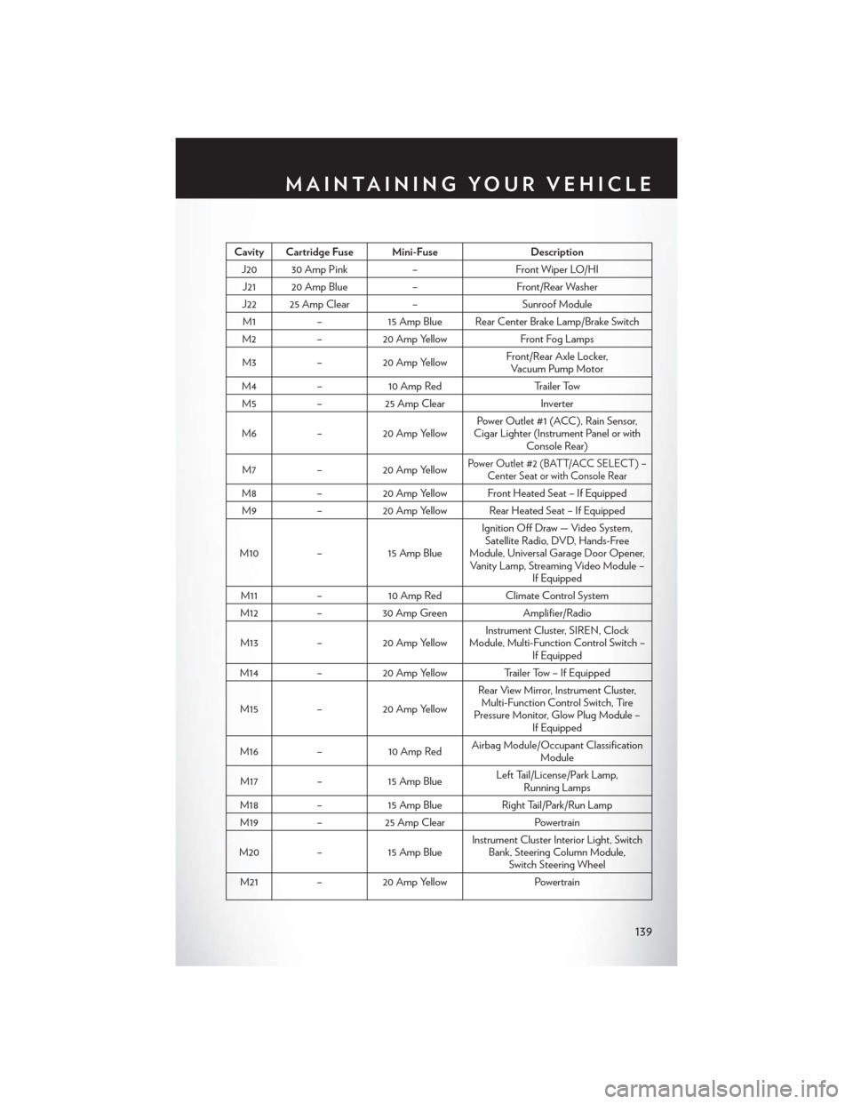
Cavity Cartridge Fuse Mini-FuseDescription
J20 30 Amp Pink–Front Wiper LO/HI
J21 20 Amp Blue–Front/Rear Washer
J22 25 Amp Clear–Sunroof Module
M1–15 Amp Blue Rear Center Brake Lamp/Brake Switch
M2–20 Amp YellowFront Fog Lamps
M3–20 Amp YellowFront/Rear Axle Locker,Vacuum Pump Motor
M4–10 Amp RedTr a i l e r To w
M5–25 Amp ClearInverter
M6–20 Amp YellowPower Outlet #1 (ACC ), Rain Sensor,Cigar Lighter (Instrument Panel or withConsole Rear)
M7–20 Amp YellowPower Outlet #2 (BATT/ACC SELECT ) –Center Seat or with Console Rear
M8–20 Amp Yellow Front Heated Seat – If Equipped
M9–20 Amp Yellow Rear Heated Seat – If Equipped
M10–15 Amp Blue
Ignition Off Draw — Video System,Satellite Radio, DVD, Hands-FreeModule, Universal Garage Door Opener,Vanity Lamp, Streaming Video Module –If Equipped
M11–10 Amp RedClimate Control System
M12–30 Amp GreenAmplifier/Radio
M13–20 Amp YellowInstrument Cluster, SIREN, ClockModule, Multi-Function Control Switch –If Equipped
M14–20 Amp YellowTrailer Tow – If Equipped
M15–20 Amp Yellow
Rear View Mirror, Instrument Cluster,Multi-Function Control Switch, TirePressure Monitor, Glow Plug Module –If Equipped
M16–10 Amp RedAirbag Module/Occupant ClassificationModule
M17–15 Amp BlueLeft Tail/License/Park Lamp,Running Lamps
M18–15 Amp BlueRight Tail/Park/Run Lamp
M19–25 Amp ClearPowertrain
M20–15 Amp BlueInstrument Cluster Interior Light, SwitchBank, Steering Column Module,Switch Steering Wheel
M21–20 Amp YellowPowertrain
MAINTAINING YOUR VEHICLE
139