wiring diagram CHRYSLER VOYAGER 1996 Owner's Manual
[x] Cancel search | Manufacturer: CHRYSLER, Model Year: 1996, Model line: VOYAGER, Model: CHRYSLER VOYAGER 1996Pages: 1938, PDF Size: 55.84 MB
Page 453 of 1938

LAMPS
CONTENTS
page page
BULB APPLICATION...................... 25
EXTERIOR LAMP BULB SERVICE............ 9
EXTERIOR LAMP SERVICE................. 14HEADLAMP ALIGNMENT................... 5
INTERIOR LAMPS........................ 18
LAMP DIAGNOSIS........................ 1
LAMP DIAGNOSIS
INDEX
page page
GENERAL INFORMATION
ELECTRONIC DAYTIME RUNNING LIGHT (DRL).1
GENERAL INFORMATION.................. 1SAFETY PRECAUTIONS................... 1
DIAGNOSIS AND TESTING
DIAGNOSTIC PROCEDURES................ 2
GENERAL INFORMATION
GENERAL INFORMATION
NS vehicles use lighting on the interior and exte-
rior of the vehicle for illuminating and indicating
purposes. Lighting circuits are protected by fuses.
Lighting circuits require an overload protected power
source, on/off device, lamps and body ground to oper-
ate properly. Plastic lamps require a wire in the har-
ness to supply body ground to the lamp socket.
Replace sockets and bulbs that are corroded.
Some of the interior and exterior lighting functions
are governed by the body controller. The headlamp,
dome, and the door ajar switches provide signals to
the body controller. The body controller in turn acti-
vates relay(s) in order to provide either a ground or
feed line to the appropriate lamp(s).
Wire connectors can make intermittent contact or
become corroded. Before coupling wire connectors,
inspect the terminals inside the connector. Male ter-
minals should not be bent or disengaged from the
insulator. Female terminals should not be sprung
open or disengaged from the insulator. Bent and
sprung terminals can be repaired using needle nose
pliers and pick tool. Corroded terminals appear
chalky or green. Corroded terminals should be
replaced to avoid recurrence of the problem symp-
toms.
Begin electrical system failure diagnosis by testing
related fuses in the fuse block and power distribution
center. Verify that bulbs are in good condition andtest continuity of the circuit ground. Refer to Group
8W, Wiring Diagrams, for component location and cir-
cuit information.SAFETY PRECAUTIONS
WARNING: EYE PROTECTION SHOULD BE USED
WHEN SERVICING GLASS COMPONENTS. PER-
SONAL INJURY CAN RESULT.
CAUTION: Do not touch the glass of halogen bulbs
with fingers or other possibly oily surface, reduced
bulb life will result.
Do not use bulbs with higher candle power than
indicated in the Bulb Application table at the end of
this group. Damage to lamp and/or Daytime Run-
ning Lamp Module can result.
Do not use fuses, circuit breakers or relays hav-
ing greater amperage value than indicated on the
fuse panel or in the Owners Manual.
When it is necessary to remove components to ser-
vice another, it should not be necessary to apply
excessive force or bend a component to remove it.
Before damaging a trim component, verify hidden
fasteners or captured edges are not holding the com-
ponent in place.
ELECTRONIC DAYTIME RUNNING LIGHT (DRL)
The Combination Flasher/DRL is a module provid-
ing turn signal, hazard warning, and daytime run-
NSLAMPS 8L - 1
Page 466 of 1938
EXTERIOR LAMP SERVICE
INDEX
page page
GENERAL INFORMATION
HEADLAMP DIMMER SWITCH.............. 14
HEADLAMP MODULE.................... 14
HEADLAMP SWITCH..................... 14
REMOVAL AND INSTALLATION
CENTER HIGH MOUNTED STOP LAMP
(CHMSL)............................. 17
FOG LAMP ± TOWN and COUNTRY......... 15
FOG LAMP............................. 14FRONT PARKING AND TURN SIGNAL LAMP ±
TOWN and COUNTRY.................. 15
FRONT SIDE MARKER LAMP TOWN and
COUNTRY............................ 15
HEADLAMP MODULE.................... 14
LICENSE PLATE LAMP................... 16
TAIL, STOP, TURN SIGNAL AND BACK-UP
LAMP............................... 16
GENERAL INFORMATION
HEADLAMP MODULE
Minor amounts of fogging may occur around the
edges of the headlamp lens when exposed to humid
conditions. This is considered normal. The fogging
will dissipate with increased ambient temperature or
headlamp usage.
HEADLAMP SWITCH
Service procedures for the headlamp switch can be
found in Group 8E, Instrument Panel and Gauges.
More information can be found in Group 8W, Wiring
Diagrams.
HEADLAMP DIMMER SWITCH
The headlamp dimmer switch is incorporated into
the multi-function (turn signal) switch. Proper proce-
dures can be found in Group 8J, Turn Signal and
Flashers. More information can be found in Group
8W, Wiring Diagrams.
REMOVAL AND INSTALLATION
HEADLAMP MODULE
REMOVAL
(1) Release hood latch and open hood.
(2) From inside engine compartment, remove nuts
holding headlamp module to radiator closure panel.
(3) Remove screw holding top of module to closure
panel.
(4) Remove headlamp module from radiator clo-
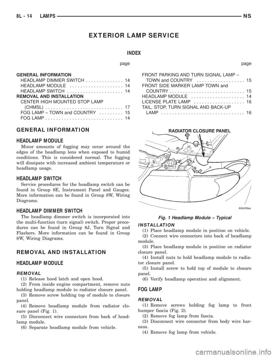
sure panel (Fig. 1).
(5) Disconnect wire connectors from back of head-
lamp module.
(6) Separate headlamp module from vehicle.
INSTALLATION
(1) Place headlamp module in position on vehicle.
(2) Connect wire connectors into back of headlamp
module.
(3) Place headlamp module in position on radiator
closure panel.
(4) Install nuts to hold headlamp module to radia-
tor closure panel.
(5) Install screw to hold top of module to closure
panel.
(6) Verify headlamp operation and alignment.
FOG LAMP
REMOVAL
(1) Remove screws holding fog lamp to front
bumper fascia (Fig. 2).
(2) Remove fog lamp from fascia.
(3) Disconnect wire connector from body wire har-
ness.
(4) Remove fog lamp from vehicle.
Fig. 1 Headlamp Module ± Typical
8L - 14 LAMPSNS
Page 479 of 1938
LAMPS
CONTENTS
page page
BULB APPLICATION..................... 17
HEADLAMP ALIGNMENT.................. 5
LAMP BULB SERVICE.................... 8LAMP DIAGNOSIS....................... 1
LAMP SERVICE........................ 13
LAMP DIAGNOSIS
INDEX
page page
GENERAL INFORMATION
HEADLAMP LEVELING MOTOR............. 2
INTRODUCTION........................ 1SAFETY PRECAUTIONS.................. 1
DIAGNOSIS AND TESTING
DIAGNOSTIC PROCEDURES.............. 2
GENERAL INFORMATION
INTRODUCTION
GS vehicles use lighting on the interior and exte-
rior of the vehicle for illuminating and indicating
purposes. Lighting circuits are protected by fuses.
Lighting circuits require an overload protected power
source, on/off device, lamps and body ground to oper-
ate properly. Plastic lamps require a wire in the har-
ness to supply body ground to the lamp socket.
Replace sockets and bulbs that are corroded.
Some of the interior and exterior lighting functions
are governed by the body controller. The headlamp,
dome, and the door ajar switches provide signals to
the body controller. The body controller in turn acti-
vates relay(s) in order to provide either a ground or
feed line to the appropriate lamp(s).
Wire connectors can make intermittent contact or
become corroded. Before coupling wire connectors,
inspect the terminals inside the connector. Male ter-
minals should not be bent or disengaged from the
insulator. Female terminals should not be sprung
open or disengaged from the insulator. Bent and
sprung terminals can be repaired using needle nose
pliers and pick tool. Corroded terminals appear
chalky or green. Corroded terminals should be
replaced to avoid recurrence of the problem symp-
toms.Begin electrical system failure diagnosis by testing
related fuses in the fuse block and power distribution
center. Verify that bulbs are in good condition and
test continuity of the circuit ground. Refer to Group
8W, Wiring Diagrams, for component location and cir-
cuit information.
SAFETY PRECAUTIONS
WARNING: EYE PROTECTION SHOULD BE USED
WHEN SERVICING GLASS COMPONENTS. PER-
SONAL INJURY CAN RESULT.
CAUTION: Do not touch the glass of halogen bulbs
with fingers or other possibly oily surface, reduced
bulb life will result.
Do not use bulbs with higher candle power than
indicated in the Bulb Application table at the end of
this group. Damage to lamp and/or Daytime Run-
ning Lamp Module can result.
Do not use fuses, circuit breakers or relays hav-
ing greater amperage value than indicated on the
fuse panel or in the Owners Manual.
When it is necessary to remove components to ser-
vice another, it should not be necessary to apply
excessive force or bend a component to remove it.
Before damaging a trim component, verify hidden
fasteners or captured edges are not holding the com-
ponent in place.
NS/GSLAMPS 8L - 1
Page 480 of 1938

HEADLAMP LEVELING MOTOR
This vehicle is equipped with a remote headlamp
leveling system. This system allows the driver to
adjust the vertical headlamp aim from the interior of
the vehicle to compensate for passenger or cargo
load. A headlamp leveling switch is located in the
instrument panel and controls the headlamp leveling
motor found on the back of the headlamp module.
DIAGNOSIS AND TESTING
DIAGNOSTIC PROCEDURES
When a vehicle experiences problems with the head-
lamp system, verify the condition of the battery connec-
tions, charging system, headlamp bulbs, wire
connectors, relay, high beam dimmer switch and head-
lamp switch. Refer to Group 8W, Wiring Diagrams, for
component locations and circuit information.
HEADLAMP DIAGNOSIS
CONDITION POSSIBLE CAUSES CORRECTION
HEADLAMPS ARE DIM
WITH ENGINE IDLING OR
IGNITION TURNED OFF1. Loose or corroded battery cables. 1. Clean and secure battery cable clamps
and posts.
2. Loose or worn alternator drive
belt.2. Adjust or replace alternator drive belt.
3. Charging system output too low. 3. Test and repair charging system. Refer
to Group 8A.
4. Battery has insufficient charge. 4. Test battery state-of -charge. Refer to
Group 8A.
5. Battery is sulfated or shorted. 5. Load test battery. Refer to Group 8A.
6. Poor lighting circuit Z1-ground. 6. Test for voltage drop across Z1-ground
locations. Refer to Group 8W.
HEADLAMP BULBS BURN
OUT FREQUENTLY1. Charging system output too high. 1. Test and repair charging system. Refer
to Group 8A.
2. Loose or corroded terminals or
splices in circuit.2. Inspect and repair all connectors and
splices. Refer to Group 8W.
HEADLAMPS ARE DIM
WITH ENGINE RUNNING
ABOVE IDLE1. Charging system output too low. 1. Test and repair charging system. Refer
to Group 8A.
2. Poor lighting circuit Z1-ground. 2. Test for voltage drop across Z1-ground
locations. Refer to Group 8W.
3. High resistance in headlamp
circuit.3. Test amperage draw of headlamp circuit.
HEADLAMPS FLASH
RANDOMLY1. Poor lighting circuit Z1-ground. 1. Test for voltage drop across Z1-ground
locations, refer to Group 8W.
2. High resistance in headlamp
circuit.2. Test amperage draw of headlamp circuit.
3. Loose or corroded terminals or
splices in circuit.3. Inspect and repair all connectors and
splices. Refer to Group 8W.
HEADLAMPS DO NOT
ILLUMINATE1. No voltage to headlamps. 1. Repair open headlamp circuit. Refer to
Group 8W.
2. No Z1-ground at headlamps. 2. Repair circuit ground. Refer to Group
8W.
3. Faulty headlamp switch. 3. Replace headlamp switch.
4. Faulty headlamp dimmer
(multi-function) switch.4. Replace multi-function switch.
5. Broken connector terminal or wire
splice in headlamp circuit.5. Repair connector terminal or wire splice.
6. Defective or burned out bulb. 6. Replace bulb.
7. Body controller malfunction. 7. Refer to appropriate body controller
diagnostics.
8L - 2 LAMPSNS/GS
GENERAL INFORMATION (Continued)
Page 491 of 1938
LAMP SERVICE
INDEX
page page
GENERAL INFORMATION
HEADLAMP DIMMER SWITCH............. 13
HEADLAMP SWITCH.................... 13
REMOVAL AND INSTALLATION
CENTER HIGH MOUNTED STOP LAMP
(CHMSL)............................ 16FOG LAMP............................ 14
HEADLAMP LEVELING MOTOR............ 14
HEADLAMP MODULE................... 13
LICENSE PLATE LAMP.................. 15
SIDE REPEATER LAMP.................. 14
TAIL LAMP............................ 15
GENERAL INFORMATION
HEADLAMP SWITCH
Service procedures for the headlamp switch can be
found in Group 8E, Instrument Panel and Gauges.
More information can be found in Group 8W, Wiring
Diagrams.
HEADLAMP DIMMER SWITCH
The headlamp dimmer switch is incorporated into
the multi-function (turn signal) switch. Proper proce-
dures can be found in Group 8J, Turn Signal and
Flashers. More information can be found in Group
8W, Wiring Diagrams.
REMOVAL AND INSTALLATION
HEADLAMP MODULE
REMOVAL
(1) Release hood latch and open hood.
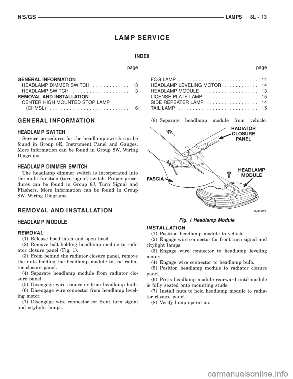
(2) Remove bolt holding headlamp module to radi-
ator closure panel (Fig. 1).
(3) From behind the radiator closure panel, remove
the nuts holding the headlamp module to the radia-
tor closure panel.
(4) Separate headlamp module from radiator clo-
sure panel.
(5) Disengage wire connector from headlamp bulb.
(6) Disengage wire connector from headlamp level-
ing motor.
(7) Disengage wire connector for front turn signal
and citylight lamps.(8) Separate headlamp module from vehicle.
INSTALLATION
(1) Position headlamp module to vehicle.
(2) Engage wire connector for front turn signal and
citylight lamps.
(3) Engage wire connector to headlamp leveling
motor.
(4) Engage wire connector to headlamp bulb.
(5) Position headlamp module to radiator closure
panel.
(6) Press headlamp module rearward until module
is fully seated onto mounting studs.
(7) Install nuts to hold headlamp module to radia-
tor closure panel.
(8) Verify lamp operation.
Fig. 1 Headlamp Module
NS/GSLAMPS 8L - 13
Page 505 of 1938
ELECTRICALLY HEATED SYSTEMS
CONTENTS
page page
DESCRIPTION AND OPERATION
HVAC MOUNTED SWITCH................. 1
INTRODUCTION......................... 1
DIAGNOSIS AND TESTING
GRID LINE TEST......................... 2SYSTEM TEST.......................... 2
SERVICE PROCEDURES
GRID LINE AND TERMINAL REPAIR......... 3
DESCRIPTION AND OPERATION
INTRODUCTION
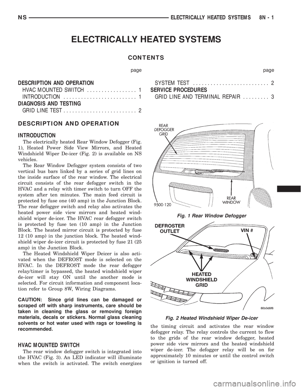
The electrically heated Rear Window Defogger (Fig.
1), Heated Power Side View Mirrors, and Heated
Windshield Wiper De-icer (Fig. 2) is available on NS
vehicles.
The Rear Window Defogger system consists of two
vertical bus bars linked by a series of grid lines on
the inside surface of the rear window. The electrical
circuit consists of the rear defogger switch in the
HVAC and a relay with timer switch to turn OFF the
system after ten minutes. The main feed circuit is
protected by fuse one (40 amp) in the Junction Block.
The rear defogger switch and relay also activates the
heated power side view mirrors and heated wind-
shield wiper de-icer. The HVAC rear defogger switch
is protected by fuse ten (10 amp) in the Junction
Block. The heated mirror circuit is protected by fuse
12 (10 amp) in the junction block. The heated wind-
shield wiper de-icer circuit is protected by fuse 21 (25
amp) in the Junction Block.
The Heated Windshield Wiper Deicer is also acti-
vated when the DEFROST mode is selected on the
HVAC. In the DEFROST mode the rear defogger
relay/timer is bypassed, the heated windshield wiper
de-icer will stay ON until the another mode is
selected. For circuit information and component loca-
tion refer to Group 8W, Wiring Diagrams.
CAUTION: Since grid lines can be damaged or
scraped off with sharp instruments, care should be
taken in cleaning the glass or removing foreign
materials, decals or stickers. Normal glass cleaning
solvents or hot water used with rags or toweling is
recommended.
HVAC MOUNTED SWITCH
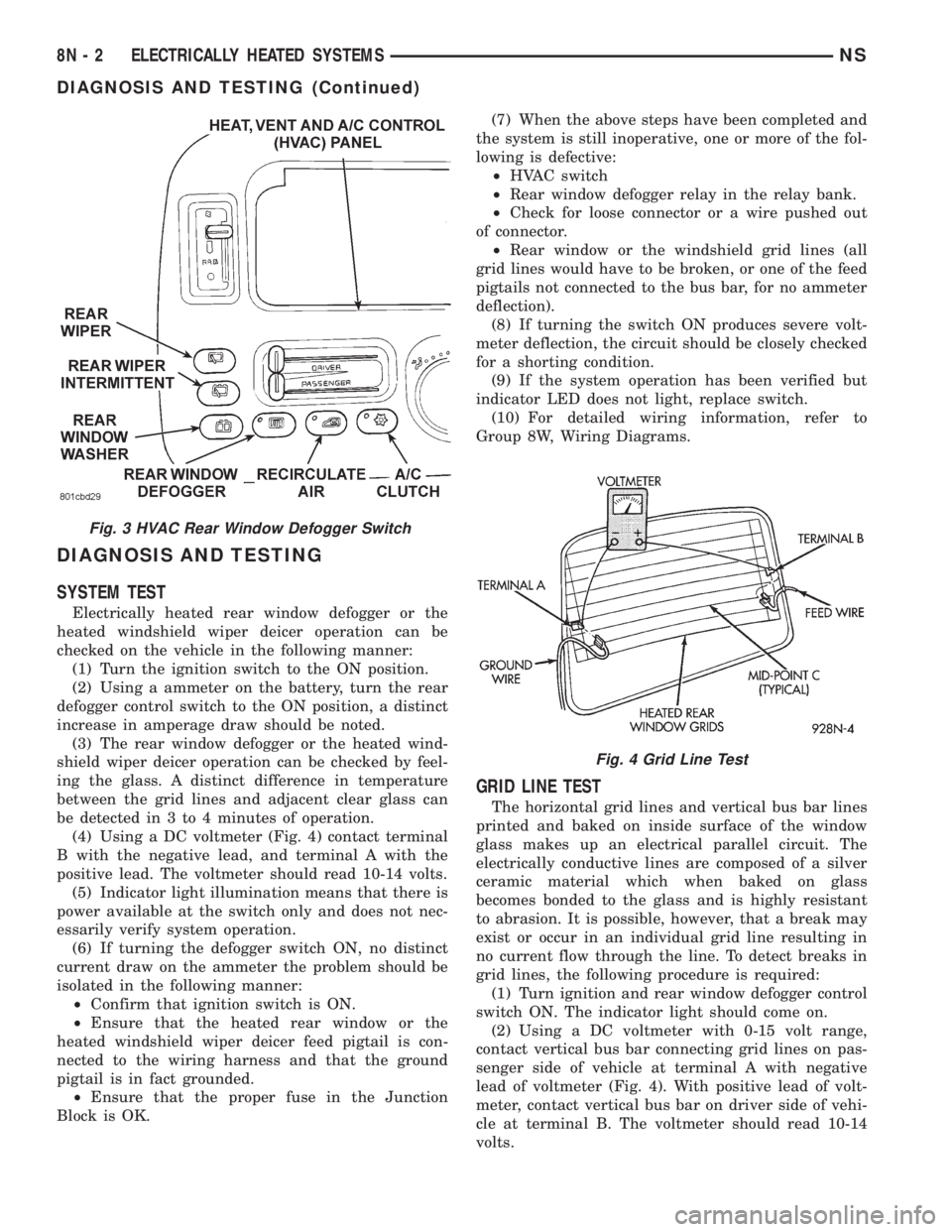
The rear window defogger switch is integrated into
the HVAC (Fig. 3). An LED indicator will illuminate
when the switch is activated. The switch energizesthe timing circuit and activates the rear window
defogger relay. The relay controls the current to flow
to the grids of the rear window defogger, heated
power side view mirrors and the heated windshield
wiper de-icer. The defogger relay will be on for
approximately 10 minutes or until the control switch
or ignition is turned off.
Fig. 1 Rear Window Defogger
Fig. 2 Heated Windshield Wiper De-icer
NSELECTRICALLY HEATED SYSTEMS 8N - 1
Page 506 of 1938
DIAGNOSIS AND TESTING
SYSTEM TEST
Electrically heated rear window defogger or the
heated windshield wiper deicer operation can be
checked on the vehicle in the following manner:
(1) Turn the ignition switch to the ON position.
(2) Using a ammeter on the battery, turn the rear
defogger control switch to the ON position, a distinct
increase in amperage draw should be noted.
(3) The rear window defogger or the heated wind-
shield wiper deicer operation can be checked by feel-
ing the glass. A distinct difference in temperature
between the grid lines and adjacent clear glass can
be detected in 3 to 4 minutes of operation.
(4) Using a DC voltmeter (Fig. 4) contact terminal
B with the negative lead, and terminal A with the
positive lead. The voltmeter should read 10-14 volts.
(5) Indicator light illumination means that there is
power available at the switch only and does not nec-
essarily verify system operation.
(6) If turning the defogger switch ON, no distinct
current draw on the ammeter the problem should be
isolated in the following manner:
²Confirm that ignition switch is ON.
²Ensure that the heated rear window or the
heated windshield wiper deicer feed pigtail is con-
nected to the wiring harness and that the ground
pigtail is in fact grounded.
²Ensure that the proper fuse in the Junction
Block is OK.(7) When the above steps have been completed and
the system is still inoperative, one or more of the fol-
lowing is defective:
²HVAC switch
²Rear window defogger relay in the relay bank.
²Check for loose connector or a wire pushed out
of connector.
²Rear window or the windshield grid lines (all
grid lines would have to be broken, or one of the feed
pigtails not connected to the bus bar, for no ammeter
deflection).
(8) If turning the switch ON produces severe volt-
meter deflection, the circuit should be closely checked
for a shorting condition.
(9) If the system operation has been verified but
indicator LED does not light, replace switch.
(10) For detailed wiring information, refer to
Group 8W, Wiring Diagrams.
GRID LINE TEST
The horizontal grid lines and vertical bus bar lines
printed and baked on inside surface of the window
glass makes up an electrical parallel circuit. The
electrically conductive lines are composed of a silver
ceramic material which when baked on glass
becomes bonded to the glass and is highly resistant
to abrasion. It is possible, however, that a break may
exist or occur in an individual grid line resulting in
no current flow through the line. To detect breaks in
grid lines, the following procedure is required:
(1) Turn ignition and rear window defogger control
switch ON. The indicator light should come on.
(2) Using a DC voltmeter with 0-15 volt range,
contact vertical bus bar connecting grid lines on pas-
senger side of vehicle at terminal A with negative
lead of voltmeter (Fig. 4). With positive lead of volt-
meter, contact vertical bus bar on driver side of vehi-
cle at terminal B. The voltmeter should read 10-14
volts.
Fig. 3 HVAC Rear Window Defogger Switch
Fig. 4 Grid Line Test
8N - 2 ELECTRICALLY HEATED SYSTEMSNS
DIAGNOSIS AND TESTING (Continued)
Page 510 of 1938

DOOR LOCK INHIBIT FEATURE
The BCM cancels out the door lock switch actua-
tion, when the key is in the Ignition Switch and a
door is open. After the key is removed from the Igni-
tion Switch, or the doors are closed, the power door
locks will operate normally.
SLIDING DOOR LOCK MEMORY FEATURE
The door locks on the sliding door(s) can be actu-
ated when the door(s) are closed. If the sliding
door(s) are open when the door locks are actuated,
the BCM will hold the lock command in memory
until the door(s) is closed. When the door is closed
and the door jamb terminals make contact, signaling
the BCM to lock the sliding door(s) automatically.
Actuating the door lock switch to the unlock position
before the sliding door(s) are closed will cancel the
lock request.
DIAGNOSIS AND TESTING
AUTOMATIC DOOR LOCK SYSTEM TEST
When using a scan tool (DRB) for testing the auto-
matic door lock system, refer to the Body Diagnostic
Procedures Manual. Refer to Group 8W, Wiring Dia-
grams for circuit information and component loca-
tions.
DOOR LOCK MOTOR
Verify battery condition before testing door lock
motor(s), refer to Group 8A, Battery for proper diag-
nosis procedures.
To determine which motor is faulty, check each
individual door for electrical lock and unlock or dis-
connect the motor connectors one at a time, while
operating the door lock switch. In the event that
none of the motors work, the problem may be caused
by a shorted motor, a relay or a bad switch. Discon-
necting the defective motor will allow the others to
work.
To test an individual door lock motor, disconnect
the electrical connector from the motor. To lock the
door, connect a 12 volt power source to the positive
pin of the lock motor and a ground wire to the other
pin (Fig. 1), (Fig. 2), (Fig. 3) and refer to Group 8W,
Wiring Diagrams for pin locations. To unlock the door
reverse the wire connections at the motor pin termi-
nals. If these results are NOT obtained, replace the
motor.
DOOR LOCK SWITCH TEST
(1) Remove door lock switch bezel assembly from
door. Refer to Group 23, Body for removal proce-
dures.
(2) Disconnect wire connector from back of door
lock switch.(3) Depress switch to LOCK position.
(4) Using an ohmmeter, test switch resistance
between Pins 2 and 3. Refer to Door Lock Switch
Test and (Fig. 4).
(5) Depress switch to UNLOCK position.
(6) Test resistance between Pins 2 and 3.
(7) If resistance values are not within the param-
eters shown replace the door lock switch.
Fig. 1 Sliding Door Lock Motor±Typical
Fig. 2 Front Door Lock Motor
8P - 2 POWER DOOR LOCKSNS
DESCRIPTION AND OPERATION (Continued)
Page 513 of 1938
REMOTE KEYLESS ENTRY
INDEX
page page
DESCRIPTION AND OPERATION
INTRODUCTION......................... 5
VEHICLE ACCESS CODE (VAC)
PROGRAMMING........................ 5
DIAGNOSIS AND TESTING
RKE DIAGNOSTICS....................... 5
SERVICE PROCEDURES
HORN CHIRP DISABLE OR ENABLE.......... 6REMOVAL AND INSTALLATION
RKE MODULE........................... 6
ADJUSTMENTS
PROGRAMMING RKE MODULE.............. 6
SPECIFICATIONS
RKE TRANSMITTER BATTERY.............. 6
RKE TRANSMITTER RANGE................ 6
DESCRIPTION AND OPERATION
INTRODUCTION
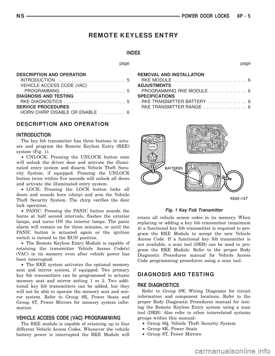
The key fob transmitter has three buttons to actu-
ate and program the Remote Keyless Entry (RKE)
system (Fig. 1).
²UNLOCK: Pressing the UNLOCK button once
will unlock the driver door and activate the illumi-
nated entry system and disarm Vehicle Theft Secu-
rity System, if equipped. Pressing the UNLOCK
button twice within five seconds will unlock all doors
and activate the illuminated entry system.
²LOCK: Pressing the LOCK button locks all
doors and sounds horn (chirp) and arm the Vehicle
Theft Security System. The chirp verifies the door
lock operation.
²PANIC: Pressing the PANIC button sounds the
horns at half second intervals, flashes the exterior
lamps, and turns ON the interior lamps. The panic
alarm will remain on for three minutes, or until the
PANIC button is actuated again or the ignition
switch is turned to the RUN position.
²The Remote Keyless Entry Module is capable of
retaining the transmitter Vehicle Access Code(s)
(VAC) in its memory even after vehicle power has
been interrupted.
²The RKE system activates the optional memory
seat and mirror system, if equipped. Two primary
key fob transmitters can be programmed to actuate
memory seat and mirror setting 1 or 2. Two addi-
tional key fob transmitters can be added, but they
will not be able to operate the memory seat and mir-
ror system. Refer to Group 8R, Power Seats and
Group 8T, Power Mirrors for memory system infor-
mation.
VEHICLE ACCESS CODE (VAC) PROGRAMMING
The RKE module is capable of retaining up to four
different Vehicle Access Codes. Whenever the vehicle
battery power is interrupted the RKE Module willretain all vehicle access codes in its memory. When
replacing or adding a key fob transmitter (maximum
4) a functional key fob transmitter is required to pro-
gram the RKE Module to accept the new Vehicle
Access Code. If a functional key fob transmitter is
not available, a scan tool (DRB) can be used to pro-
gram the RKE Module. Refer to the proper Body
Diagnostic Procedures manual for Vehicle Access
Code programming procedures using a scan tool.
DIAGNOSIS AND TESTING
RKE DIAGNOSTICS
Refer to Group 8W, Wiring Diagrams for circuit
information and component locations. Refer to the
proper Body Diagnostic Procedures manual for test-
ing the Remote Keyless Entry system using a scan
tool (DRB). Also refer to other interrelated systems
groups within this manual:
²Group 8Q, Vehicle Theft Security System
²Group 8R, Power Seats
²Group 8T, Power Mirrors
Fig. 1 Key Fob Transmitter
NSPOWER DOOR LOCKS 8P - 5
Page 516 of 1938
TIME-OUT PERIOD
The VTSS requires 16 consecutive seconds to time-
out and arm the alarm. If a door is key unlocked, key
fob unlocked. or the ignition is switched ON, the
VTSS will cancel out. To reset the VTSS, perform
methods A or B.
TRIGGERING THE VTSS
After the VTSS is armed, following actions will
trigger the alarm:
²Opening any door.
²Opening the hood
²Turning the ignition to the ON or unlock posi-
tion.
²The ignition switch can be turned to the acces-
sory position without triggering alarm system.
DIAGNOSIS AND TESTING
DIAGNOSTIC PROCEDURES
Refer to Group 8W, Wiring Diagrams for circuit
information and component locations. Using a scan
tool (DRB). Refer to the proper Body Diagnostic Pro-
cedures manual for test procedures.
REMOVAL AND INSTALLATION
BODY CONTROL MODULE
REMOVAL
(1) Disconnect the battery negative cable.
(2) Remove the lower steering column cover and
the knee blocker reinforcement.
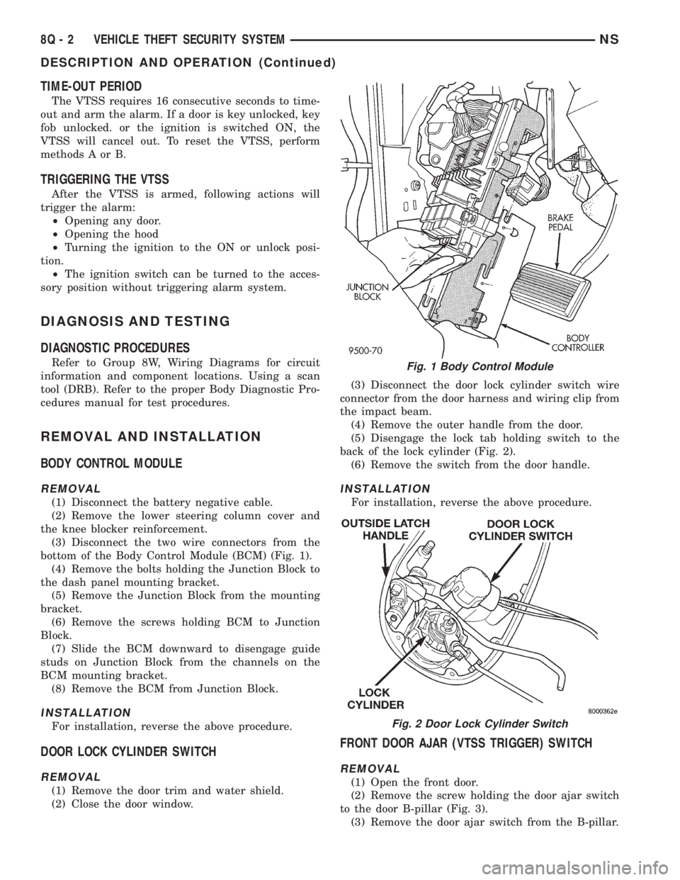
(3) Disconnect the two wire connectors from the
bottom of the Body Control Module (BCM) (Fig. 1).
(4) Remove the bolts holding the Junction Block to
the dash panel mounting bracket.
(5) Remove the Junction Block from the mounting
bracket.
(6) Remove the screws holding BCM to Junction
Block.
(7) Slide the BCM downward to disengage guide
studs on Junction Block from the channels on the
BCM mounting bracket.
(8) Remove the BCM from Junction Block.
INSTALLATION
For installation, reverse the above procedure.
DOOR LOCK CYLINDER SWITCH
REMOVAL
(1) Remove the door trim and water shield.
(2) Close the door window.(3) Disconnect the door lock cylinder switch wire
connector from the door harness and wiring clip from
the impact beam.
(4) Remove the outer handle from the door.
(5) Disengage the lock tab holding switch to the
back of the lock cylinder (Fig. 2).
(6) Remove the switch from the door handle.
INSTALLATION
For installation, reverse the above procedure.
FRONT DOOR AJAR (VTSS TRIGGER) SWITCH
REMOVAL
(1) Open the front door.
(2) Remove the screw holding the door ajar switch
to the door B-pillar (Fig. 3).
(3) Remove the door ajar switch from the B-pillar.
Fig. 1 Body Control Module
Fig. 2 Door Lock Cylinder Switch
8Q - 2 VEHICLE THEFT SECURITY SYSTEMNS
DESCRIPTION AND OPERATION (Continued)