torque CHRYSLER VOYAGER 1996 Service Manual
[x] Cancel search | Manufacturer: CHRYSLER, Model Year: 1996, Model line: VOYAGER, Model: CHRYSLER VOYAGER 1996Pages: 1938, PDF Size: 55.84 MB
Page 1775 of 1938
(18) Pass front seat belt and turning loop through
slot in quarter trim panel on three door vehicle.
(19) Pass first rear seat belt through slot in quar-
ter trim panel.
(20) Pass second rear seat belt, if equipped,
through slot in quarter trim panel on long wheel
base vehicle.
(21) Remove quarter trim panel from vehicle.
INSTALLATION
(1) Position quarter trim panel on vehicle.
(2) Pass second rear seat belt, if equipped, through
slot in quarter trim panel on long wheel base vehicle.
(3) Pass first rear seat belt through slot in quarter
trim panel.
(4) Pass front seat belt through slot in quarter
trim panel on three door vehicle.
(5) Connect wire connector into accessory power
outlet, if equipped.
(6) Align locating pins on backside of trim panel to
mating holes in inner panels.
(7) Position quarter trim panel on inner quarter
panel.
(8) Install screws to hold top of trim panel to inner
sheet metal between B-pillar and C-pillar on three
door vehicle.(9) Install screws to hold rear edge of quarter trim
to attaching bracket or inner quarter panel.
(10) Install screws to hold quarter trim to inner
quarter panel in bolster area.
(11) Install screws to hold quarter trim to inner
quarter panel in B-pillar area on three door vehicle.
(12) Install left front seat belt opening bezel into
quarter trim on three door vehicle.
(13) Install second rear seat belts anchor on long
wheel base vehicle. Tighten all seat belt bolts to 39
N´m (28 in. lbs.) torque.
(14) Install first rear seat belt anchor.
(15) Install left D-pillar trim panel.
(16) Install C-pillar trim panel.
(17) Install upper left B-pillar trim on three door
vehicle.
(18) Install left quarter trim bolster.
(19) Install front door sill plate on three door vehi-
cle.
(20) Install sliding door sill plate on four door
vehicle.
(21) Install second rear seat, if equipped.
(22) Install first rear seat.
(23) Connect the battery negative cable.
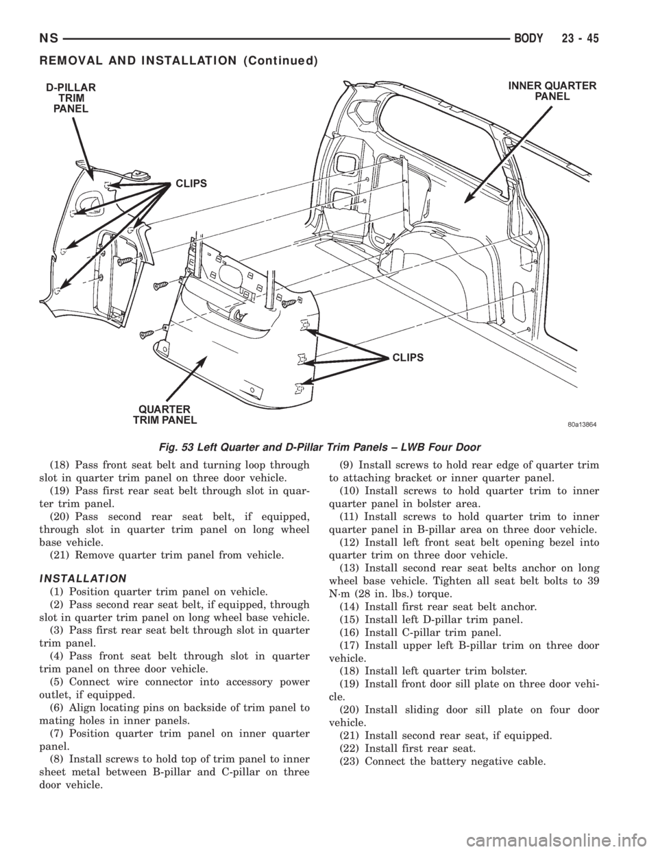
Fig. 53 Left Quarter and D-Pillar Trim Panels ± LWB Four Door
NSBODY 23 - 45
REMOVAL AND INSTALLATION (Continued)
Page 1781 of 1938
(2) Engage hidden clips to hold molding to liftgate
upper frame (Fig. 66).
LIFTGATE UPPER FRAME SIDE MOLDINGS
REMOVAL
(1) Remove liftgate upper frame molding.
(2) Disengage hidden clips holding side moldings
to liftgate upper frame (Fig. 66).
(3) Remove liftgate upper frame side molding from
vehicle.
INSTALLATION
(1) Place liftgate upper frame side moldings in
position on vehicle.
(2) Engage hidden clips to hold side moldings to
liftgate upper frame (Fig. 66).
(3) Install liftgate upper frame molding.
LOWER B-PILLAR TRIM COVER
REMOVAL
(1) Slide lower seat belt cover rearward to expose
anchor bolt.
(2) Remove bolt holding lower seat belt anchor to
floor.
(3) Remove upper B-pillar trim cover.
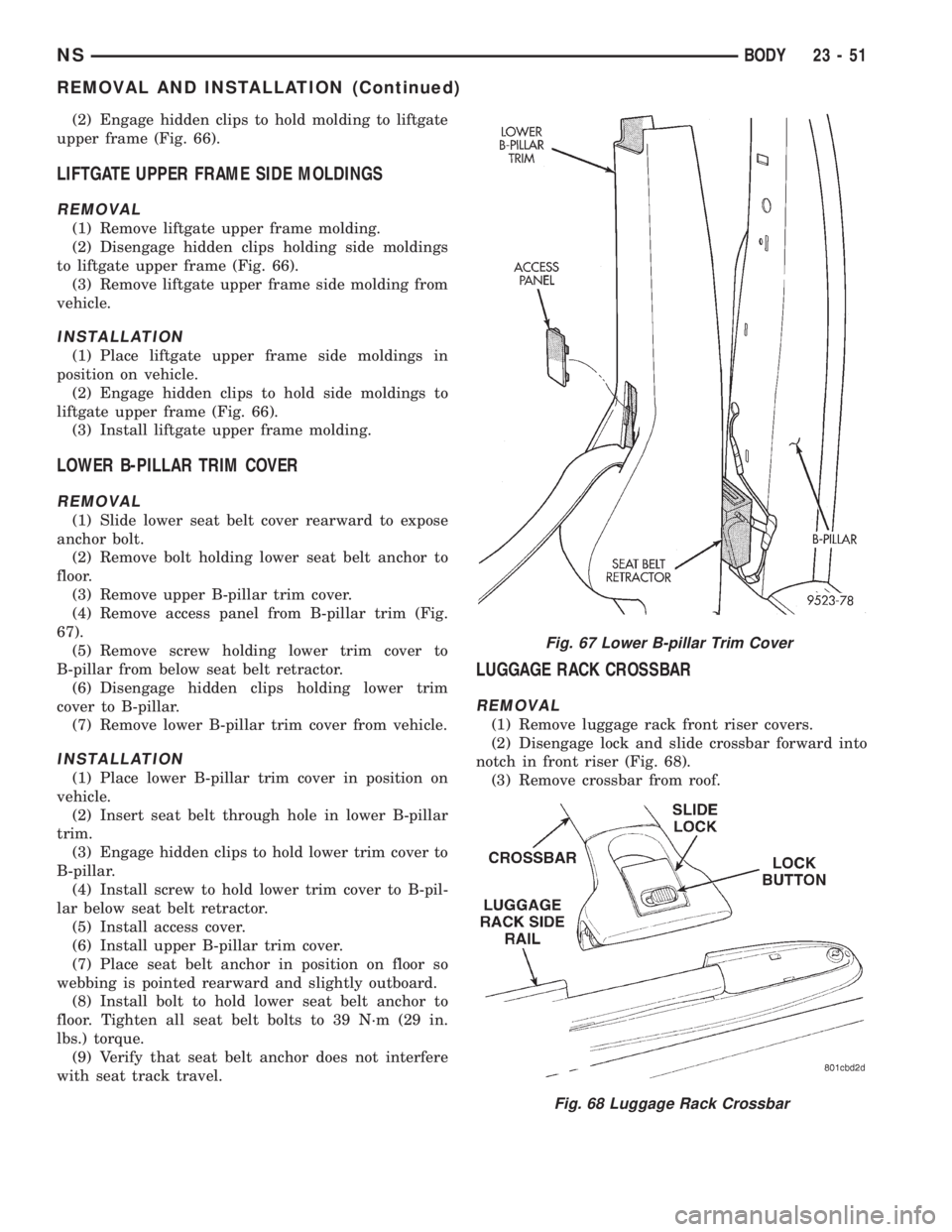
(4) Remove access panel from B-pillar trim (Fig.
67).
(5) Remove screw holding lower trim cover to
B-pillar from below seat belt retractor.
(6) Disengage hidden clips holding lower trim
cover to B-pillar.
(7) Remove lower B-pillar trim cover from vehicle.
INSTALLATION
(1) Place lower B-pillar trim cover in position on
vehicle.
(2) Insert seat belt through hole in lower B-pillar
trim.
(3) Engage hidden clips to hold lower trim cover to
B-pillar.
(4) Install screw to hold lower trim cover to B-pil-
lar below seat belt retractor.
(5) Install access cover.
(6) Install upper B-pillar trim cover.
(7) Place seat belt anchor in position on floor so
webbing is pointed rearward and slightly outboard.
(8) Install bolt to hold lower seat belt anchor to
floor. Tighten all seat belt bolts to 39 N´m (29 in.
lbs.) torque.
(9) Verify that seat belt anchor does not interfere
with seat track travel.
LUGGAGE RACK CROSSBAR
REMOVAL
(1) Remove luggage rack front riser covers.
(2) Disengage lock and slide crossbar forward into
notch in front riser (Fig. 68).
(3) Remove crossbar from roof.
Fig. 67 Lower B-pillar Trim Cover
Fig. 68 Luggage Rack Crossbar
NSBODY 23 - 51
REMOVAL AND INSTALLATION (Continued)
Page 1785 of 1938
REAR HVAC LOUVER AND BEZEL
REMOVAL
(1) Using a trim stick (C-4755), pry edge of louver
from bezel.
(2) Remove HVAC louver from bezel.
(3) Using a trim stick, pry lower edge of HVAC
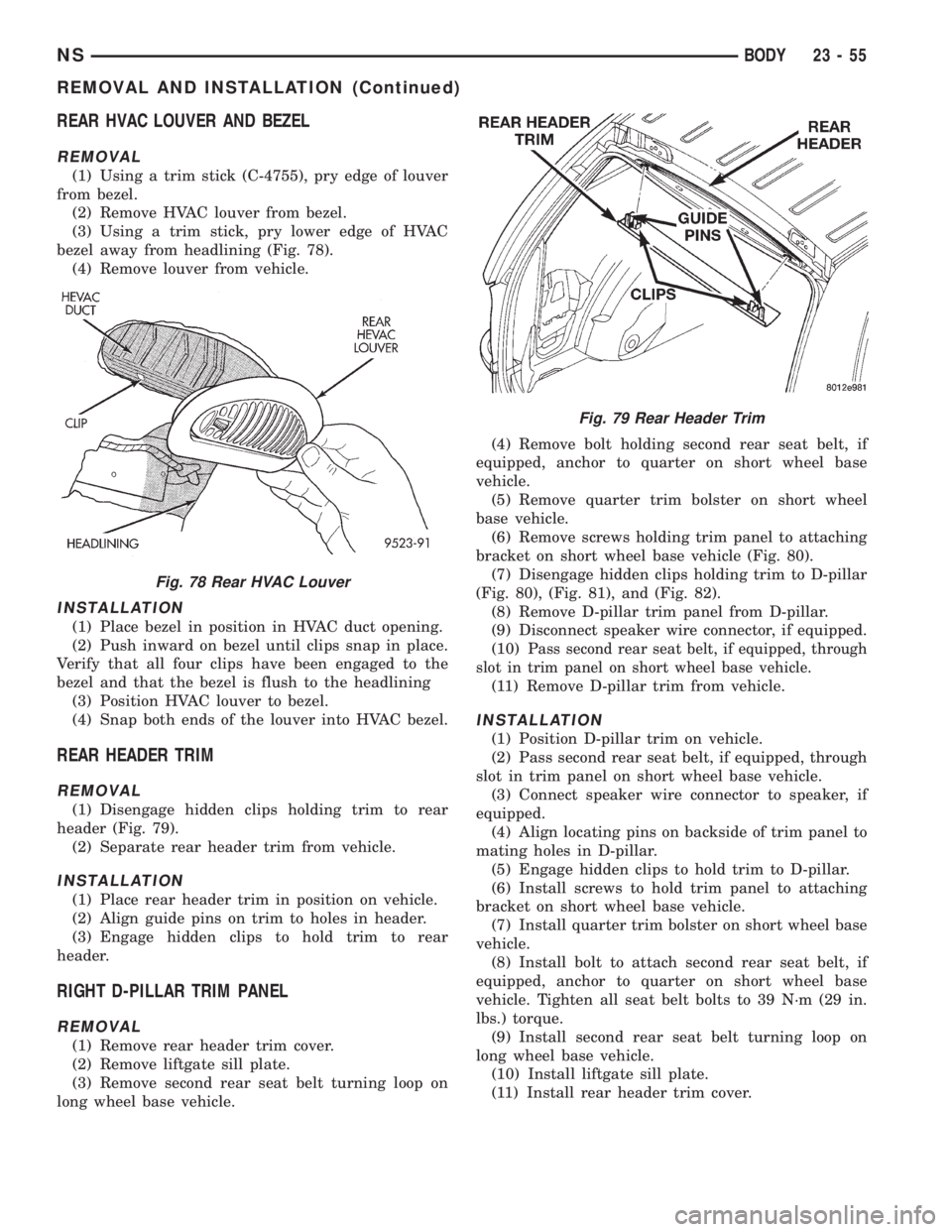
bezel away from headlining (Fig. 78).
(4) Remove louver from vehicle.
INSTALLATION
(1) Place bezel in position in HVAC duct opening.
(2) Push inward on bezel until clips snap in place.
Verify that all four clips have been engaged to the
bezel and that the bezel is flush to the headlining
(3) Position HVAC louver to bezel.
(4) Snap both ends of the louver into HVAC bezel.
REAR HEADER TRIM
REMOVAL
(1) Disengage hidden clips holding trim to rear
header (Fig. 79).
(2) Separate rear header trim from vehicle.
INSTALLATION
(1) Place rear header trim in position on vehicle.
(2) Align guide pins on trim to holes in header.
(3) Engage hidden clips to hold trim to rear
header.
RIGHT D-PILLAR TRIM PANEL
REMOVAL
(1) Remove rear header trim cover.
(2) Remove liftgate sill plate.
(3) Remove second rear seat belt turning loop on
long wheel base vehicle.(4) Remove bolt holding second rear seat belt, if
equipped, anchor to quarter on short wheel base
vehicle.
(5) Remove quarter trim bolster on short wheel
base vehicle.
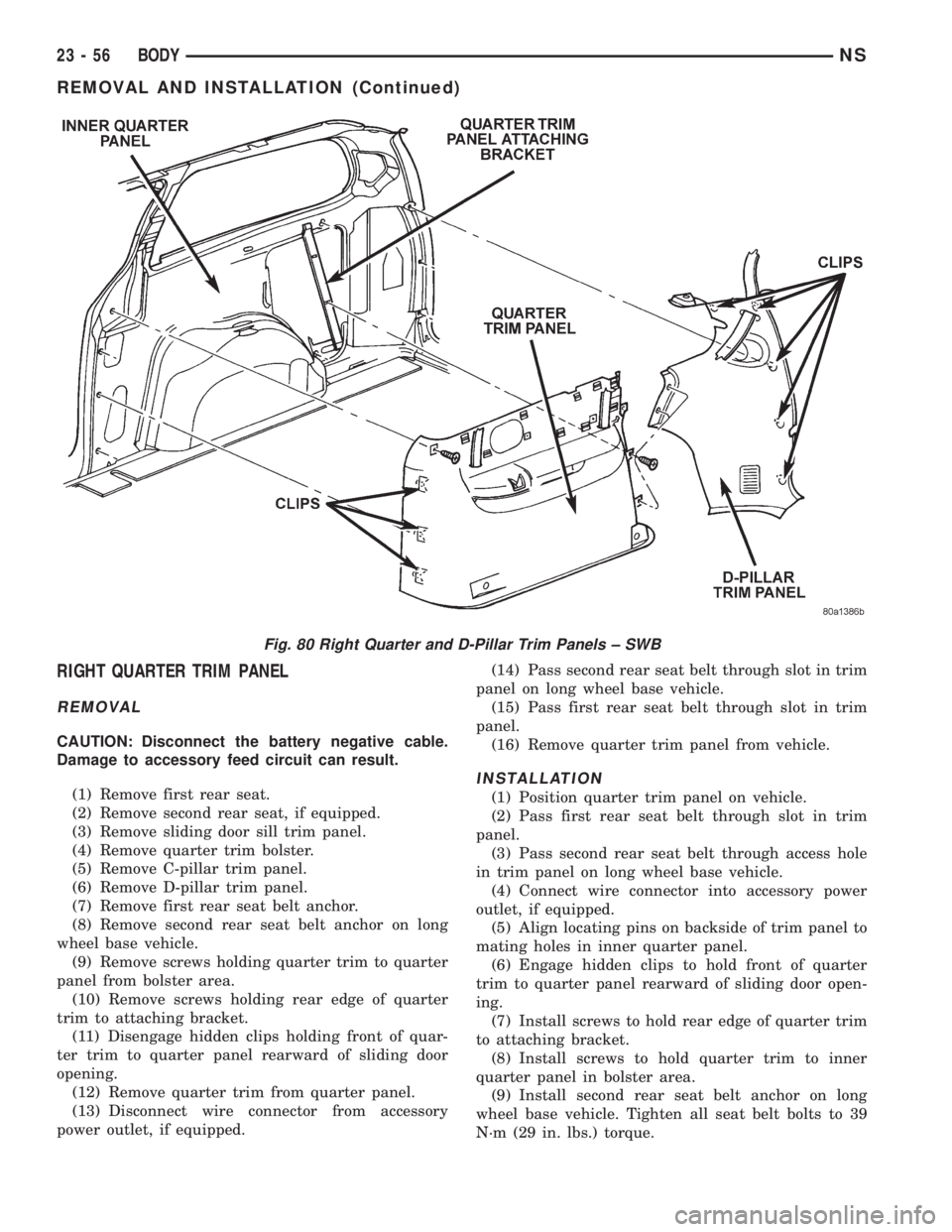
(6) Remove screws holding trim panel to attaching
bracket on short wheel base vehicle (Fig. 80).
(7) Disengage hidden clips holding trim to D-pillar
(Fig. 80), (Fig. 81), and (Fig. 82).
(8) Remove D-pillar trim panel from D-pillar.
(9) Disconnect speaker wire connector, if equipped.
(10) P
ass second rear seat belt, if equipped, through
slot in trim panel on short wheel base vehicle.
(11) Remove D-pillar trim from vehicle.
INSTALLATION
(1) Position D-pillar trim on vehicle.
(2) Pass second rear seat belt, if equipped, through
slot in trim panel on short wheel base vehicle.
(3) Connect speaker wire connector to speaker, if
equipped.
(4) Align locating pins on backside of trim panel to
mating holes in D-pillar.
(5) Engage hidden clips to hold trim to D-pillar.
(6) Install screws to hold trim panel to attaching
bracket on short wheel base vehicle.
(7) Install quarter trim bolster on short wheel base
vehicle.
(8) Install bolt to attach second rear seat belt, if
equipped, anchor to quarter on short wheel base
vehicle. Tighten all seat belt bolts to 39 N´m (29 in.
lbs.) torque.
(9) Install second rear seat belt turning loop on
long wheel base vehicle.
(10) Install liftgate sill plate.
(11) Install rear header trim cover.
Fig. 78 Rear HVAC Louver
Fig. 79 Rear Header Trim
NSBODY 23 - 55
REMOVAL AND INSTALLATION (Continued)
Page 1786 of 1938
RIGHT QUARTER TRIM PANEL
REMOVAL
CAUTION: Disconnect the battery negative cable.
Damage to accessory feed circuit can result.
(1) Remove first rear seat.
(2) Remove second rear seat, if equipped.
(3) Remove sliding door sill trim panel.
(4) Remove quarter trim bolster.
(5) Remove C-pillar trim panel.
(6) Remove D-pillar trim panel.
(7) Remove first rear seat belt anchor.
(8) Remove second rear seat belt anchor on long
wheel base vehicle.
(9) Remove screws holding quarter trim to quarter
panel from bolster area.
(10) Remove screws holding rear edge of quarter
trim to attaching bracket.
(11) Disengage hidden clips holding front of quar-
ter trim to quarter panel rearward of sliding door
opening.
(12) Remove quarter trim from quarter panel.
(13) Disconnect wire connector from accessory
power outlet, if equipped.(14) Pass second rear seat belt through slot in trim
panel on long wheel base vehicle.
(15) Pass first rear seat belt through slot in trim
panel.
(16) Remove quarter trim panel from vehicle.
INSTALLATION
(1) Position quarter trim panel on vehicle.
(2) Pass first rear seat belt through slot in trim
panel.
(3) Pass second rear seat belt through access hole
in trim panel on long wheel base vehicle.
(4) Connect wire connector into accessory power
outlet, if equipped.
(5) Align locating pins on backside of trim panel to
mating holes in inner quarter panel.
(6) Engage hidden clips to hold front of quarter
trim to quarter panel rearward of sliding door open-
ing.
(7) Install screws to hold rear edge of quarter trim
to attaching bracket.
(8) Install screws to hold quarter trim to inner
quarter panel in bolster area.
(9) Install second rear seat belt anchor on long
wheel base vehicle. Tighten all seat belt bolts to 39
N´m (29 in. lbs.) torque.
Fig. 80 Right Quarter and D-Pillar Trim Panels ± SWB
23 - 56 BODYNS
REMOVAL AND INSTALLATION (Continued)
Page 1788 of 1938
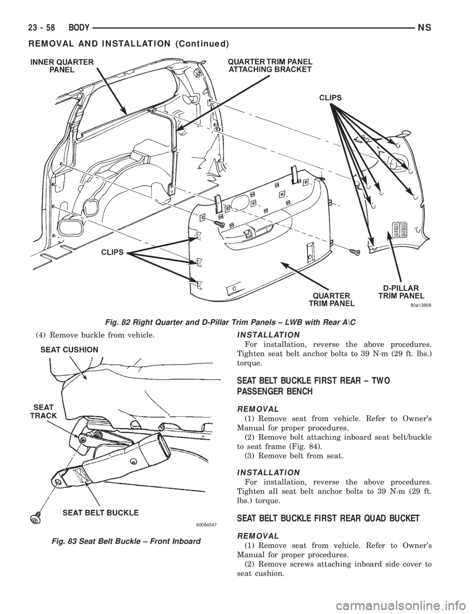
(4) Remove buckle from vehicle.INSTALLATION
For installation, reverse the above procedures.
Tighten seat belt anchor bolts to 39 N´m (29 ft. lbs.)
torque.
SEAT BELT BUCKLE FIRST REAR ± TWO
PASSENGER BENCH
REMOVAL
(1) Remove seat from vehicle. Refer to Owner's
Manual for proper procedures.
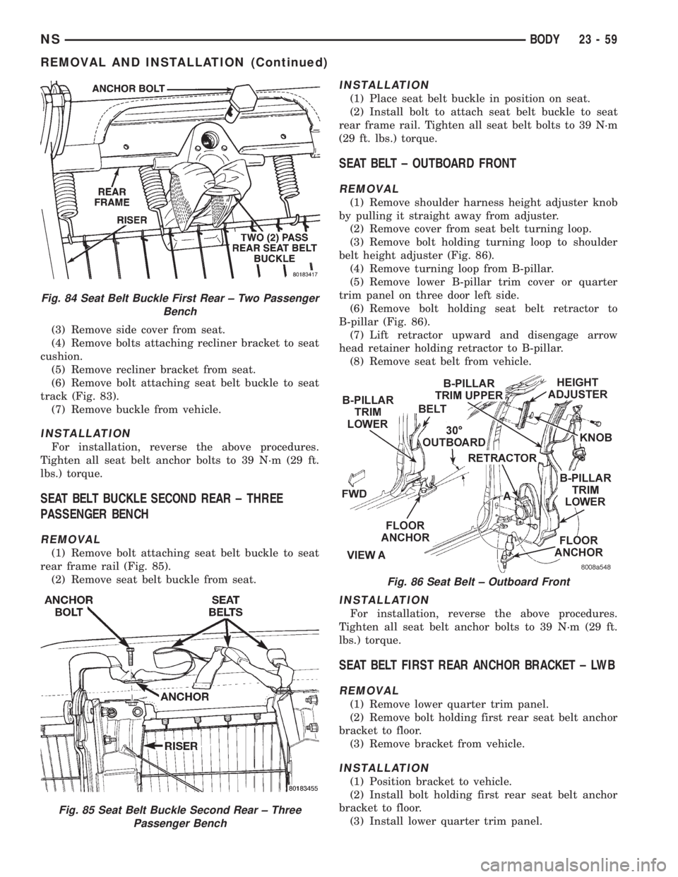
(2) Remove bolt attaching inboard seat belt/buckle
to seat frame (Fig. 84).
(3) Remove belt from seat.
INSTALLATION
For installation, reverse the above procedures.
Tighten all seat belt anchor bolts to 39 N´m (29 ft.
lbs.) torque.
SEAT BELT BUCKLE FIRST REAR QUAD BUCKET
REMOVAL
(1) Remove seat from vehicle. Refer to Owner's
Manual for proper procedures.
(2) Remove screws attaching inboard side cover to
seat cushion.
Fig. 82 Right Quarter and D-Pillar Trim Panels ± LWB with Rear A\C
Fig. 83 Seat Belt Buckle ± Front Inboard
23 - 58 BODYNS
REMOVAL AND INSTALLATION (Continued)
Page 1789 of 1938
(3) Remove side cover from seat.
(4) Remove bolts attaching recliner bracket to seat
cushion.
(5) Remove recliner bracket from seat.
(6) Remove bolt attaching seat belt buckle to seat
track (Fig. 83).
(7) Remove buckle from vehicle.
INSTALLATION
For installation, reverse the above procedures.
Tighten all seat belt anchor bolts to 39 N´m (29 ft.
lbs.) torque.
SEAT BELT BUCKLE SECOND REAR ± THREE
PASSENGER BENCH
REMOVAL
(1) Remove bolt attaching seat belt buckle to seat
rear frame rail (Fig. 85).
(2) Remove seat belt buckle from seat.
INSTALLATION
(1) Place seat belt buckle in position on seat.
(2) Install bolt to attach seat belt buckle to seat
rear frame rail. Tighten all seat belt bolts to 39 N´m
(29 ft. lbs.) torque.
SEAT BELT ± OUTBOARD FRONT
REMOVAL
(1) Remove shoulder harness height adjuster knob
by pulling it straight away from adjuster.
(2) Remove cover from seat belt turning loop.
(3) Remove bolt holding turning loop to shoulder
belt height adjuster (Fig. 86).
(4) Remove turning loop from B-pillar.
(5) Remove lower B-pillar trim cover or quarter
trim panel on three door left side.
(6) Remove bolt holding seat belt retractor to
B-pillar (Fig. 86).
(7) Lift retractor upward and disengage arrow
head retainer holding retractor to B-pillar.
(8) Remove seat belt from vehicle.
INSTALLATION
For installation, reverse the above procedures.
Tighten all seat belt anchor bolts to 39 N´m (29 ft.
lbs.) torque.
SEAT BELT FIRST REAR ANCHOR BRACKET ± LWB
REMOVAL
(1) Remove lower quarter trim panel.
(2) Remove bolt holding first rear seat belt anchor
bracket to floor.
(3) Remove bracket from vehicle.
INSTALLATION
(1) Position bracket to vehicle.
(2) Install bolt holding first rear seat belt anchor
bracket to floor.
(3) Install lower quarter trim panel.
Fig. 84 Seat Belt Buckle First Rear ± Two Passenger
Bench
Fig. 85 Seat Belt Buckle Second Rear ± Three
Passenger Bench
Fig. 86 Seat Belt ± Outboard Front
NSBODY 23 - 59
REMOVAL AND INSTALLATION (Continued)
Page 1790 of 1938
NOTE: The tightening specification for all seat belt
anchor bolts is 39 N´m (29 ft. lbs.) torque.
SEAT BELT FIRST REAR OUTBOARD ± LWB FOUR
DOOR
REMOVAL
(1) Remove first and second rear seats. Refer to
Owner's manual for proper procedures.
(2) Remove shoulder harness height adjuster knob
by pulling it straight away from adjuster.
(3) Slide floor anchor cover from over the anchor
bolt.
(4) Remove floor anchor bolt.
(5) Remove anchor from floor.
(6) Open clam shell cover from over seat belt turn-
ing loop.
(7) Remove bolt holding turning loop to shoulder
belt height adjuster.
(8) Remove turning loop from C-pillar.
(9) Remove lower quarter trim panel.
(10) Route seat belt webbing and turning loop
through access hole in lower quarter trim panel.
(11) Remove bolt holding seat belt retractor to
quarter panel.
(12) Lift retractor upward and disengage arrow
head retainer holding retractor to quarter panel.
(13) Remove seat belt from vehicle.
INSTALLATION
(1) Position seat belt to vehicle.
(2) Install arrow head retainer to quarter panel
and push downward to seat retainer.
(3) Install bolt holding seat belt retractor to quar-
ter panel.
(4) Route seat belt webbing and turning loop
through access hole in lower quarter trim panel.
(5) Install lower quarter trim panel.
(6) Position turning loop to C-pillar.
(7) Install bolt holding turning loop to shoulder
belt height adjuster.
(8) Close clam shell cover from over seat belt turn-
ing loop.
(9) Position anchor to floor.
(10) Install floor anchor bolt.
(11) Slide floor anchor cover over the anchor bolt.
(12) Install shoulder harness height adjuster knob
by pushing it straight onto adjuster.
(13) Install first and second rear seats. Refer to
Owner's manual for proper procedures.
NOTE: The tightening specification for all seat belt
anchor bolts is 39 N´m (29 ft. lbs.) torque.
SEAT BELT FIRST REAR OUTBOARD ± SWB FOUR
DOOR
REMOVAL
(1) Remove first and second rear seats. Refer to
Owner's manual for proper procedures.
(2) Remove shoulder harness height adjuster knob
by pulling it straight away from adjuster.
(3) Slide floor anchor cover from over the anchor
bolt.
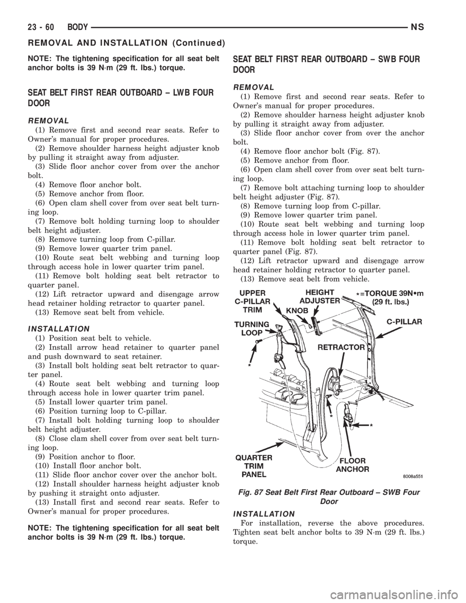
(4) Remove floor anchor bolt (Fig. 87).
(5) Remove anchor from floor.
(6) Open clam shell cover from over seat belt turn-
ing loop.
(7) Remove bolt attaching turning loop to shoulder
belt height adjuster (Fig. 87).
(8) Remove turning loop from C-pillar.
(9) Remove lower quarter trim panel.
(10) Route seat belt webbing and turning loop
through access hole in lower quarter trim panel.
(11) Remove bolt holding seat belt retractor to
quarter panel (Fig. 87).
(12) Lift retractor upward and disengage arrow
head retainer holding retractor to quarter panel.
(13) Remove seat belt from vehicle.
INSTALLATION
For installation, reverse the above procedures.
Tighten seat belt anchor bolts to 39 N´m (29 ft. lbs.)
torque.
Fig. 87 Seat Belt First Rear Outboard ± SWB Four
Door
23 - 60 BODYNS
REMOVAL AND INSTALLATION (Continued)
Page 1791 of 1938
SEAT BELT LEFT FIRST REAR OUTBOARD ± LWB
THREE DOOR
REMOVAL
(1) Remove first and second rear seats. Refer to
Owner's manual for proper procedures.
(2) Remove shoulder harness height adjuster knob
by pulling it straight away from adjuster.
(3) Slide floor anchor cover from over the anchor
bolt.
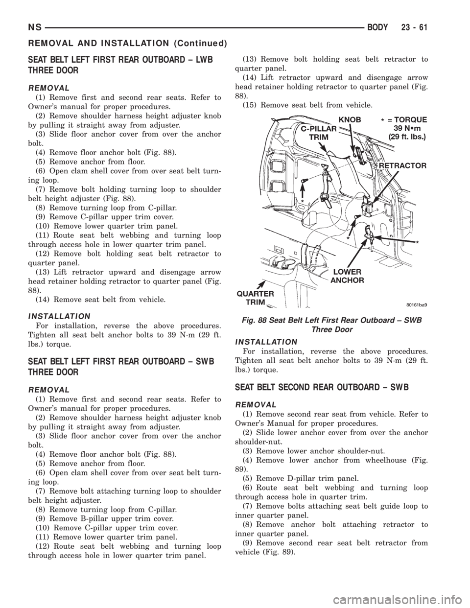
(4) Remove floor anchor bolt (Fig. 88).
(5) Remove anchor from floor.
(6) Open clam shell cover from over seat belt turn-
ing loop.
(7) Remove bolt holding turning loop to shoulder
belt height adjuster (Fig. 88).
(8) Remove turning loop from C-pillar.
(9) Remove C-pillar upper trim cover.
(10) Remove lower quarter trim panel.
(11) Route seat belt webbing and turning loop
through access hole in lower quarter trim panel.
(12) Remove bolt holding seat belt retractor to
quarter panel.
(13) Lift retractor upward and disengage arrow
head retainer holding retractor to quarter panel (Fig.
88).
(14) Remove seat belt from vehicle.
INSTALLATION
For installation, reverse the above procedures.
Tighten all seat belt anchor bolts to 39 N´m (29 ft.
lbs.) torque.
SEAT BELT LEFT FIRST REAR OUTBOARD ± SWB
THREE DOOR
REMOVAL
(1) Remove first and second rear seats. Refer to
Owner's manual for proper procedures.
(2) Remove shoulder harness height adjuster knob
by pulling it straight away from adjuster.
(3) Slide floor anchor cover from over the anchor
bolt.
(4) Remove floor anchor bolt (Fig. 88).
(5) Remove anchor from floor.
(6) Open clam shell cover from over seat belt turn-
ing loop.
(7) Remove bolt attaching turning loop to shoulder
belt height adjuster.
(8) Remove turning loop from C-pillar.
(9) Remove B-pillar upper trim cover.
(10) Remove C-pillar upper trim cover.
(11) Remove lower quarter trim panel.
(12) Route seat belt webbing and turning loop
through access hole in lower quarter trim panel.(13) Remove bolt holding seat belt retractor to
quarter panel.
(14) Lift retractor upward and disengage arrow
head retainer holding retractor to quarter panel (Fig.
88).
(15) Remove seat belt from vehicle.
INSTALLATION
For installation, reverse the above procedures.
Tighten all seat belt anchor bolts to 39 N´m (29 ft.
lbs.) torque.
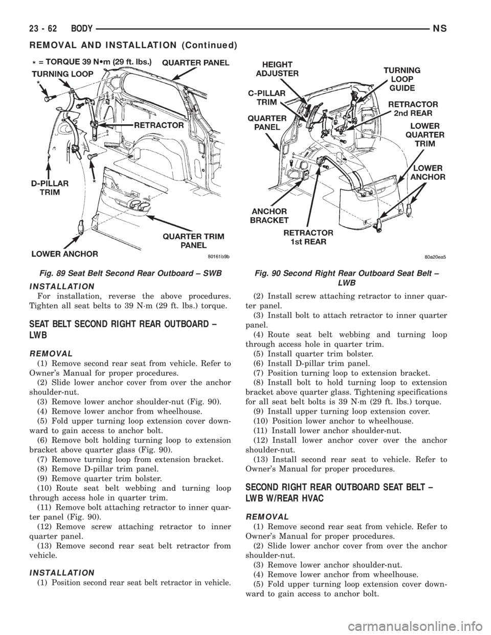
SEAT BELT SECOND REAR OUTBOARD ± SWB
REMOVAL
(1) Remove second rear seat from vehicle. Refer to
Owner's Manual for proper procedures.
(2) Slide lower anchor cover from over the anchor
shoulder-nut.
(3) Remove lower anchor shoulder-nut.
(4) Remove lower anchor from wheelhouse (Fig.
89).
(5) Remove D-pillar trim panel.
(6) Route seat belt webbing and turning loop
through access hole in quarter trim.
(7) Remove bolts attaching seat belt guide loop to
inner quarter panel.
(8) Remove anchor bolt attaching retractor to
inner quarter panel.
(9) Remove second rear seat belt retractor from
vehicle (Fig. 89).
Fig. 88 Seat Belt Left First Rear Outboard ± SWB
Three Door
NSBODY 23 - 61
REMOVAL AND INSTALLATION (Continued)
Page 1792 of 1938
INSTALLATION
For installation, reverse the above procedures.
Tighten all seat belts to 39 N´m (29 ft. lbs.) torque.
SEAT BELT SECOND RIGHT REAR OUTBOARD ±
LW B
REMOVAL
(1) Remove second rear seat from vehicle. Refer to
Owner's Manual for proper procedures.
(2) Slide lower anchor cover from over the anchor
shoulder-nut.
(3) Remove lower anchor shoulder-nut (Fig. 90).
(4) Remove lower anchor from wheelhouse.
(5) Fold upper turning loop extension cover down-
ward to gain access to anchor bolt.
(6) Remove bolt holding turning loop to extension
bracket above quarter glass (Fig. 90).
(7) Remove turning loop from extension bracket.
(8) Remove D-pillar trim panel.
(9) Remove quarter trim bolster.
(10) Route seat belt webbing and turning loop
through access hole in quarter trim.
(11) Remove bolt attaching retractor to inner quar-
ter panel (Fig. 90).
(12) Remove screw attaching retractor to inner
quarter panel.
(13) Remove second rear seat belt retractor from
vehicle.
INSTALLATION
(1) Position second rear seat belt retractor in vehicle.
(2) Install screw attaching retractor to inner quar-
ter panel.
(3) Install bolt to attach retractor to inner quarter
panel.
(4) Route seat belt webbing and turning loop
through access hole in quarter trim.
(5) Install quarter trim bolster.
(6) Install D-pillar trim panel.
(7) Position turning loop to extension bracket.
(8) Install bolt to hold turning loop to extension
bracket above quarter glass. Tightening specifications
for all seat belt bolts is 39 N´m (29 ft. lbs.) torque.
(9) Install upper turning loop extension cover.
(10) Position lower anchor to wheelhouse.
(11) Install lower anchor shoulder-nut.
(12) Install lower anchor cover over the anchor
shoulder-nut.
(13) Install second rear seat to vehicle. Refer to
Owner's Manual for proper procedures.
SECOND RIGHT REAR OUTBOARD SEAT BELT ±
LWB W/REAR HVAC
REMOVAL
(1) Remove second rear seat from vehicle. Refer to
Owner's Manual for proper procedures.
(2) Slide lower anchor cover from over the anchor
shoulder-nut.
(3) Remove lower anchor shoulder-nut.
(4) Remove lower anchor from wheelhouse.
(5) Fold upper turning loop extension cover down-
ward to gain access to anchor bolt.
Fig. 89 Seat Belt Second Rear Outboard ± SWBFig. 90 Second Right Rear Outboard Seat Belt ±
LW B
23 - 62 BODYNS
REMOVAL AND INSTALLATION (Continued)
Page 1794 of 1938
SHOULDER BELT HEIGHT ADJUSTER±BOR
C-PILLAR
REMOVAL
(1) Remove B or C-pillar trim cover.
(2) Remove screws holding shoulder belt height
adjuster to pillar.
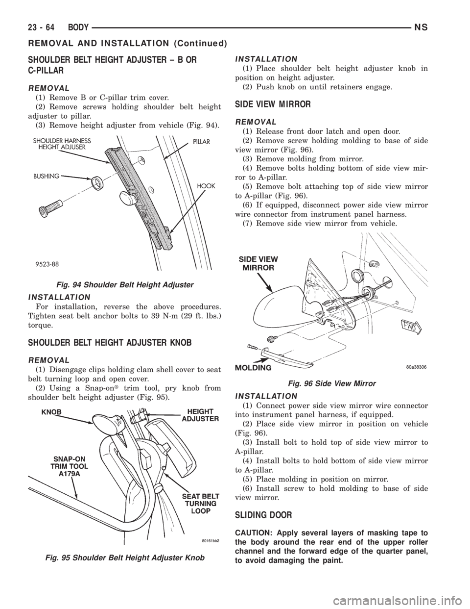
(3) Remove height adjuster from vehicle (Fig. 94).
INSTALLATION
For installation, reverse the above procedures.
Tighten seat belt anchor bolts to 39 N´m (29 ft. lbs.)
torque.
SHOULDER BELT HEIGHT ADJUSTER KNOB
REMOVAL
(1) Disengage clips holding clam shell cover to seat
belt turning loop and open cover.
(2) Using a Snap-onttrim tool, pry knob from
shoulder belt height adjuster (Fig. 95).
INSTALLATION
(1) Place shoulder belt height adjuster knob in
position on height adjuster.
(2) Push knob on until retainers engage.
SIDE VIEW MIRROR
REMOVAL
(1) Release front door latch and open door.
(2) Remove screw holding molding to base of side
view mirror (Fig. 96).
(3) Remove molding from mirror.
(4) Remove bolts holding bottom of side view mir-
ror to A-pillar.
(5) Remove bolt attaching top of side view mirror
to A-pillar (Fig. 96).
(6) If equipped, disconnect power side view mirror
wire connector from instrument panel harness.
(7) Remove side view mirror from vehicle.
INSTALLATION
(1) Connect power side view mirror wire connector
into instrument panel harness, if equipped.
(2) Place side view mirror in position on vehicle
(Fig. 96).
(3) Install bolt to hold top of side view mirror to
A-pillar.
(4) Install bolts to hold bottom of side view mirror
to A-pillar.
(5) Place molding in position on mirror.
(6) Install screw to hold molding to base of side
view mirror.
SLIDING DOOR
CAUTION: Apply several layers of masking tape to
the body around the rear end of the upper roller
channel and the forward edge of the quarter panel,
to avoid damaging the paint.
Fig. 94 Shoulder Belt Height Adjuster
Fig. 95 Shoulder Belt Height Adjuster Knob
Fig. 96 Side View Mirror
23 - 64 BODYNS
REMOVAL AND INSTALLATION (Continued)