power steering fluid CHRYSLER VOYAGER 1996 Workshop Manual
[x] Cancel search | Manufacturer: CHRYSLER, Model Year: 1996, Model line: VOYAGER, Model: CHRYSLER VOYAGER 1996Pages: 1938, PDF Size: 55.84 MB
Page 1456 of 1938
NOTE: The next step must be done to allow the
removal of the steering gear from the front suspen-
sion cradle. The steering gear can not be removed
from the vehicle with the intermediate coupler
attached to the steering gear.
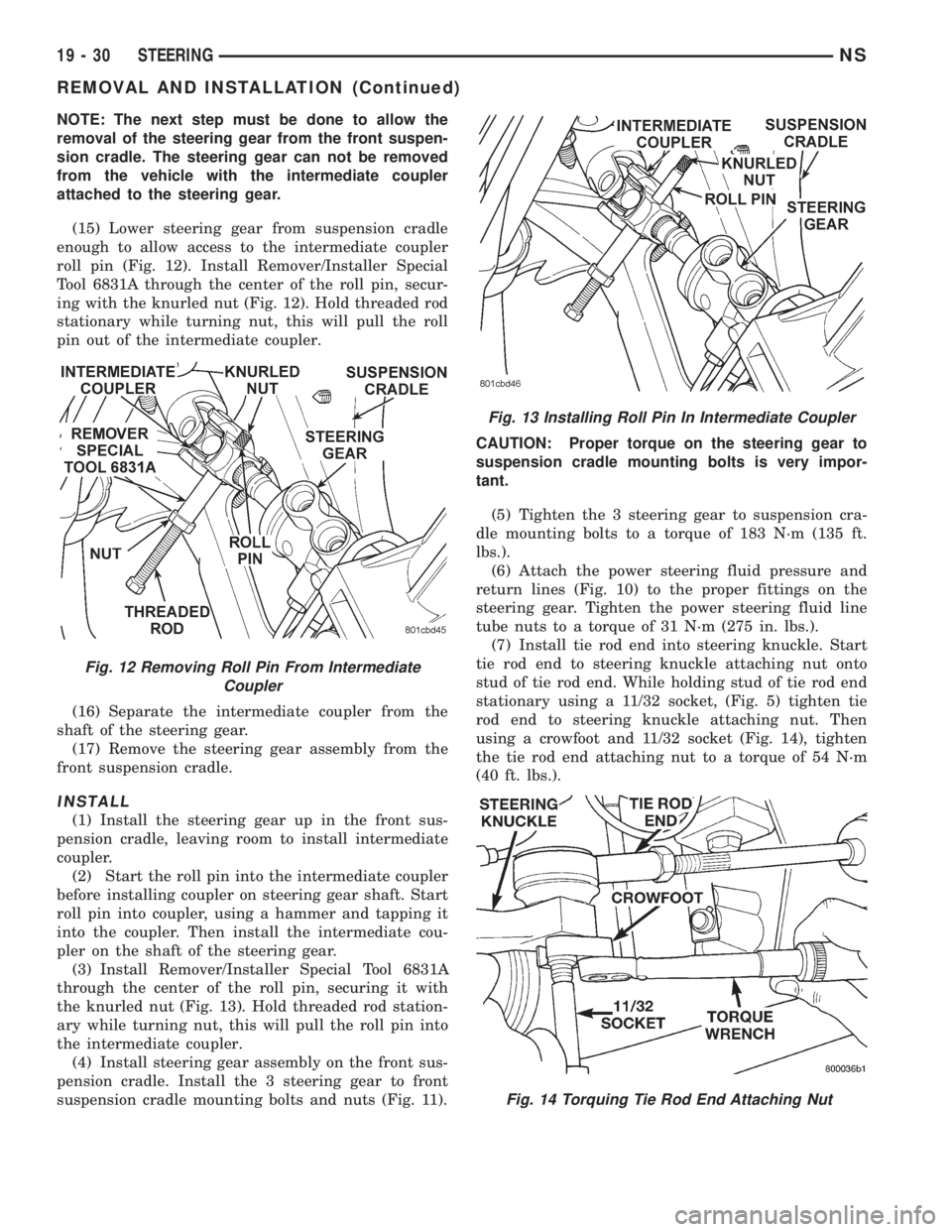
(15) Lower steering gear from suspension cradle
enough to allow access to the intermediate coupler
roll pin (Fig. 12). Install Remover/Installer Special
Tool 6831A through the center of the roll pin, secur-
ing with the knurled nut (Fig. 12). Hold threaded rod
stationary while turning nut, this will pull the roll
pin out of the intermediate coupler.
(16) Separate the intermediate coupler from the
shaft of the steering gear.
(17) Remove the steering gear assembly from the
front suspension cradle.
INSTALL
(1) Install the steering gear up in the front sus-
pension cradle, leaving room to install intermediate
coupler.
(2) Start the roll pin into the intermediate coupler
before installing coupler on steering gear shaft. Start
roll pin into coupler, using a hammer and tapping it
into the coupler. Then install the intermediate cou-
pler on the shaft of the steering gear.
(3) Install Remover/Installer Special Tool 6831A
through the center of the roll pin, securing it with
the knurled nut (Fig. 13). Hold threaded rod station-
ary while turning nut, this will pull the roll pin into
the intermediate coupler.
(4) Install steering gear assembly on the front sus-
pension cradle. Install the 3 steering gear to front
suspension cradle mounting bolts and nuts (Fig. 11).CAUTION: Proper torque on the steering gear to
suspension cradle mounting bolts is very impor-
tant.
(5) Tighten the 3 steering gear to suspension cra-
dle mounting bolts to a torque of 183 N´m (135 ft.
lbs.).
(6) Attach the power steering fluid pressure and
return lines (Fig. 10) to the proper fittings on the
steering gear. Tighten the power steering fluid line
tube nuts to a torque of 31 N´m (275 in. lbs.).
(7) Install tie rod end into steering knuckle. Start
tie rod end to steering knuckle attaching nut onto
stud of tie rod end. While holding stud of tie rod end
stationary using a 11/32 socket, (Fig. 5) tighten tie
rod end to steering knuckle attaching nut. Then
using a crowfoot and 11/32 socket (Fig. 14), tighten
the tie rod end attaching nut to a torque of 54 N´m
(40 ft. lbs.).
Fig. 12 Removing Roll Pin From Intermediate
Coupler
Fig. 13 Installing Roll Pin In Intermediate Coupler
Fig. 14 Torquing Tie Rod End Attaching Nut
19 - 30 STEERINGNS
REMOVAL AND INSTALLATION (Continued)
Page 1457 of 1938
CAUTION: Proper torque on the cradle plate to
suspension cradle mounting bolts is very impor-
tant.
(8) Install cradle plate on front suspension cradle
and install the 10 cradle plate to cradle attaching
bolts and nuts (Fig. 8). Tighten all attaching bolts to
a torque of 165 N´m (123 ft. lbs.).
(9) Install the bracket (Fig. 9) attaching the power
steering fluid tubes to the front suspension cradle.
CAUTION:
(10) Install the power steering fluid return hose on
the steel tube at the front suspension cradle (Fig. 4).
(11) Install a screw type hose clamp on the power
steering hose to steel tube connection.Be sure hose
clamp is installed on return tube past the upset
bead on the tube.Tighten the screw clamp to a
torque of 2 N´m (18 in. lbs.).
CAUTION: The protective heat shield sleeves must
cover the entire rubber hose and hose to tube con-
nection portion of both the power steering fluid
pressure and return hoses (Fig. 4). This is required
to prevent the power steering hoses from being
overheated.
(12) When used, properly position the protective
heat sleeves on the power steering hoses. Then, tie
strap the heat sleeves to the power steering hoses to
keep them in their proper position.
(13) Install the front tire and wheel assemblies on
vehicle. Install the wheel lug nuts and torque to 129
N´m (95 ft. lbs.).
(14) Lower the vehicle to a level were the interior
of vehicle is accessible.
(15) Using the intermediate coupler, turn the front
wheels of the vehicle to the left until the intermedi-
ate coupler shaft is properly aligned with the steer-
ing column coupler. Assemble the steering column
shaft coupler (Fig. 3) onto the steering gear interme-
diate coupler. Install steering column coupler to
intermediate shaft retaining pinch bolt (Fig. 3).
Tighten the pinch bolt nut to a torque of 28 N´m (250
in. lbs.).
CAUTION: Do not use automatic transmission fluid
in the power steering system. Only use Mopar,
Power Steering Fluid or an exact equivalent prod-
uct.
(16) Fill power steering pump fluid reservoir to the
proper level.
(17) Start the engine and let run for a few seconds.
Then turn the engine off.(18) Add fluid if necessary. Repeat the above pro-
cedure until the fluid level remains constant after
running the engine.
(19) Raise front wheels of vehicle off the ground.
(20) Start the engine. Slowly turn the steering
wheel right and left, lightly contacting the wheel
stops. Then turn the engine off.
(21) Add power steering fluid if necessary.
(22) Lower the vehicle and turn the steering wheel
slowly from lock to lock.
(23) Stop the engine. Check the fluid level and
refill as required.
(24) If the fluid is extremely foamy, allow the vehi-
cle to stand a few minutes and repeat the above pro-
cedure.
(25) Fill power steering reservoir to correct level
with Mopart, Power Steering Fluid, or equivalent.
(26) Adjust toe (Refer to Group 2 Suspension).
DISASSEMBLY AND ASSEMBLY
STEERING GEAR INNER TIE ROD BOOT
DISASSEMBLE
NOTE: The removal and installation of the inner tie
rod boot must be performed with the steering gear
assembly removed from the vehicle.
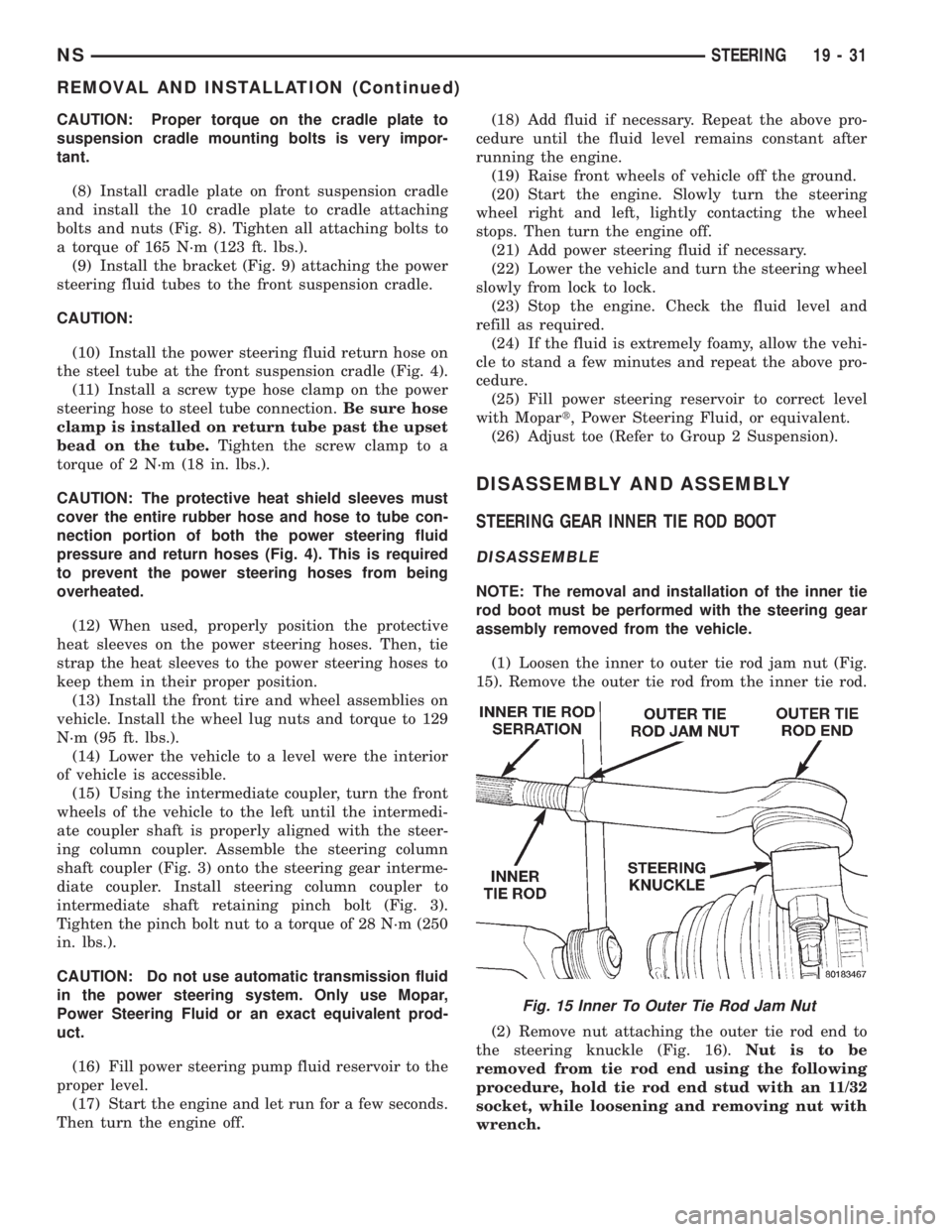
(1) Loosen the inner to outer tie rod jam nut (Fig.
15). Remove the outer tie rod from the inner tie rod.
(2) Remove nut attaching the outer tie rod end to
the steering knuckle (Fig. 16).Nut is to be
removed from tie rod end using the following
procedure, hold tie rod end stud with an 11/32
socket, while loosening and removing nut with
wrench.
Fig. 15 Inner To Outer Tie Rod Jam Nut
NSSTEERING 19 - 31
REMOVAL AND INSTALLATION (Continued)
Page 1473 of 1938
STEERING
CONTENTS
page
POWER STEERINGÐ2.5L VM DIESEL....... 1
POWER STEERINGÐ2.5L VM DIESEL
INDEX
page page
GENERAL INFORMATION
POWER STEERING GEAR................ 1
POWER STEERING PUMP................ 1
STEERING GEAR OPERATIONÐRHD & LHD
VEHICLES........................... 1SERVICE PROCEDURES
POWER STEERING PUMP ± INITIAL
OPERATION.......................... 1
REMOVAL AND INSTALLATION
POWER STEERING PUMPÐ2.5L DIESEL..... 2
GENERAL INFORMATION
POWER STEERING PUMP
The power steering pump used with the 2.5L VM
Diesel engine operates the same way as the power
steering pump used with the 2.5/4.0L gasoline
engines. Refer to the Description and Operation sec-
tion for the 2.5/4.0L gasoline engine power steering
pump for more information.
STEERING GEAR OPERATIONÐRHD & LHD
VEHICLES
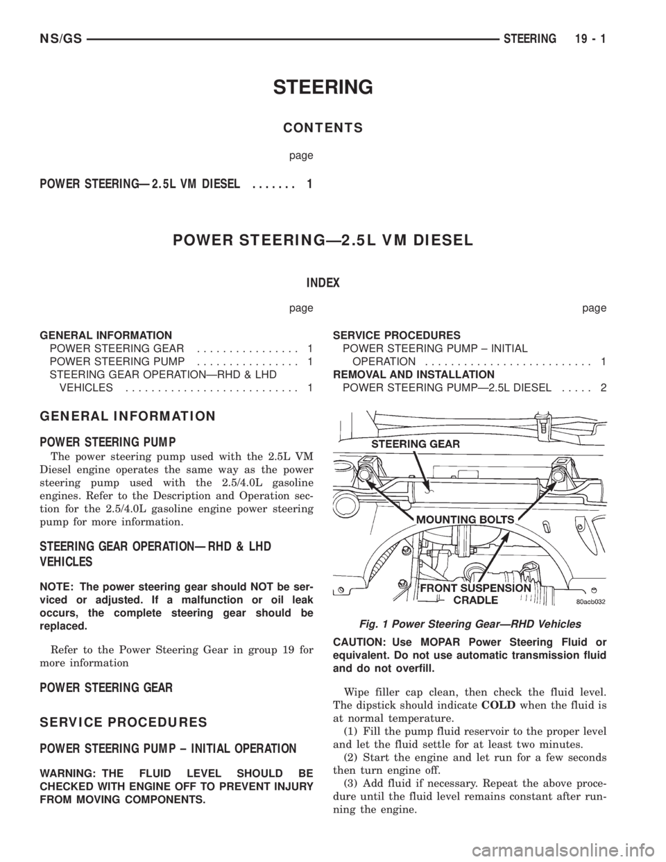
NOTE: The power steering gear should NOT be ser-
viced or adjusted. If a malfunction or oil leak
occurs, the complete steering gear should be
replaced.
Refer to the Power Steering Gear in group 19 for
more information
POWER STEERING GEAR
SERVICE PROCEDURES
POWER STEERING PUMP ± INITIAL OPERATION
WARNING: THE FLUID LEVEL SHOULD BE
CHECKED WITH ENGINE OFF TO PREVENT INJURY
FROM MOVING COMPONENTS.CAUTION: Use MOPAR Power Steering Fluid or
equivalent. Do not use automatic transmission fluid
and do not overfill.
Wipe filler cap clean, then check the fluid level.
The dipstick should indicateCOLDwhen the fluid is
at normal temperature.
(1) Fill the pump fluid reservoir to the proper level
and let the fluid settle for at least two minutes.
(2) Start the engine and let run for a few seconds
then turn engine off.
(3) Add fluid if necessary. Repeat the above proce-
dure until the fluid level remains constant after run-
ning the engine.
Fig. 1 Power Steering GearÐRHD Vehicles
NS/GSSTEERING 19 - 1
Page 1474 of 1938
(4) Raise the front wheels off the ground.
(5) Slowly turn the steering wheel right and left,
lightly contacting the wheel stops at least 20 times.
(6) Check the fluid level add if necessary.
(7) Lower the vehicle, start the engine and turn
the steering wheel slowly from lock to lock.
(8) Stop the engine and check the fluid level and
refill as required.
(9) If the fluid is extremely foamy or milky look-
ing, allow the vehicle to stand a few minutes and
repeat the procedure.
CAUTION: Do not run a vehicle with foamy fluid for
an extended period. This may cause pump damage.
REMOVAL AND INSTALLATION
POWER STEERING PUMPÐ2.5L DIESEL
NOTE: The power steering pump is mounted below
the fuel pump on the left side of the engine. The
vehicle should be raised on a hoist to access the
pump from below.
REMOVAL
(1) Remove serpentine drive belt. Refer to Group 7,
Cooling System, for procedure.
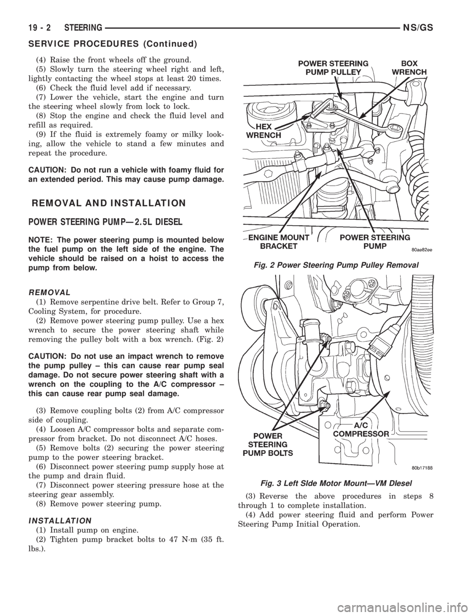
(2) Remove power steering pump pulley. Use a hex
wrench to secure the power steering shaft while
removing the pulley bolt with a box wrench. (Fig. 2)
CAUTION: Do not use an impact wrench to remove
the pump pulley ± this can cause rear pump seal
damage. Do not secure power steering shaft with a
wrench on the coupling to the A/C compressor ±
this can cause rear pump seal damage.
(3) Remove coupling bolts (2) from A/C compressor
side of coupling.
(4) Loosen A/C compressor bolts and separate com-
pressor from bracket. Do not disconnect A/C hoses.
(5) Remove bolts (2) securing the power steering
pump to the power steering bracket.
(6) Disconnect power steering pump supply hose at
the pump and drain fluid.
(7) Disconnect power steering pressure hose at the
steering gear assembly.
(8) Remove power steering pump.
INSTALLATION
(1) Install pump on engine.
(2) Tighten pump bracket bolts to 47 N´m (35 ft.
lbs.).(3) Reverse the above procedures in steps 8
through 1 to complete installation.
(4) Add power steering fluid and perform Power
Steering Pump Initial Operation.
Fig. 2 Power Steering Pump Pulley Removal
Fig. 3 Left SIde Motor MountÐVM DIesel
19 - 2 STEERINGNS/GS
SERVICE PROCEDURES (Continued)
Page 1478 of 1938
GEARSHIFT AND PARKING LOCK CONTROLS
The transaxle is controlled by a lever type gear-
shift incorporated within the steering column. The
control has six selector lever positions: P (park), R
(reverse), N (neutral), and D (drive), 2 (second), and
1 (first). The parking lock is applied by moving the
selector lever past a gate to the P position.Do not
apply the parking lock until the vehicle has
stopped; otherwise, a severe ratchet noise will
occur.
TORQUE CONVERTER CLUTCH SOLENOID WIRING
CONNECTOR
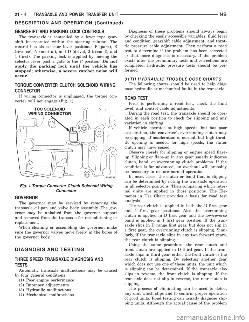
If wiring connector is unplugged, the torque con-
verter will not engage (Fig. 1) .
GOVERNOR
The governor may be serviced by removing the
transaxle oil pan and valve body assembly. The gov-
ernor may be unbolted from the governor support
and removed from the transaxle for reconditioning or
replacement.
When cleaning or assembling the governor, make
sure the governor valves move freely in the bores of
the governor body.
DIAGNOSIS AND TESTING
THREE SPEED TRANSAXLE DIAGNOSIS AND
TESTS
Automatic transaxle malfunctions may be caused
by four general conditions:
(1) Poor engine performance
(2) Improper adjustments
(3) Hydraulic malfunctions
(4) Mechanical malfunctionsDiagnosis of these problems should always begin
by checking the easily accessible variables; fluid level
and condition, gearshift cable adjustment, and throt-
tle pressure cable adjustment. Then perform a road
test to determine if the problem has been corrected
or that more diagnosis is necessary. If the problem
exists after the preliminary tests and corrections are
completed, hydraulic pressure tests should be per-
formed
31TH HYDRAULIC TROUBLE CODE CHARTS
The following charts should be used to help diag-
nose hydraulic or mechanical faults in the transaxle .
ROAD TEST
Prior to performing a road test, check the fluid
level, and control cable adjustments.
During the road test, the transaxle should be oper-
ated in each position to check for slipping and any
variation in shifting.
If vehicle operates at high speeds, but has poor
acceleration, the converter's overrunning clutch may
be slipping. If acceleration is normal, but high throt-
tle opening is needed for high speeds, the stator
clutch may have seized.
Observe closely for slipping or engine speed flare-
up. Slipping or flare-up in any gear usually indicates
clutch, band, or overrunning clutch problems. If the
condition is far advanced, an overhaul will probably
be necessary to restore normal operation.
In most cases, the clutch or band that is slipping
can be determined by noting the transaxle operation
in all selector positions. Then comparing which inter-
nal units are applied in those positions. The Ele-
ments in Use Chart provides a basis for road test
analysis .
The rear clutch is applied in both the D first gear
and 1 first gear positions. Also the overrunning
clutch is applied in D first gear and the low/reverse
band is applied in 1 first gear position. If the tran-
saxle slips in D range first gear, but does not slip in
1 first gear, the overrunning clutch is slipping. Simi-
larly, if the transaxle slips in any two forward gears,
the rear clutch is slipping.
Using the same procedure, the rear clutch and
front clutch are applied in D third gear. If the tran-
saxle slips in third gear, either the front clutch or the
rear clutch is slipping. By selecting another gear
which does not use one of those units, the unit which
is slipping can be determined. If the transaxle also
slips in reverse, the front clutch is slipping. If the
transaxle does not slip in reverse, the rear clutch is
slipping.
The process of eliminating can be used to detect
any unit which slips and to confirm proper operation
of good units. Road testing can usually diagnose slip-
ping units. Although the actual cause of the problem
Fig. 1 Torque Converter Clutch Solenoid Wiring
Connector
21 - 4 TRANSAXLE AND POWER TRANSFER UNITNS
DESCRIPTION AND OPERATION (Continued)
Page 1548 of 1938
TORQUE MANAGEMENT
Most 41TE transaxles utilize torque management.
Torque management is a unique function of the Pow-
ertrain Control Module (PCM). The PCM receives
output signals from the Transmission Control Module
(TCM) and many various engine sensors. The PCM
evaluates these signals and decides if it is necessary
to decrease the output of the engine's torque. This
reduction in torque does not interfere with the nor-
mal operation of the vehicle. This reduction in torque
will prolong the life of the drivetrain components.
Torque reduction is not noticeable in normal driving
functions. The torque reduction function shuts off
above 16 MPH.
ON-BOARD DIAGNOSTICS
This vehicle utilizes a diagnostic system called
OBDII. The powertrain control module communicates
with the Transmission Control Module. Whenever
the transaxle sets a fault in the Transmission Con-
trol Module (dependent on which fault is set), the
powertrain control module will turn on a MIL (Mal-
function Indicator Lamp) on the instrument cluster.
By reading the code in the powertrain control module
it will tell you where the fault occurred. If the fault
occurred in the transaxle, the controller will read a
CODE 45.For further information regarding OBDII,
refer to Group 25, Emission Systems.
These controls provide comprehensive, on-board
transaxle diagnostics. The information available can
aid in transaxle diagnosis. For example, apply ele-
ment buildup rate indicates solenoid performance.
Also included are self diagnostic functions. Self diag-
nostics allow the technician to test the condition of
the electronic controls. The Transmission Control
Module continuously monitors its critical functions. It
also records any malfunctions, and the number of
engine starts since the last malfunction. This allows
the technician to use the information in the event of
a customer complaint.
TRANSMISSION CONTROL MODULE
Do not interchange Transmission Control Modules
with previous year transmission control modules. If a
same year TCM is being used from a different vehi-
cle, the following procedures must be performed:
²Quick Learn Procedure
²Electronic Pinion Factor Procedure
The Transmission Control Module is located on the
right inner fender panel, in the engine compartment.
It is held in place by four mounting screws.NOTE: If the Transmission Control Module has
been replaced, the following procedures must be
performed:
²Quick Learn Procedure: This procedure will
allow the transmission control module to learn the
characteristics of the vehicle.
²Electronic Pinion Factor Procedure: This proce-
dure will reprogram the TCM to compensate for dif-
ferent tire sizes and final drive ratios.
GEARSHIFT AND PARKING LOCK CONTROLS
The transaxle is controlled by a lever type gear-
shift incorporated within the steering column. The
control has six selector lever positions: P (park), R
(reverse), N (neutral), and D (drive), 2 (second), and
1 (first). The parking lock is applied by moving the
selector lever past a gate to the P position.Do not
apply the parking lock until the vehicle has
stopped; otherwise, a severe ratchet noise will
occur.
TRANSMISSION RANGE SENSOR
The 41TE transaxle is equipped with a transmis-
sion range sensor that is located on top of the valve
body. This sensor will allow for accurate transmission
gear position measurement.
To service the transmission range sensor (TRS),
you must remove the valve body. For repair proce-
dures, refer to the Removal and Installation section
within this group.
Also located within the TRS is a transmission tem-
perature sensor. This sensor is used to measure the
transmission fluid sump temperature. The transmis-
sion temperature sensor is serviced with the TRS as
a unit.
SHIFT POSITION INDICATOR
The shifter position indicator is located in the
instrument cluster. The shifter position indicator out-
lines with a box the gear position the transaxle man-
ual valve lever is in.
The transmission range sensor (located on the
valvebody) sends a signal to the TCM on the position
of the transaxle manual valve lever. The TCM
receives the switch signal and processes the data.
The TCM sends the Shift Lever Position (SLP) infor-
mation to the BCM via the CCD bus. The BCM then
outlines with a box the appropriate shifter position
indicator in the instrument cluster.
To replace the shifter position indicator, refer to
Group 8E, Instrument Panel And Gauges.
21 - 74 TRANSAXLE AND POWER TRANSFER UNITNS
DESCRIPTION AND OPERATION (Continued)