ESP CHRYSLER VOYAGER 1996 Repair Manual
[x] Cancel search | Manufacturer: CHRYSLER, Model Year: 1996, Model line: VOYAGER, Model: CHRYSLER VOYAGER 1996Pages: 1938, PDF Size: 55.84 MB
Page 1907 of 1938
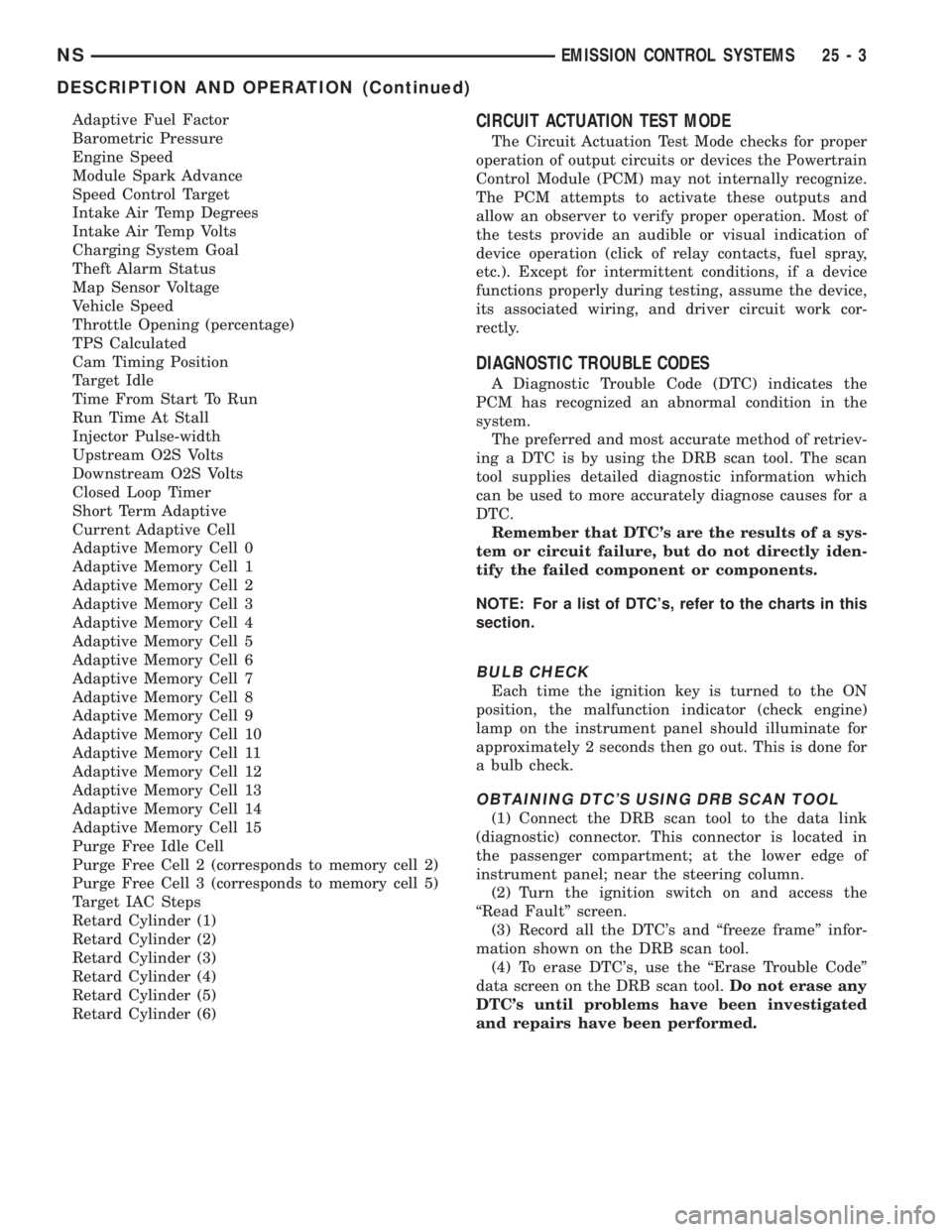
Adaptive Fuel Factor
Barometric Pressure
Engine Speed
Module Spark Advance
Speed Control Target
Intake Air Temp Degrees
Intake Air Temp Volts
Charging System Goal
Theft Alarm Status
Map Sensor Voltage
Vehicle Speed
Throttle Opening (percentage)
TPS Calculated
Cam Timing Position
Target Idle
Time From Start To Run
Run Time At Stall
Injector Pulse-width
Upstream O2S Volts
Downstream O2S Volts
Closed Loop Timer
Short Term Adaptive
Current Adaptive Cell
Adaptive Memory Cell 0
Adaptive Memory Cell 1
Adaptive Memory Cell 2
Adaptive Memory Cell 3
Adaptive Memory Cell 4
Adaptive Memory Cell 5
Adaptive Memory Cell 6
Adaptive Memory Cell 7
Adaptive Memory Cell 8
Adaptive Memory Cell 9
Adaptive Memory Cell 10
Adaptive Memory Cell 11
Adaptive Memory Cell 12
Adaptive Memory Cell 13
Adaptive Memory Cell 14
Adaptive Memory Cell 15
Purge Free Idle Cell
Purge Free Cell 2 (corresponds to memory cell 2)
Purge Free Cell 3 (corresponds to memory cell 5)
Target IAC Steps
Retard Cylinder (1)
Retard Cylinder (2)
Retard Cylinder (3)
Retard Cylinder (4)
Retard Cylinder (5)
Retard Cylinder (6)CIRCUIT ACTUATION TEST MODE
The Circuit Actuation Test Mode checks for proper
operation of output circuits or devices the Powertrain
Control Module (PCM) may not internally recognize.
The PCM attempts to activate these outputs and
allow an observer to verify proper operation. Most of
the tests provide an audible or visual indication of
device operation (click of relay contacts, fuel spray,
etc.). Except for intermittent conditions, if a device
functions properly during testing, assume the device,
its associated wiring, and driver circuit work cor-
rectly.
DIAGNOSTIC TROUBLE CODES
A Diagnostic Trouble Code (DTC) indicates the
PCM has recognized an abnormal condition in the
system.
The preferred and most accurate method of retriev-
ing a DTC is by using the DRB scan tool. The scan
tool supplies detailed diagnostic information which
can be used to more accurately diagnose causes for a
DTC.
Remember that DTC's are the results of a sys-
tem or circuit failure, but do not directly iden-
tify the failed component or components.
NOTE: For a list of DTC's, refer to the charts in this
section.
BULB CHECK
Each time the ignition key is turned to the ON
position, the malfunction indicator (check engine)
lamp on the instrument panel should illuminate for
approximately 2 seconds then go out. This is done for
a bulb check.
OBTAINING DTC'S USING DRB SCAN TOOL
(1) Connect the DRB scan tool to the data link
(diagnostic) connector. This connector is located in
the passenger compartment; at the lower edge of
instrument panel; near the steering column.
(2) Turn the ignition switch on and access the
ªRead Faultº screen.
(3) Record all the DTC's and ªfreeze frameº infor-
mation shown on the DRB scan tool.
(4) To erase DTC's, use the ªErase Trouble Codeº
data screen on the DRB scan tool.Do not erase any
DTC's until problems have been investigated
and repairs have been performed.
NSEMISSION CONTROL SYSTEMS 25 - 3
DESCRIPTION AND OPERATION (Continued)
Page 1908 of 1938
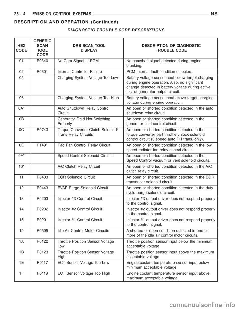
DIAGNOSTIC TROUBLE CODE DESCRIPTIONS
HEX
CODEGENERIC
SCAN
TOOL
CODEDRB SCAN TOOL
DISPLAYDESCRIPTION OF DIAGNOSTIC
TROUBLE CODE
01 P0340 No Cam Signal at PCM No camshaft signal detected during engine
cranking.
02 P0601 Internal Controller Failure PCM Internal fault condition detected.
05 Charging System Voltage Too Low Battery voltage sense input below target charging
during engine operation. Also, no significant
change detected in battery voltage during active
test of generator output circuit.
06 Charging System Voltage Too High Battery voltage sense input above target charging
voltage during engine operation.
0A* Auto Shutdown Relay Control
CircuitAn open or shorted condition detected in the auto
shutdown relay circuit.
0B Generator Field Not Switching
ProperlyAn open or shorted condition detected in the
generator field control circuit.
0C P0743 Torque Converter Clutch Soleniod/
Trans Relay CircuitsAn open or shorted condition detected in the
torque converter part throttle unlock solenoid
control circuit (3 speed auto RH trans. only).
0E P1491 Rad Fan Control Relay Circuit An open or shorted condition detected in the low
speed radiator fan relay control circuit.
0F* Speed Control Solenoid Circuits An open or shorted condition detected in the
Speed Control vacuum or vent solenoid circuits.
10* A/C Clutch Relay Circuit An open or shorted condition detected in the A/C
clutch relay circuit.
11 P0403 EGR Solenoid Circuit An open or shorted condition detected in the EGR
transducer solenoid circuit.
12 P0443 EVAP Purge Solenoid Circuit An open or shorted condition detected in the duty
cycle purge solenoid circuit.
13 P0203 Injector #3 Control Circuit Injector #3 output driver does not respond properly
to the control signal.
14 P0202 Injector #2 Control Circuit Injector #2 output driver does not respond properly
to the control signal.
15 P0201 Injector #1 Control Circuit Injector #1 output driver does not respond properly
to the control signal.
19 P0505 Idle Air Control Motor Circuits A shorted or open condition detected in one or
more of the idle air control motor circuits.
1A P0122 Throttle Position Sensor Voltage
LowThrottle position sensor input below the minimum
acceptable voltage
1B P0123 Throttle Position Sensor Voltage
HighThrottle position sensor input above the maximum
acceptable voltage.
1E P0117 ECT Sensor Voltage Too Low Engine coolant temperature sensor input below
minimum acceptable voltage.
1F P0118 ECT Sensor Voltage Too High Engine coolant temperature sensor input above
maximum acceptable voltage.
25 - 4 EMISSION CONTROL SYSTEMSNS
DESCRIPTION AND OPERATION (Continued)
Page 1909 of 1938
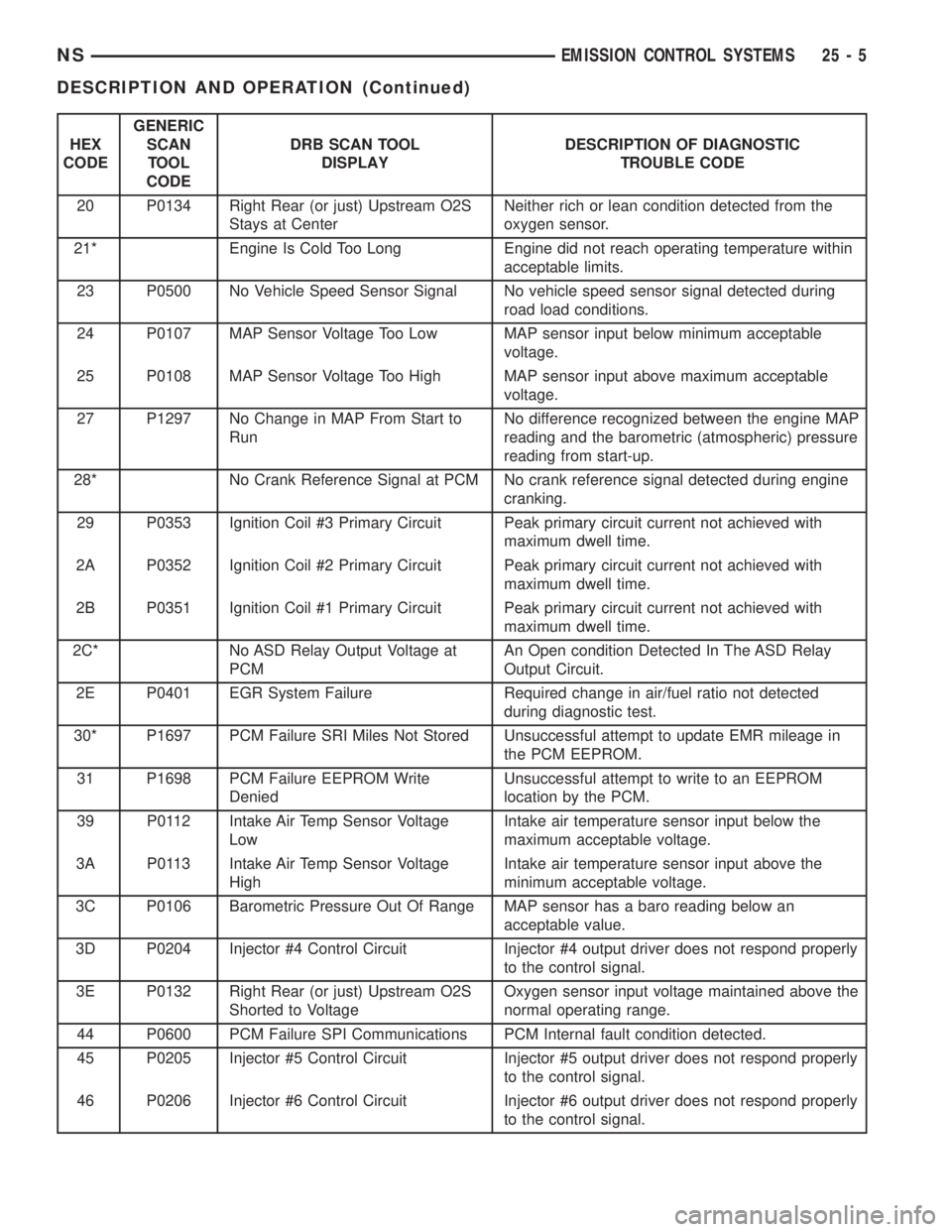
HEX
CODEGENERIC
SCAN
TOOL
CODEDRB SCAN TOOL
DISPLAYDESCRIPTION OF DIAGNOSTIC
TROUBLE CODE
20 P0134 Right Rear (or just) Upstream O2S
Stays at CenterNeither rich or lean condition detected from the
oxygen sensor.
21* Engine Is Cold Too Long Engine did not reach operating temperature within
acceptable limits.
23 P0500 No Vehicle Speed Sensor Signal No vehicle speed sensor signal detected during
road load conditions.
24 P0107 MAP Sensor Voltage Too Low MAP sensor input below minimum acceptable
voltage.
25 P0108 MAP Sensor Voltage Too High MAP sensor input above maximum acceptable
voltage.
27 P1297 No Change in MAP From Start to
RunNo difference recognized between the engine MAP
reading and the barometric (atmospheric) pressure
reading from start-up.
28* No Crank Reference Signal at PCM No crank reference signal detected during engine
cranking.
29 P0353 Ignition Coil #3 Primary Circuit Peak primary circuit current not achieved with
maximum dwell time.
2A P0352 Ignition Coil #2 Primary Circuit Peak primary circuit current not achieved with
maximum dwell time.
2B P0351 Ignition Coil #1 Primary Circuit Peak primary circuit current not achieved with
maximum dwell time.
2C* No ASD Relay Output Voltage at
PCMAn Open condition Detected In The ASD Relay
Output Circuit.
2E P0401 EGR System Failure Required change in air/fuel ratio not detected
during diagnostic test.
30* P1697 PCM Failure SRI Miles Not Stored Unsuccessful attempt to update EMR mileage in
the PCM EEPROM.
31 P1698 PCM Failure EEPROM Write
DeniedUnsuccessful attempt to write to an EEPROM
location by the PCM.
39 P0112 Intake Air Temp Sensor Voltage
LowIntake air temperature sensor input below the
maximum acceptable voltage.
3A P0113 Intake Air Temp Sensor Voltage
HighIntake air temperature sensor input above the
minimum acceptable voltage.
3C P0106 Barometric Pressure Out Of Range MAP sensor has a baro reading below an
acceptable value.
3D P0204 Injector #4 Control Circuit Injector #4 output driver does not respond properly
to the control signal.
3E P0132 Right Rear (or just) Upstream O2S
Shorted to VoltageOxygen sensor input voltage maintained above the
normal operating range.
44 P0600 PCM Failure SPI Communications PCM Internal fault condition detected.
45 P0205 Injector #5 Control Circuit Injector #5 output driver does not respond properly
to the control signal.
46 P0206 Injector #6 Control Circuit Injector #6 output driver does not respond properly
to the control signal.
NSEMISSION CONTROL SYSTEMS 25 - 5
DESCRIPTION AND OPERATION (Continued)
Page 1910 of 1938
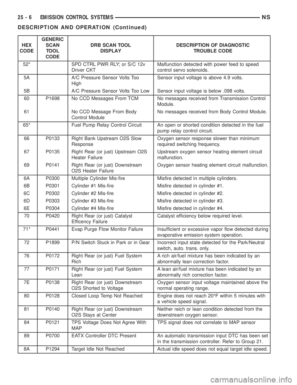
HEX
CODEGENERIC
SCAN
TOOL
CODEDRB SCAN TOOL
DISPLAYDESCRIPTION OF DIAGNOSTIC
TROUBLE CODE
52* SPD CTRL PWR RLY; or S/C 12v
Driver CKTMalfunction detected with power feed to speed
control servo solenoids.
5A A/C Pressure Sensor Volts Too
HighSensor input voltage is above 4.9 volts.
5B A/C Pressure Sensor Volts Too Low Sensor input voltage is below .098 volts.
60 P1698 No CCD Messages From TCM No messages received from Transmission Control
Module.
61 No CCD Message From Body
Control ModuleNo messages received from Body Control Module.
65* Fuel Pump Relay Control Circuit An open or shorted condition detected in the fuel
pump relay control circuit.
66 P0133 Right Bank Upstream O2S Slow
ResponseOxygen sensor response slower than minimum
required switching frequency.
67 P0135 Right Rear (or just) Upstream O2S
Heater FailureUpstream oxygen sensor heating element circuit
malfunction.
69 P0141 Right Rear (or just) Downstream
O2S Heater FailureOxygen sensor heating element circuit malfunction.
6A P0300 Multiple Cylinder Mis-fire Misfire detected in multiple cylinders.
6B P0301 Cylinder #1 Mis-fire Misfire detected in cylinder #1.
6C P0302 Cylinder #2 Mis-fire Misfire detected in cylinder #2.
6D P0303 Cylinder #3 Mis-fire Misfire detected in cylinder #3.
6E P0304 Cylinder #4 Mis-fire Misfire detected in cylinder #4.
70 P0420 Right Rear (or just) Catalyst
Efficency FailureCatalyst efficiency below required level.
71* P0441 Evap Purge Flow Monitor Failure Insufficient or excessive vapor flow detected during
evaporative emission system operation.
72 P1899 P/N Switch Stuck in Park or in Gear Incorrect input state detected for the Park/Neutral
switch, auto. trans. only.
76 P0172 Right Rear (or just) Fuel System
RichA rich air/fuel mixture has been indicated by an
abnormally lean correction factor.
77 P0171 Right Rear (or just) Fuel System
LeanA lean air/fuel mixture has been indicated by an
abnormally rich correction factor.
7E P0138 Right Rear (or just) Downstream
O2S Shorted to VoltageOxygen sensor input voltage maintained above the
normal operating range.
80 P0128 Closed Loop Temp Not Reached Engine does not reach 20ÉF within 5 minutes with
a vehicle speed signal.
81 P0140 Right Rear (or just) Downstream
O2S Stays at CenterNeither reich or lean condition detected from the
downstream oxygen sensor.
84 P0121 TPS Voltage Does Not Agree With
MAPTPS signal does not correlate to MAP sensor
89 P0700 EATX Controller DTC Present An automatic transmission input DTC has been set
in the transmission controller. Refer to Group 21.
8A P1294 Target Idle Not Reached Actual idle speed does not equal target idle speed.
25 - 6 EMISSION CONTROL SYSTEMSNS
DESCRIPTION AND OPERATION (Continued)
Page 1911 of 1938
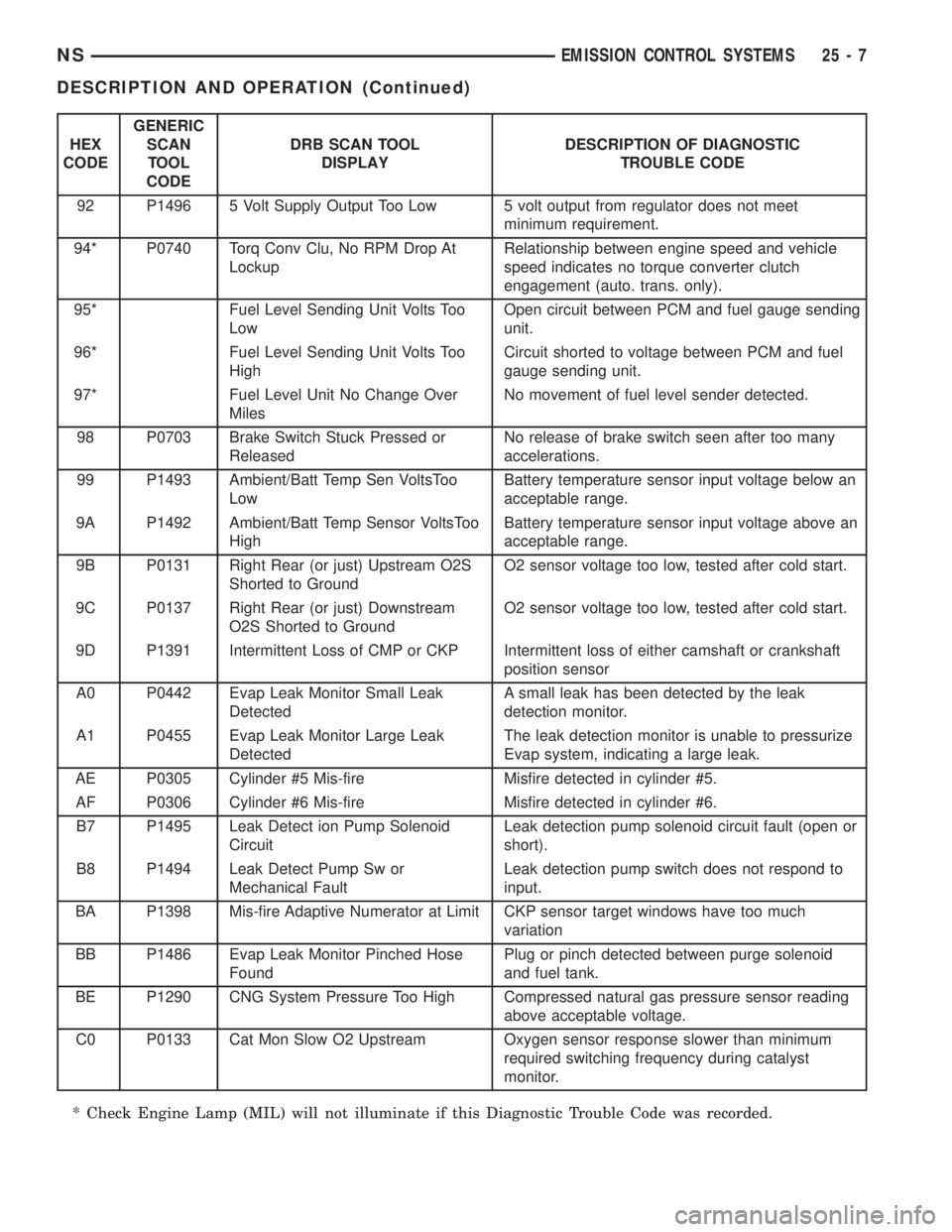
HEX
CODEGENERIC
SCAN
TOOL
CODEDRB SCAN TOOL
DISPLAYDESCRIPTION OF DIAGNOSTIC
TROUBLE CODE
92 P1496 5 Volt Supply Output Too Low 5 volt output from regulator does not meet
minimum requirement.
94* P0740 Torq Conv Clu, No RPM Drop At
LockupRelationship between engine speed and vehicle
speed indicates no torque converter clutch
engagement (auto. trans. only).
95* Fuel Level Sending Unit Volts Too
LowOpen circuit between PCM and fuel gauge sending
unit.
96* Fuel Level Sending Unit Volts Too
HighCircuit shorted to voltage between PCM and fuel
gauge sending unit.
97* Fuel Level Unit No Change Over
MilesNo movement of fuel level sender detected.
98 P0703 Brake Switch Stuck Pressed or
ReleasedNo release of brake switch seen after too many
accelerations.
99 P1493 Ambient/Batt Temp Sen VoltsToo
LowBattery temperature sensor input voltage below an
acceptable range.
9A P1492 Ambient/Batt Temp Sensor VoltsToo
HighBattery temperature sensor input voltage above an
acceptable range.
9B P0131 Right Rear (or just) Upstream O2S
Shorted to GroundO2 sensor voltage too low, tested after cold start.
9C P0137 Right Rear (or just) Downstream
O2S Shorted to GroundO2 sensor voltage too low, tested after cold start.
9D P1391 Intermittent Loss of CMP or CKP Intermittent loss of either camshaft or crankshaft
position sensor
A0 P0442 Evap Leak Monitor Small Leak
DetectedA small leak has been detected by the leak
detection monitor.
A1 P0455 Evap Leak Monitor Large Leak
DetectedThe leak detection monitor is unable to pressurize
Evap system, indicating a large leak.
AE P0305 Cylinder #5 Mis-fire Misfire detected in cylinder #5.
AF P0306 Cylinder #6 Mis-fire Misfire detected in cylinder #6.
B7 P1495 Leak Detect ion Pump Solenoid
CircuitLeak detection pump solenoid circuit fault (open or
short).
B8 P1494 Leak Detect Pump Sw or
Mechanical FaultLeak detection pump switch does not respond to
input.
BA P1398 Mis-fire Adaptive Numerator at Limit CKP sensor target windows have too much
variation
BB P1486 Evap Leak Monitor Pinched Hose
FoundPlug or pinch detected between purge solenoid
and fuel tank.
BE P1290 CNG System Pressure Too High Compressed natural gas pressure sensor reading
above acceptable voltage.
C0 P0133 Cat Mon Slow O2 Upstream Oxygen sensor response slower than minimum
required switching frequency during catalyst
monitor.
* Check Engine Lamp (MIL) will not illuminate if this Diagnostic Trouble Code was recorded.
NSEMISSION CONTROL SYSTEMS 25 - 7
DESCRIPTION AND OPERATION (Continued)
Page 1912 of 1938
MONITORED SYSTEMS
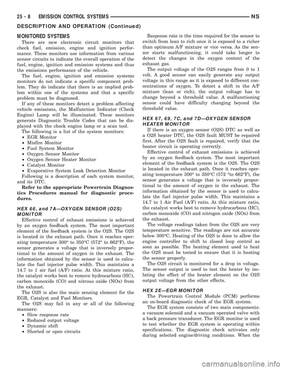
There are new electronic circuit monitors that
check fuel, emission, engine and ignition perfor-
mance. These monitors use information from various
sensor circuits to indicate the overall operation of the
fuel, engine, ignition and emission systems and thus
the emissions performance of the vehicle.
The fuel, engine, ignition and emission systems
monitors do not indicate a specific component prob-
lem. They do indicate that there is an implied prob-
lem within one of the systems and that a specific
problem must be diagnosed.
If any of these monitors detect a problem affecting
vehicle emissions, the Malfunction Indicator (Check
Engine) Lamp will be illuminated. These monitors
generate Diagnostic Trouble Codes that can be dis-
played with the check engine lamp or a scan tool.
The following is a list of the system monitors:
²EGR Monitor
²Misfire Monitor
²Fuel System Monitor
²Oxygen Sensor Monitor
²Oxygen Sensor Heater Monitor
²Catalyst Monitor
²Evaporative System Leak Detection Monitor
Following is a description of each system monitor,
and its DTC.
Refer to the appropriate Powertrain Diagnos-
tics Procedures manual for diagnostic proce-
dures.
HEX 66, and 7AÐOXYGEN SENSOR (O2S)
MONITOR
Effective control of exhaust emissions is achieved
by an oxygen feedback system. The most important
element of the feedback system is the O2S. The O2S
is located in the exhaust path. Once it reaches oper-
ating temperature 300É to 350ÉC (572É to 662ÉF), the
sensor generates a voltage that is inversely propor-
tional to the amount of oxygen in the exhaust. The
information obtained by the sensor is used to calcu-
late the fuel injector pulse width. This maintains a
14.7 to 1 air fuel (A/F) ratio. At this mixture ratio,
the catalyst works best to remove hydrocarbons (HC),
carbon monoxide (CO) and nitrous oxide (NOx) from
the exhaust.
The O2S is also the main sensing element for the
EGR, Catalyst and Fuel Monitors.
The O2S may fail in any or all of the following
manners:
²Slow response rate
²Reduced output voltage
²Dynamic shift
²Shorted or open circuitsResponse rate is the time required for the sensor to
switch from lean to rich once it is exposed to a richer
than optimum A/F mixture or vice versa. As the sen-
sor starts malfunctioning, it could take longer to
detect the changes in the oxygen content of the
exhaust gas.
The output voltage of the O2S ranges from 0 to 1
volt. A good sensor can easily generate any output
voltage in this range as it is exposed to different con-
centrations of oxygen. To detect a shift in the A/F
mixture (lean or rich), the output voltage has to
change beyond a threshold value. A malfunctioning
sensor could have difficulty changing beyond the
threshold value.
HEX 67, 69, 7C, and 7DÐOXYGEN SENSOR
HEATER MONITOR
If there is an oxygen sensor (O2S) DTC as well as
a O2S heater DTC, the O2S fault MUST be repaired
first. After the O2S fault is repaired, verify that the
heater circuit is operating correctly.
Effective control of exhaust emissions is achieved
by an oxygen feedback system. The most important
element of the feedback system is the O2S. The O2S
is located in the exhaust path. Once it reaches oper-
ating temperature 300É to 350ÉC (572 Éto 662ÉF), the
sensor generates a voltage that is inversely propor-
tional to the amount of oxygen in the exhaust. The
information obtained by the sensor is used to calcu-
late the fuel injector pulse width. This maintains a
14.7 to 1 Air Fuel (A/F) ratio. At this mixture ratio,
the catalyst works best to remove hydrocarbons (HC),
carbon monoxide (CO) and nitrogen oxide (NOx) from
the exhaust.
The voltage readings taken from the O2S are very
temperature sensitive. The readings are not accurate
below 300ÉC. Heating of the O2S is done to allow the
engine controller to shift to closed loop control as
soon as possible. The heating element used to heat
the O2S must be tested to ensure that it is heating
the sensor properly.
The O2S circuit is monitored for a drop in voltage.
The sensor output is used to test the heater by iso-
lating the effect of the heater element on the O2S
output voltage from the other effects.
HEX 2EÐEGR MONITOR
The Powertrain Control Module (PCM) performs
an on-board diagnostic check of the EGR system.
The EGR system consists of two main components:
a vacuum solenoid and a vacuum operated valve with
a back pressure transducer. The EGR monitor is used
to test whether the EGR system is operating within
specifications. The diagnostic check activates only
during selected engine/driving conditions. When the
25 - 8 EMISSION CONTROL SYSTEMSNS
DESCRIPTION AND OPERATION (Continued)
Page 1914 of 1938
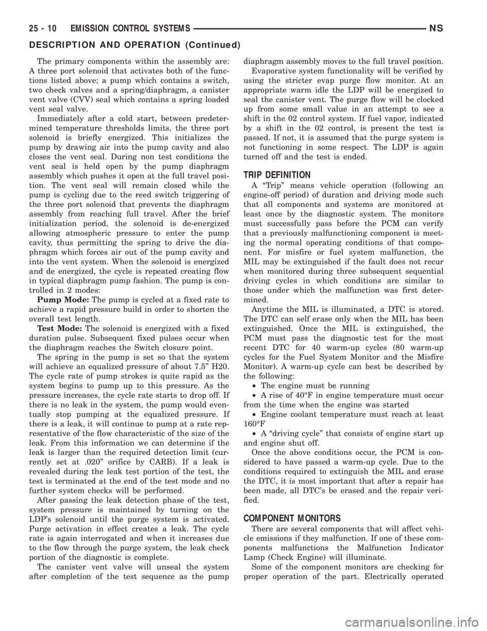
The primary components within the assembly are:
A three port solenoid that activates both of the func-
tions listed above; a pump which contains a switch,
two check valves and a spring/diaphragm, a canister
vent valve (CVV) seal which contains a spring loaded
vent seal valve.
Immediately after a cold start, between predeter-
mined temperature thresholds limits, the three port
solenoid is briefly energized. This initializes the
pump by drawing air into the pump cavity and also
closes the vent seal. During non test conditions the
vent seal is held open by the pump diaphragm
assembly which pushes it open at the full travel posi-
tion. The vent seal will remain closed while the
pump is cycling due to the reed switch triggering of
the three port solenoid that prevents the diaphragm
assembly from reaching full travel. After the brief
initialization period, the solenoid is de-energized
allowing atmospheric pressure to enter the pump
cavity, thus permitting the spring to drive the dia-
phragm which forces air out of the pump cavity and
into the vent system. When the solenoid is energized
and de energized, the cycle is repeated creating flow
in typical diaphragm pump fashion. The pump is con-
trolled in 2 modes:
Pump Mode:The pump is cycled at a fixed rate to
achieve a rapid pressure build in order to shorten the
overall test length.
Test Mode:The solenoid is energized with a fixed
duration pulse. Subsequent fixed pulses occur when
the diaphragm reaches the Switch closure point.
The spring in the pump is set so that the system
will achieve an equalized pressure of about 7.5º H20.
The cycle rate of pump strokes is quite rapid as the
system begins to pump up to this pressure. As the
pressure increases, the cycle rate starts to drop off. If
there is no leak in the system, the pump would even-
tually stop pumping at the equalized pressure. If
there is a leak, it will continue to pump at a rate rep-
resentative of the flow characteristic of the size of the
leak. From this information we can determine if the
leak is larger than the required detection limit (cur-
rently set at .020º orifice by CARB). If a leak is
revealed during the leak test portion of the test, the
test is terminated at the end of the test mode and no
further system checks will be performed.
After passing the leak detection phase of the test,
system pressure is maintained by turning on the
LDP's solenoid until the purge system is activated.
Purge activation in effect creates a leak. The cycle
rate is again interrogated and when it increases due
to the flow through the purge system, the leak check
portion of the diagnostic is complete.
The canister vent valve will unseal the system
after completion of the test sequence as the pumpdiaphragm assembly moves to the full travel position.
Evaporative system functionality will be verified by
using the stricter evap purge flow monitor. At an
appropriate warm idle the LDP will be energized to
seal the canister vent. The purge flow will be clocked
up from some small value in an attempt to see a
shift in the 02 control system. If fuel vapor, indicated
by a shift in the 02 control, is present the test is
passed. If not, it is assumed that the purge system is
not functioning in some respect. The LDP is again
turned off and the test is ended.
TRIP DEFINITION
A ªTripº means vehicle operation (following an
engine-off period) of duration and driving mode such
that all components and systems are monitored at
least once by the diagnostic system. The monitors
must successfully pass before the PCM can verify
that a previously malfunctioning component is meet-
ing the normal operating conditions of that compo-
nent. For misfire or fuel system malfunction, the
MIL may be extinguished if the fault does not recur
when monitored during three subsequent sequential
driving cycles in which conditions are similar to
those under which the malfunction was first deter-
mined.
Anytime the MIL is illuminated, a DTC is stored.
The DTC can self erase only when the MIL has been
extinguished. Once the MIL is extinguished, the
PCM must pass the diagnostic test for the most
recent DTC for 40 warm-up cycles (80 warm-up
cycles for the Fuel System Monitor and the Misfire
Monitor). A warm-up cycle can best be described by
the following:
²The engine must be running
²A rise of 40ÉF in engine temperature must occur
from the time when the engine was started
²Engine coolant temperature must reach at least
160ÉF
²A ªdriving cycleº that consists of engine start up
and engine shut off.
Once the above conditions occur, the PCM is con-
sidered to have passed a warm-up cycle. Due to the
conditions required to extinguish the MIL and erase
the DTC, it is most important that after a repair has
been made, all DTC's be erased and the repair veri-
fied.
COMPONENT MONITORS
There are several components that will affect vehi-
cle emissions if they malfunction. If one of these com-
ponents malfunctions the Malfunction Indicator
Lamp (Check Engine) will illuminate.
Some of the component monitors are checking for
proper operation of the part. Electrically operated
25 - 10 EMISSION CONTROL SYSTEMSNS
DESCRIPTION AND OPERATION (Continued)
Page 1932 of 1938

Generic Scan
Tool CodeDRB III Scan Tool Display
EEPROM Plausibility Ver Number Not Corresponding
P1685 Vehicle Theft Alarm Code Line Breakdown
P1690 Fan Control Open Circuit Fan #1
Fan Control Open Circuit Fan #2
Fan Control Short Circuit Fan #1
Fan Control Short Circuit Fan #2
P1695 A/C System Pressure Sensor Signal High Exceeded
A/C System Pressure Sensor Signal Low Exceeded
A/C System Pressure Supply Signal High Exceeded
A/C System Pressure Supply Signal Low Exceeded
P1703 Brake Signal Plaus With Redundant Contact
P1740 Clutch Signal Plausibilty
P1725 Inductive Aux. Speed Sensor Dynamic Plausibilty
Inductive Aux. Speed Sensor Overspeed Recognition
Inductive Aux Speed Sensor Plausibilty
Inductive Aux. Speed Sensor Static Plausibilty
25 - 4 EMISSION CONTROL SYSTEMNS/GS
DESCRIPTION AND OPERATION (Continued)