ESP CHRYSLER VOYAGER 1996 Workshop Manual
[x] Cancel search | Manufacturer: CHRYSLER, Model Year: 1996, Model line: VOYAGER, Model: CHRYSLER VOYAGER 1996Pages: 1938, PDF Size: 55.84 MB
Page 1210 of 1938
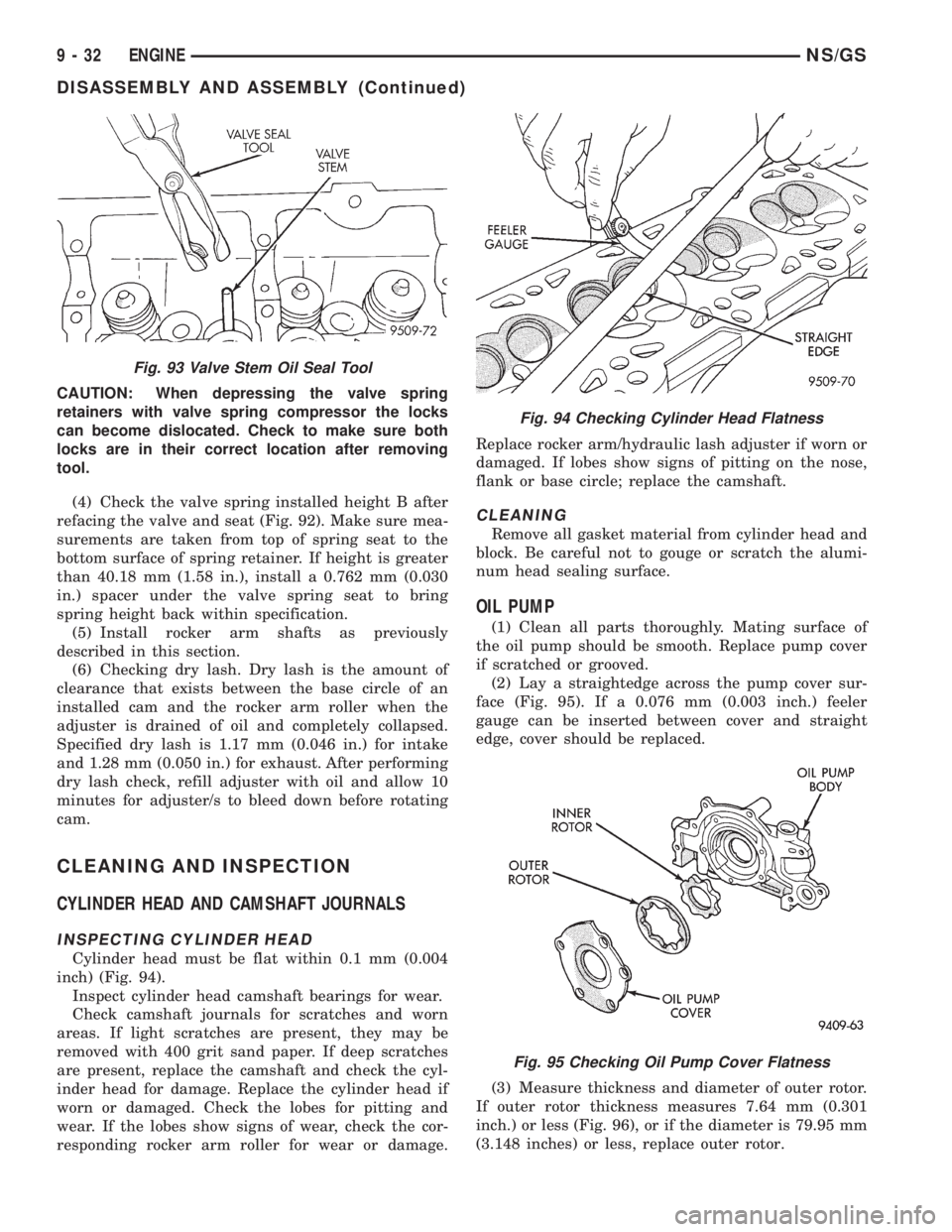
CAUTION: When depressing the valve spring
retainers with valve spring compressor the locks
can become dislocated. Check to make sure both
locks are in their correct location after removing
tool.
(4) Check the valve spring installed height B after
refacing the valve and seat (Fig. 92). Make sure mea-
surements are taken from top of spring seat to the
bottom surface of spring retainer. If height is greater
than 40.18 mm (1.58 in.), install a 0.762 mm (0.030
in.) spacer under the valve spring seat to bring
spring height back within specification.
(5) Install rocker arm shafts as previously
described in this section.
(6) Checking dry lash. Dry lash is the amount of
clearance that exists between the base circle of an
installed cam and the rocker arm roller when the
adjuster is drained of oil and completely collapsed.
Specified dry lash is 1.17 mm (0.046 in.) for intake
and 1.28 mm (0.050 in.) for exhaust. After performing
dry lash check, refill adjuster with oil and allow 10
minutes for adjuster/s to bleed down before rotating
cam.
CLEANING AND INSPECTION
CYLINDER HEAD AND CAMSHAFT JOURNALS
INSPECTING CYLINDER HEAD
Cylinder head must be flat within 0.1 mm (0.004
inch) (Fig. 94).
Inspect cylinder head camshaft bearings for wear.
Check camshaft journals for scratches and worn
areas. If light scratches are present, they may be
removed with 400 grit sand paper. If deep scratches
are present, replace the camshaft and check the cyl-
inder head for damage. Replace the cylinder head if
worn or damaged. Check the lobes for pitting and
wear. If the lobes show signs of wear, check the cor-
responding rocker arm roller for wear or damage.Replace rocker arm/hydraulic lash adjuster if worn or
damaged. If lobes show signs of pitting on the nose,
flank or base circle; replace the camshaft.
CLEANING
Remove all gasket material from cylinder head and
block. Be careful not to gouge or scratch the alumi-
num head sealing surface.
OIL PUMP
(1) Clean all parts thoroughly. Mating surface of
the oil pump should be smooth. Replace pump cover
if scratched or grooved.
(2) Lay a straightedge across the pump cover sur-
face (Fig. 95). If a 0.076 mm (0.003 inch.) feeler
gauge can be inserted between cover and straight
edge, cover should be replaced.
(3) Measure thickness and diameter of outer rotor.
If outer rotor thickness measures 7.64 mm (0.301
inch.) or less (Fig. 96), or if the diameter is 79.95 mm
(3.148 inches) or less, replace outer rotor.
Fig. 93 Valve Stem Oil Seal Tool
Fig. 94 Checking Cylinder Head Flatness
Fig. 95 Checking Oil Pump Cover Flatness
9 - 32 ENGINENS/GS
DISASSEMBLY AND ASSEMBLY (Continued)
Page 1225 of 1938
HYDRAULIC TAPPETS
Before disassembling any part of the engine to cor-
rect tappet noise, check the oil pressure. If vehicle
has no oil pressure gauge, install a reliable gauge at
the pressure sending unit. The pressure should be
between 3.5 bars to 5.0 bars at 4000 RPM.
Check the oil level after the engine reaches normal
operating temperature. Allow 5 minutes to stabilize
oil level, check dipstick. The oil level in the pan
should never be above the FULL mark or below the
ADD OIL mark on dipstick. Either of these 2 condi-
tions could be responsible for noisy tappets.
OIL LEVEL HIGH
If oil level is above the FULL mark, it is possible
for the connecting rods to dip into the oil. With the
engine running, this condition could create foam in
the oil pan. Foam in oil pan would be fed to the
hydraulic tappets by the oil pump causing them to
lose length and allow valves to seat noisily.
OIL LEVEL LOW
Low oil level may allow oil pump to take in air.
When air is fed to the tappets, they lose length which
allows valves to seat noisily. Any leaks on intake side
of oil pump through which air can be drawn will cre-
ate the same tappet action. Check the lubrication
system from the intake strainer to the pump cover,
including the relief valve retainer cap. When tappet
noise is due to aeration, it may be intermittent or
constant, and usually more than 1 tappet will be
noisy. When oil level and leaks have been corrected,
operate the engine at fast idle. Run engine for a suf-
ficient time to allow all of the air inside the tappets
to be bled out.
TAPPET NOISE DIAGNOSIS
(1) To determine source of tappet noise, operate
engine at idle with cylinder head covers removed.
(2) Feel each valve spring or rocker arm to detect
noisy tappet. The noisy tappet will cause the affected
spring and/or rocker arm to vibrate or feel rough in
operation.
NOTE: Worn valve guides or cocked springs are
sometimes mistaken for noisy tappets. If such is
the case, noise may be dampened by applying side
thrust on the valve spring. If noise is not apprecia-
bly reduced, it can be assumed the noise is in the
tappet. Inspect the rocker arm push rod sockets
and push rod ends for wear.
(3) Valve tappet noise ranges from light noise to a
heavy click. A light noise is usually caused by exces-
sive leak down around the unit plunger or by the
plunger partially sticking in the tappet body cylinder.
The tappet should be replaced. A heavy click iscaused by a tappet check valve not seating or by for-
eign particles becoming wedged between the plunger
and the tappet body. This will cause the plunger to
stick in the down position. This heavy click will be
accompanied by excessive clearance between the
valve stem and rocker arm as valve closes. In either
case, tappet assembly should be removed for inspec-
tion and cleaning.
(4) The valve train generates a noise very much
like a light tappet noise during normal operation.
Care must be taken to ensure that tappets are mak-
ing the noise. In general, if more than one tappet
seems to be noisy, its probably not the tappets.
SERVICE PROCEDURES
CHECKING OIL LEVEL
To assure proper engine lubrication, the engine oil
must be maintained at the correct level. Check the
oil level at regular intervals, such as every fuel stop.
The best time to check the oil level is about 5 min-
utes after a fully warmed-up engine is shut off, or
before starting the vehicle after it has sat overnight.
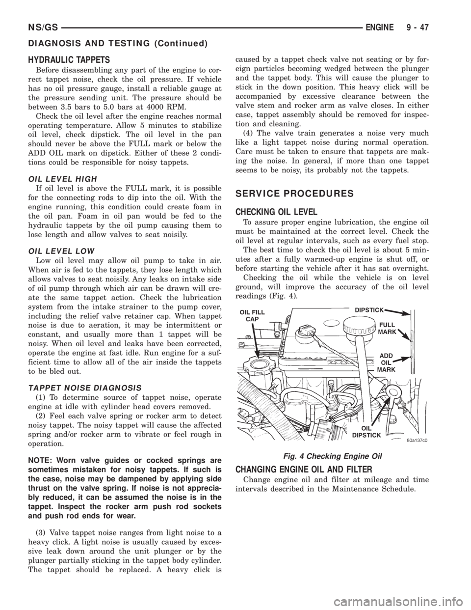
Checking the oil while the vehicle is on level
ground, will improve the accuracy of the oil level
readings (Fig. 4).
CHANGING ENGINE OIL AND FILTER
Change engine oil and filter at mileage and time
intervals described in the Maintenance Schedule.
Fig. 4 Checking Engine Oil
NS/GSENGINE 9 - 47
DIAGNOSIS AND TESTING (Continued)
Page 1228 of 1938
VALVE STAND DOWN
Valve stand down is to maintain the adequate com-
pression ratio.
(1) Invert cylinder head.
(2) Fit each valve to its respective valve guide.
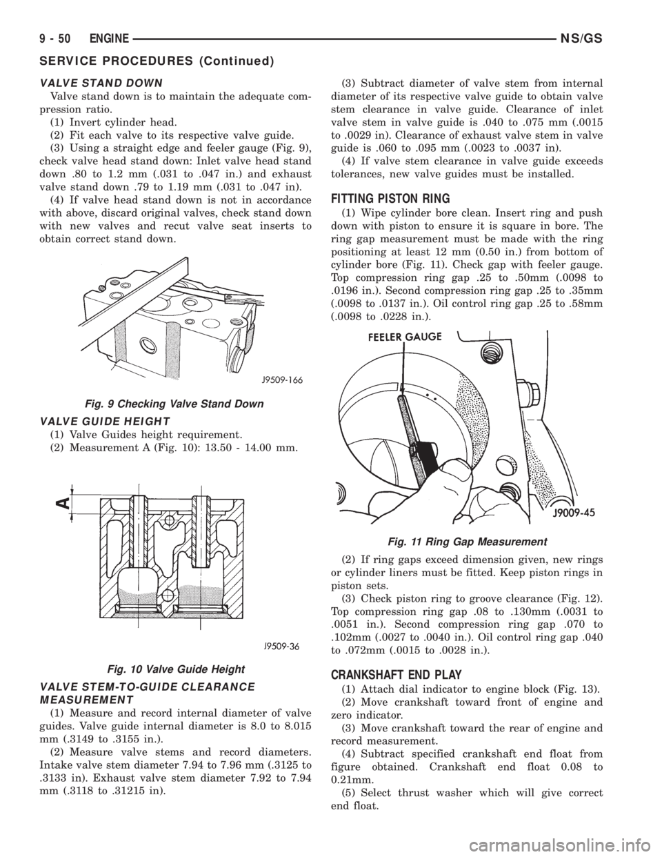
(3) Using a straight edge and feeler gauge (Fig. 9),
check valve head stand down: Inlet valve head stand
down .80 to 1.2 mm (.031 to .047 in.) and exhaust
valve stand down .79 to 1.19 mm (.031 to .047 in).
(4) If valve head stand down is not in accordance
with above, discard original valves, check stand down
with new valves and recut valve seat inserts to
obtain correct stand down.
VALVE GUIDE HEIGHT
(1) Valve Guides height requirement.
(2) Measurement A (Fig. 10): 13.50 - 14.00 mm.
VALVE STEM-TO-GUIDE CLEARANCE
MEASUREMENT
(1) Measure and record internal diameter of valve
guides. Valve guide internal diameter is 8.0 to 8.015
mm (.3149 to .3155 in.).
(2) Measure valve stems and record diameters.
Intake valve stem diameter 7.94 to 7.96 mm (.3125 to
.3133 in). Exhaust valve stem diameter 7.92 to 7.94
mm (.3118 to .31215 in).(3) Subtract diameter of valve stem from internal
diameter of its respective valve guide to obtain valve
stem clearance in valve guide. Clearance of inlet
valve stem in valve guide is .040 to .075 mm (.0015
to .0029 in). Clearance of exhaust valve stem in valve
guide is .060 to .095 mm (.0023 to .0037 in).
(4) If valve stem clearance in valve guide exceeds
tolerances, new valve guides must be installed.
FITTING PISTON RING
(1) Wipe cylinder bore clean. Insert ring and push
down with piston to ensure it is square in bore. The
ring gap measurement must be made with the ring
positioning at least 12 mm (0.50 in.) from bottom of
cylinder bore (Fig. 11). Check gap with feeler gauge.
Top compression ring gap .25 to .50mm (.0098 to
.0196 in.). Second compression ring gap .25 to .35mm
(.0098 to .0137 in.). Oil control ring gap .25 to .58mm
(.0098 to .0228 in.).
(2) If ring gaps exceed dimension given, new rings
or cylinder liners must be fitted. Keep piston rings in
piston sets.
(3) Check piston ring to groove clearance (Fig. 12).
Top compression ring gap .08 to .130mm (.0031 to
.0051 in.). Second compression ring gap .070 to
.102mm (.0027 to .0040 in.). Oil control ring gap .040
to .072mm (.0015 to .0028 in.).
CRANKSHAFT END PLAY
(1) Attach dial indicator to engine block (Fig. 13).
(2) Move crankshaft toward front of engine and
zero indicator.
(3) Move crankshaft toward the rear of engine and
record measurement.
(4) Subtract specified crankshaft end float from
figure obtained. Crankshaft end float 0.08 to
0.21mm.
(5) Select thrust washer which will give correct
end float.
Fig. 9 Checking Valve Stand Down
Fig. 10 Valve Guide Height
Fig. 11 Ring Gap Measurement
9 - 50 ENGINENS/GS
SERVICE PROCEDURES (Continued)
Page 1233 of 1938
(3) Install cylinder head cover, torque nuts to 14.7
N´m (132 in. lbs.).
(4) Install coolant pressure tank.
(5) Install breather hose.
(6) Install generator bracket, tighten bolts to 7
N´m (4 ft. lbs.).
(7) Connect the service valves to the A/C compres-
sor ports, if equipped with air conditioning.
(8) Connect battery cable.
VALVE SPRINGSÐCYLINDER HEAD NOT
REMOVED
This procedure can be done with the engine cylin-
der head installed on the block.
REMOVAL
Each valve spring is held in place by a retainer
and a set of conical valve locks. The locks can be
removed only by compressing the valve spring.
(1) Remove the engine cylinder head cover, refer to
cylinder head cover removal in this section.
(2) Remove rocker arms assemblies for access to
each valve spring to be removed.
(3) Remove push rods. Retain the push rods, and
rocker arms assemblies in the same order and posi-
tion as removed.
(4) Inspect the springs and retainer for cracks and
possible signs of weakening.
(5) Install an air hose adaptor in the fuel injector
hole.
(6) Connect an air hose to the adapter and apply
air pressure slowly. Maintain at least 621 kPa (90psi) of air pressure in the cylinder to hold the valves
against their seats.
(7) Tap the retainer or tip with a rawhide hammer
to loosen the lock from the retainer. Use Valve Spring
Compressor Tool to compress the spring and remove
the locks.
(8) Remove valve spring and retainer.
Inspect the valve stems, especially the grooves. An
Arkansas smooth stone should be used to remove
nicks and high spots.
INSTALLATION
(1) Install valve spring and retainer.
(2) Compress the valve spring with Valve Spring
Compressor Tool and insert the valve locks. Release
the spring tension and remove the tool. Tap the
spring from side-to-side to ensure that the spring is
seated properly on the engine cylinder head.
(3) Disconnect the air hose. Remove the adaptor
from the fuel injector hole and install the fuel injec-
tor.
(4) Repeat the procedures for each remaining valve
spring to be removed.
(5) Install the push rods. Ensure the bottom end of
each rod is centered in the plunger cap seat of the
hydraulic valve tappet.
(6) Install the rocker arm assemblies, at their orig-
inal location.
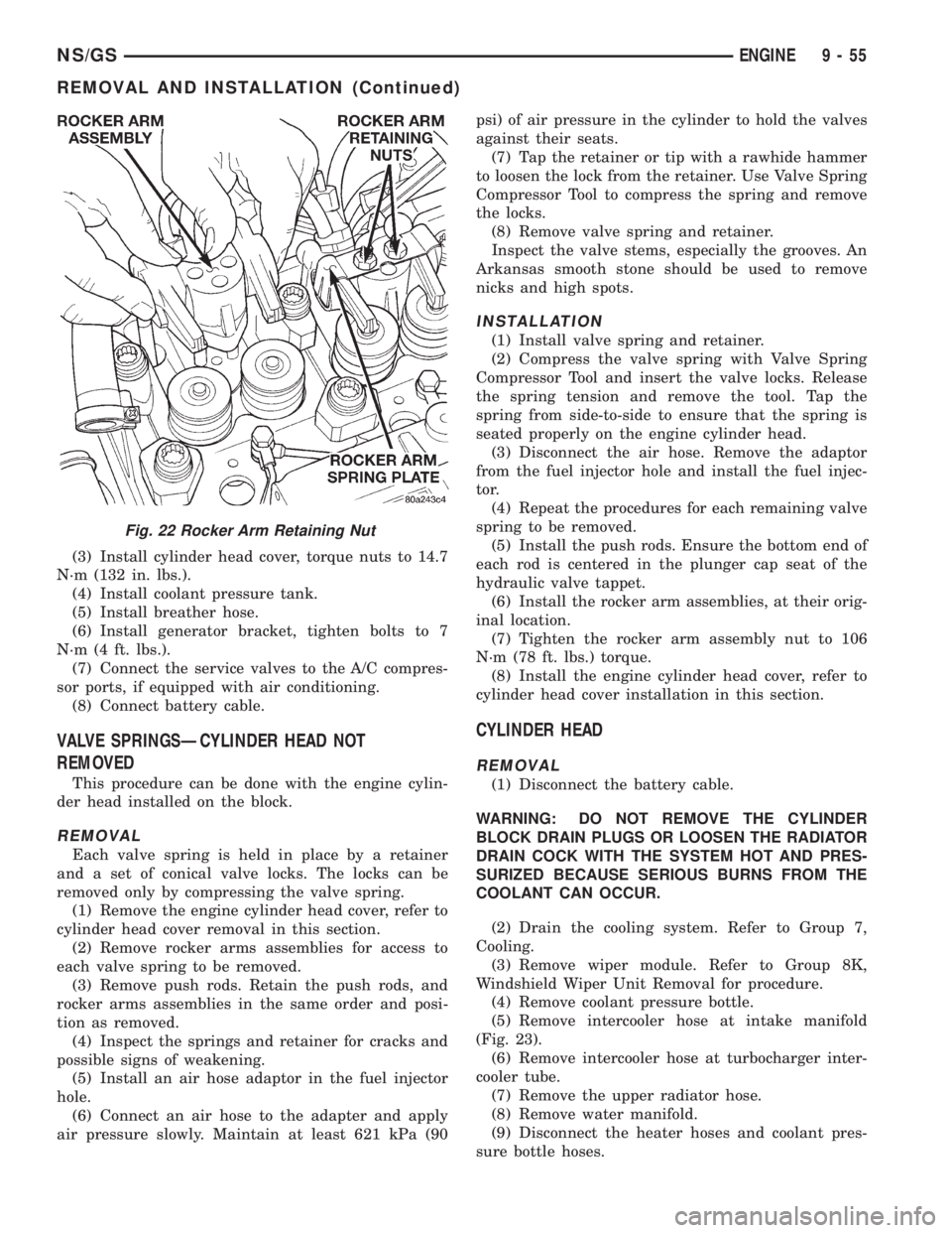
(7) Tighten the rocker arm assembly nut to 106
N´m (78 ft. lbs.) torque.
(8) Install the engine cylinder head cover, refer to
cylinder head cover installation in this section.
CYLINDER HEAD
REMOVAL
(1) Disconnect the battery cable.
WARNING: DO NOT REMOVE THE CYLINDER
BLOCK DRAIN PLUGS OR LOOSEN THE RADIATOR
DRAIN COCK WITH THE SYSTEM HOT AND PRES-
SURIZED BECAUSE SERIOUS BURNS FROM THE
COOLANT CAN OCCUR.
(2) Drain the cooling system. Refer to Group 7,
Cooling.
(3) Remove wiper module. Refer to Group 8K,
Windshield Wiper Unit Removal for procedure.
(4) Remove coolant pressure bottle.
(5) Remove intercooler hose at intake manifold
(Fig. 23).
(6) Remove intercooler hose at turbocharger inter-
cooler tube.
(7) Remove the upper radiator hose.
(8) Remove water manifold.
(9) Disconnect the heater hoses and coolant pres-
sure bottle hoses.
Fig. 22 Rocker Arm Retaining Nut
NS/GSENGINE 9 - 55
REMOVAL AND INSTALLATION (Continued)
Page 1238 of 1938
(36) Operate the engine with the radiator cap off.
Inspect for leaks and continue operating the engine
until the thermostat opens. Add coolant, if required.
VALVES AND VALVE SPRINGSÐHEAD OFF
This procedure is done with the engine cylinder
head removed from the block.
REMOVAL
(1) Remove the engine cylinder head from the cyl-
inder block. Refer to cylinder head removal in this
section.
(2) Use Valve Spring Compressor Tool and com-
press each valve spring.
(3) Remove the valve locks, retainers, and springs.
(4) Use an Arkansas smooth stone or a jewelers
file to remove any burrs on the top of the valve stem,
especially around the groove for the locks.
(5) Remove the valves, and place them in a rack in
the same order as removed.
INSTALLATION
(1) Fit each valve to its respective valve guide.
NOTE: If valves and valve seats have been refaced
refer to Service Procedures in this section. Follow
The Valve Stand Down procedure.
(2) Install lower, washer and spring.
(3) Install upper spring collar, and compress valve
spring with spring compressor tool. Install split cone
retainers.
HYDRAULIC TAPPETS
REMOVAL
(1) Remove coolant pressure bottle.
(2) Remove cylinder head cover. Refer to cylinder
head cover removal in this section.
(3) Remove rocker assembly and push rods. Iden-
tify push rods to ensure installation in original loca-
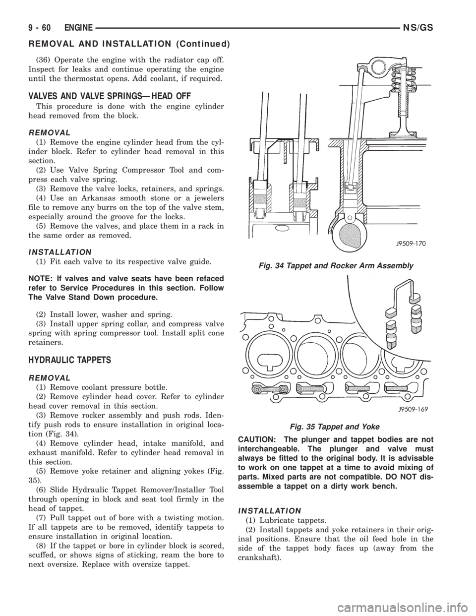
tion (Fig. 34).
(4) Remove cylinder head, intake manifold, and
exhaust manifold. Refer to cylinder head removal in
this section.
(5) Remove yoke retainer and aligning yokes (Fig.
35).
(6) Slide Hydraulic Tappet Remover/Installer Tool
through opening in block and seat tool firmly in the
head of tappet.
(7) Pull tappet out of bore with a twisting motion.
If all tappets are to be removed, identify tappets to
ensure installation in original location.
(8) If the tappet or bore in cylinder block is scored,
scuffed, or shows signs of sticking, ream the bore to
next oversize. Replace with oversize tappet.CAUTION: The plunger and tappet bodies are not
interchangeable. The plunger and valve must
always be fitted to the original body. It is advisable
to work on one tappet at a time to avoid mixing of
parts. Mixed parts are not compatible. DO NOT dis-
assemble a tappet on a dirty work bench.
INSTALLATION
(1) Lubricate tappets.
(2) Install tappets and yoke retainers in their orig-
inal positions. Ensure that the oil feed hole in the
side of the tappet body faces up (away from the
crankshaft).
Fig. 34 Tappet and Rocker Arm Assembly
Fig. 35 Tappet and Yoke
9 - 60 ENGINENS/GS
REMOVAL AND INSTALLATION (Continued)
Page 1252 of 1938
retainer and plunger spring. Check valve could be
flat or ball.
Assemble tappets in reverse order.
CLEANING AND INSPECTION
CYLINDER HEAD COVERS
Remove any original sealer from the cover sealing
surface of the engine cylinder head.
Remove all residue from the sealing surface using
a clean, dry cloth.
ROCKER ARMS AND PUSH RODS
CLEANING
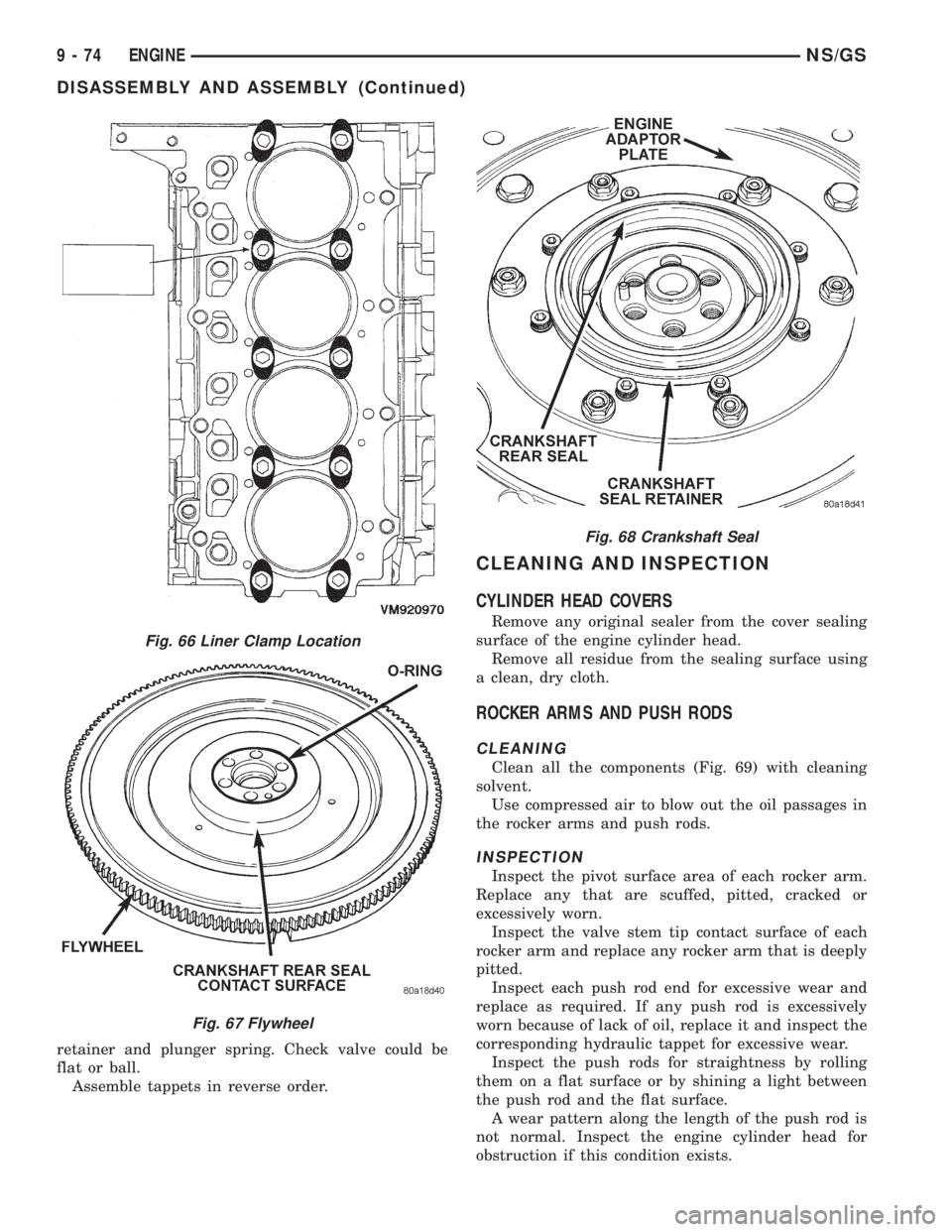
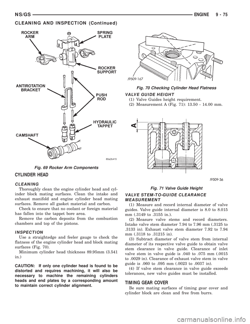
Clean all the components (Fig. 69) with cleaning
solvent.
Use compressed air to blow out the oil passages in
the rocker arms and push rods.
INSPECTION
Inspect the pivot surface area of each rocker arm.
Replace any that are scuffed, pitted, cracked or
excessively worn.
Inspect the valve stem tip contact surface of each
rocker arm and replace any rocker arm that is deeply
pitted.
Inspect each push rod end for excessive wear and
replace as required. If any push rod is excessively
worn because of lack of oil, replace it and inspect the
corresponding hydraulic tappet for excessive wear.
Inspect the push rods for straightness by rolling
them on a flat surface or by shining a light between
the push rod and the flat surface.
A wear pattern along the length of the push rod is
not normal. Inspect the engine cylinder head for
obstruction if this condition exists.
Fig. 66 Liner Clamp Location
Fig. 67 Flywheel
Fig. 68 Crankshaft Seal
9 - 74 ENGINENS/GS
DISASSEMBLY AND ASSEMBLY (Continued)
Page 1253 of 1938
CYLINDER HEAD
CLEANING
Thoroughly clean the engine cylinder head and cyl-
inder block mating surfaces. Clean the intake and
exhaust manifold and engine cylinder head mating
surfaces. Remove all gasket material and carbon.
Check to ensure that no coolant or foreign material
has fallen into the tappet bore area.
Remove the carbon deposits from the combustion
chambers and top of the pistons.
INSPECTION
Use a straightedge and feeler gauge to check the
flatness of the engine cylinder head and block mating
surfaces (Fig. 70).
Minimum cylinder head thickness 89.95mm (3.541
in.)
CAUTION: If only one cylinder head is found to be
distorted and requires machining, it will also be
necessary to machine the remaining cylinders
heads and end plates by a corresponding amount
to maintain correct cylinder alignment.
VALVE GUIDE HEIGHT
(1) Valve Guides height requirement.
(2) Measurement A (Fig. 71): 13.50 - 14.00 mm.
VALVE STEM-TO-GUIDE CLEARANCE
MEASUREMENT
(1) Measure and record internal diameter of valve
guides. Valve guide internal diameter is 8.0 to 8.015
mm (.3149 to .3155 in.).
(2) Measure valve stems and record diameters.
Intake valve stem diameter 7.94 to 7.96 mm (.3125 to
.3133 in). Exhaust valve stem diameter 7.92 to 7.94
mm (.3118 to .31215 in).
(3) Subtract diameter of valve stem from internal
diameter of its respective valve guide to obtain valve
stem clearance in valve guide. Clearance of inlet
valve stem in valve guide is .040 to .075 mm (.0015
to .0029 in). Clearance of exhaust valve stem in valve
guide is .060 to .095 mm (.0023 to .0037 in).
(4) If valve stem clearance in valve guide exceeds
tolerances, new valve guides must be installed.
TIMING GEAR COVER
Be sure mating surfaces of timing gear cover and
cylinder block are clean and free from burrs.
Fig. 69 Rocker Arm Components
Fig. 70 Checking Cylinder Head Flatness
Fig. 71 Valve Guide Height
NS/GSENGINE 9 - 75
CLEANING AND INSPECTION (Continued)
Page 1255 of 1938
(3.6196-3.6200 in.). Maximum wear limit .05mm
(.0019 in.).
(2) Check piston pin bores in piston for roundness.
Make 3 checks at 120É intervals. Maximum out of
roundness .05mm (.0019in.).
(3) The piston diameter should be measured
approximately 15 mm (.590 in.) up from the base.
(4) Skirt wear should not exceed 0.1 mm (.00039
in.).
(5) The clearance between the cylinder liner and
piston should not exceed 0.25 mm (.0009 in.).
(6) Make sure the weight of the pistons does not
differ by more than 5 g.
CONNECTING ROD
(1) Assemble bearing shells and bearing caps to
their respective connecting rods ensuring that the
serrations on the cap and reference marks are
aligned.
(2) Tighten bearing cap bolts to 29 N´m (21 ft. lbs.)
plus 60É.
(3) Check and record internal diameter of crank
end of connecting rod.
Note: When changing connecting rods, all four
must have the same weight and be stamped with the
same number.Replacement connecting rods will
only be supplied in sets of four.
(4) Connecting rods are supplied in sets of four
since they all must be of the same weight category.
Max allowable weight difference is 18 gr.NOTE:On
one side of the big end of the con-rod there is a two-
digit number which refers to the weight category. On
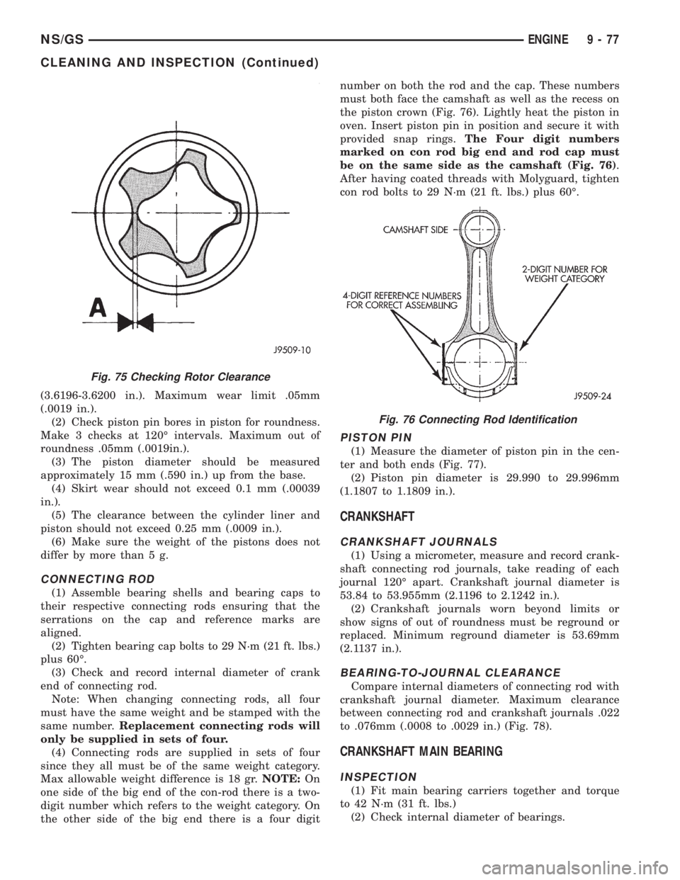
the other side of the big end there is a four digitnumber on both the rod and the cap. These numbers
must both face the camshaft as well as the recess on
the piston crown (Fig. 76). Lightly heat the piston in
oven. Insert piston pin in position and secure it with
provided snap rings.The Four digit numbers
marked on con rod big end and rod cap must
be on the same side as the camshaft (Fig. 76).
After having coated threads with Molyguard, tighten
con rod bolts to 29 N´m (21 ft. lbs.) plus 60É.
PISTON PIN
(1) Measure the diameter of piston pin in the cen-
ter and both ends (Fig. 77).
(2) Piston pin diameter is 29.990 to 29.996mm
(1.1807 to 1.1809 in.).
CRANKSHAFT
CRANKSHAFT JOURNALS
(1) Using a micrometer, measure and record crank-
shaft connecting rod journals, take reading of each
journal 120É apart. Crankshaft journal diameter is
53.84 to 53.955mm (2.1196 to 2.1242 in.).
(2) Crankshaft journals worn beyond limits or
show signs of out of roundness must be reground or
replaced. Minimum reground diameter is 53.69mm
(2.1137 in.).
BEARING-TO-JOURNAL CLEARANCE
Compare internal diameters of connecting rod with
crankshaft journal diameter. Maximum clearance
between connecting rod and crankshaft journals .022
to .076mm (.0008 to .0029 in.) (Fig. 78).
CRANKSHAFT MAIN BEARING
INSPECTION
(1) Fit main bearing carriers together and torque
to 42 N´m (31 ft. lbs.)
(2) Check internal diameter of bearings.
Fig. 75 Checking Rotor Clearance
Fig. 76 Connecting Rod Identification
NS/GSENGINE 9 - 77
CLEANING AND INSPECTION (Continued)
Page 1265 of 1938
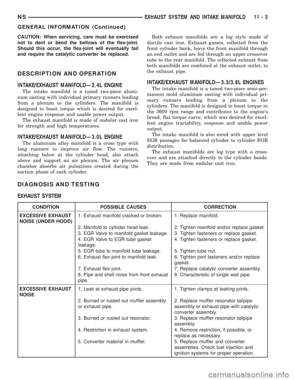
CAUTION: When servicing, care must be exercised
not to dent or bend the bellows of the flex-joint.
Should this occur, the flex-joint will eventually fail
and require the catalytic converter be replaced.
DESCRIPTION AND OPERATION
INTAKE/EXHAUST MANIFOLDÐ2.4L ENGINE
The intake manifold is a tuned two-piece alumi-
num casting with individual primary runners leading
from a plenum to the cylinders. The manifold is
designed to boost torque which is desired for excel-
lent engine response and usable power output.
The exhaust manifold is made of nodular cast iron
for strength and high temperatures.
INTAKE/EXHAUST MANIFOLDÐ3.0L ENGINE
The aluminum alloy manifold is a cross type with
long runners to improve air flow. The runners,
attaching below at the cylinder head, also attach
above and support an air plenum. The air plenum
chamber absorbs air pulsations created during the
suction phase of each cylinder.Both exhaust manifolds are a log style made of
ductile cast iron. Exhaust gasses, collected from the
front cylinder bank, leave the front manifold through
an end outlet and are fed through an upper crossover
tube to the rear manifold. The collected exhaust from
both manifolds are combined at the exhaust outlet, to
the exhaust pipe.
INTAKE/EXHAUST MANIFOLDÐ3.3/3.8L ENGINES
The intake manifold is a tuned two-piece semi-per-
manent mold aluminum casting with individual pri-
mary runners leading from a plenum to the
cylinders. The manifold is designed to boost torque in
the 3600 rpm range and contributes to the engine's
broad, flat torque curve, which was desired for excel-
lent engine tractability, response and usable power
output.
The intake manifold is also cored with upper level
EGR passages for balanced cylinder to cylinder EGR
distribution.
The exhaust manifolds are log type with a cross-
over and are attached directly to the cylinder heads.
They are made from nodular cast iron.
DIAGNOSIS AND TESTING
EXHAUST SYSTEM
CONDITION POSSIBLE CAUSES CORRECTION
EXCESSIVE EXHAUST
NOISE (UNDER HOOD)1. Exhaust manifold cracked or broken. 1. Replace manifold.
2. Manifold to cylinder head leak. 2. Tighten manifold and/or replace gasket.
3. EGR Valve to manifold gasket leakage. 3. Tighten fasteners or replace gasket.
4. EGR Valve to EGR tube gasket
leakage.4. Tighten fasteners or replace gasket.
5. EGR tube to manifold tube leakage. 5. Tighten tube nut.
6. Exhaust flex-joint to manifold leak. 6. Tighten joint fasteners and/or replace
gasket.
7. Exhaust flex-joint. 7. Replace catalytic converter assembly.
8. Pipe and shell noise from front exhaust
pipe.8. Characteristic of single wall pipe.
EXCESSIVE EXHAUST
NOISE1. Leak at exhaust pipe joints. 1. Tighten clamps at leaking joints.
2. Burned or rusted out muffler assembly
or exhaust pipe.2. Replace muffler resonator tailpipe
assembly or exhaust pipe with catalytic
converter assembly.
3. Burned or rusted out resonator. 3. Replace muffler resonator tailpipe
assembly.
4. Restriction in exhaust system. 4. Remove restriction, if possible, or
replace as necessary.
5. Converter material in muffler. 5. Replace muffler and converter
assemblies. Check fuel injection and
ignition systems for proper operation.
NSEXHAUST SYSTEM AND INTAKE MANIFOLD 11 - 3
GENERAL INFORMATION (Continued)
Page 1296 of 1938
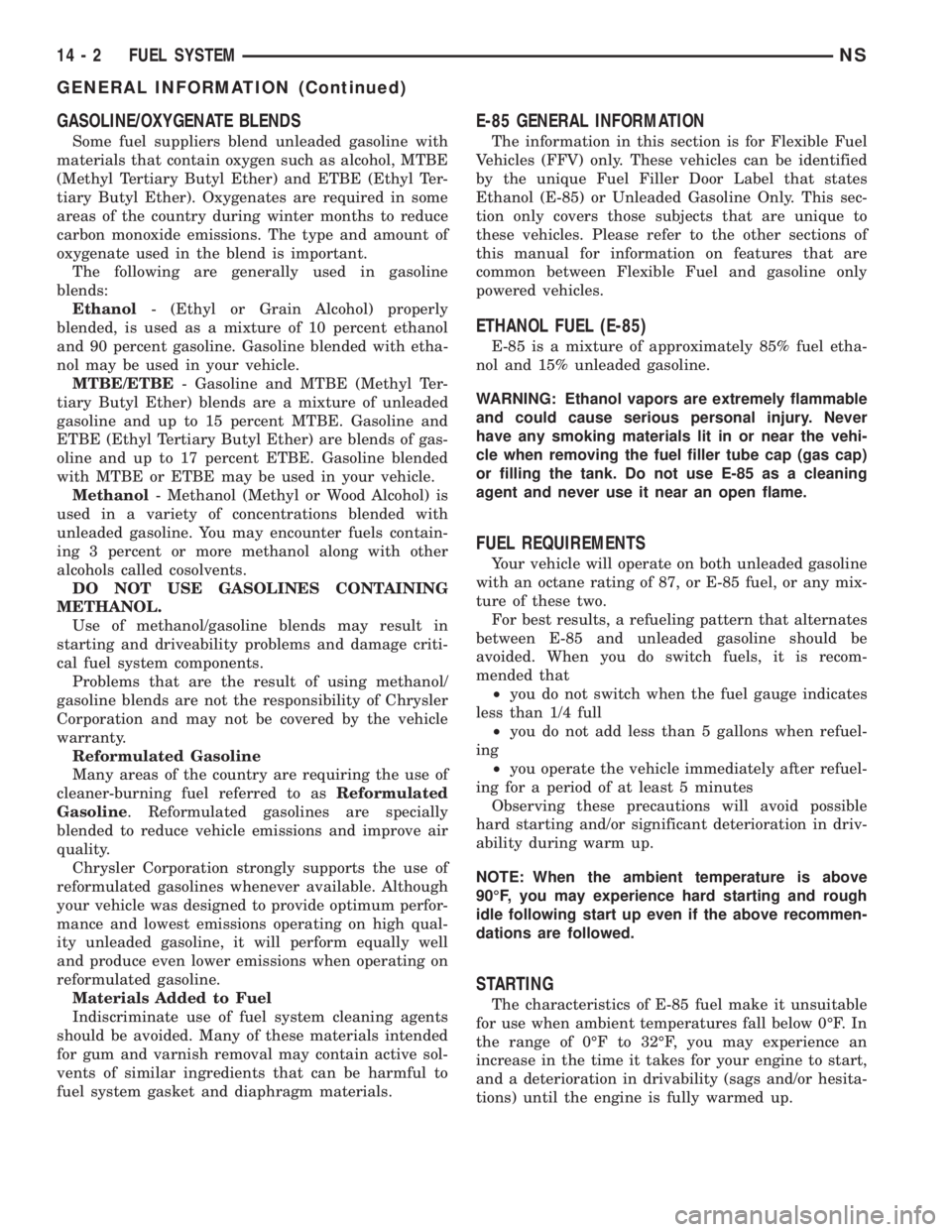
GASOLINE/OXYGENATE BLENDS
Some fuel suppliers blend unleaded gasoline with
materials that contain oxygen such as alcohol, MTBE
(Methyl Tertiary Butyl Ether) and ETBE (Ethyl Ter-
tiary Butyl Ether). Oxygenates are required in some
areas of the country during winter months to reduce
carbon monoxide emissions. The type and amount of
oxygenate used in the blend is important.
The following are generally used in gasoline
blends:
Ethanol- (Ethyl or Grain Alcohol) properly
blended, is used as a mixture of 10 percent ethanol
and 90 percent gasoline. Gasoline blended with etha-
nol may be used in your vehicle.
MTBE/ETBE- Gasoline and MTBE (Methyl Ter-
tiary Butyl Ether) blends are a mixture of unleaded
gasoline and up to 15 percent MTBE. Gasoline and
ETBE (Ethyl Tertiary Butyl Ether) are blends of gas-
oline and up to 17 percent ETBE. Gasoline blended
with MTBE or ETBE may be used in your vehicle.
Methanol- Methanol (Methyl or Wood Alcohol) is
used in a variety of concentrations blended with
unleaded gasoline. You may encounter fuels contain-
ing 3 percent or more methanol along with other
alcohols called cosolvents.
DO NOT USE GASOLINES CONTAINING
METHANOL.
Use of methanol/gasoline blends may result in
starting and driveability problems and damage criti-
cal fuel system components.
Problems that are the result of using methanol/
gasoline blends are not the responsibility of Chrysler
Corporation and may not be covered by the vehicle
warranty.
Reformulated Gasoline
Many areas of the country are requiring the use of
cleaner-burning fuel referred to asReformulated
Gasoline. Reformulated gasolines are specially
blended to reduce vehicle emissions and improve air
quality.
Chrysler Corporation strongly supports the use of
reformulated gasolines whenever available. Although
your vehicle was designed to provide optimum perfor-
mance and lowest emissions operating on high qual-
ity unleaded gasoline, it will perform equally well
and produce even lower emissions when operating on
reformulated gasoline.
Materials Added to Fuel
Indiscriminate use of fuel system cleaning agents
should be avoided. Many of these materials intended
for gum and varnish removal may contain active sol-
vents of similar ingredients that can be harmful to
fuel system gasket and diaphragm materials.
E-85 GENERAL INFORMATION
The information in this section is for Flexible Fuel
Vehicles (FFV) only. These vehicles can be identified
by the unique Fuel Filler Door Label that states
Ethanol (E-85) or Unleaded Gasoline Only. This sec-
tion only covers those subjects that are unique to
these vehicles. Please refer to the other sections of
this manual for information on features that are
common between Flexible Fuel and gasoline only
powered vehicles.
ETHANOL FUEL (E-85)
E-85 is a mixture of approximately 85% fuel etha-
nol and 15% unleaded gasoline.
WARNING: Ethanol vapors are extremely flammable
and could cause serious personal injury. Never
have any smoking materials lit in or near the vehi-
cle when removing the fuel filler tube cap (gas cap)
or filling the tank. Do not use E-85 as a cleaning
agent and never use it near an open flame.
FUEL REQUIREMENTS
Your vehicle will operate on both unleaded gasoline
with an octane rating of 87, or E-85 fuel, or any mix-
ture of these two.
For best results, a refueling pattern that alternates
between E-85 and unleaded gasoline should be
avoided. When you do switch fuels, it is recom-
mended that
²you do not switch when the fuel gauge indicates
less than 1/4 full
²you do not add less than 5 gallons when refuel-
ing
²you operate the vehicle immediately after refuel-
ing for a period of at least 5 minutes
Observing these precautions will avoid possible
hard starting and/or significant deterioration in driv-
ability during warm up.
NOTE: When the ambient temperature is above
90ÉF, you may experience hard starting and rough
idle following start up even if the above recommen-
dations are followed.
STARTING
The characteristics of E-85 fuel make it unsuitable
for use when ambient temperatures fall below 0ÉF. In
the range of 0ÉF to 32ÉF, you may experience an
increase in the time it takes for your engine to start,
and a deterioration in drivability (sags and/or hesita-
tions) until the engine is fully warmed up.
14 - 2 FUEL SYSTEMNS
GENERAL INFORMATION (Continued)