ESP inoperative CHRYSLER VOYAGER 1996 Service Manual
[x] Cancel search | Manufacturer: CHRYSLER, Model Year: 1996, Model line: VOYAGER, Model: CHRYSLER VOYAGER 1996Pages: 1938, PDF Size: 55.84 MB
Page 339 of 1938

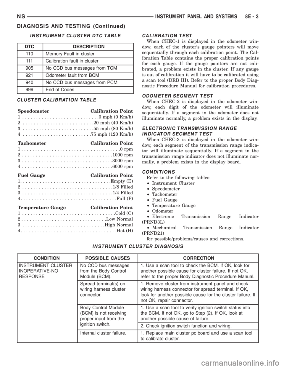
CLUSTER CALIBRATION TABLE
Speedometer Calibration Point
1 ............................0mph(0Km/h)
2 ..........................20mph(40Km/h)
3 ..........................55mph(80Km/h)
4 .........................75mph(120 Km/h)
Tachometer Calibration Point
1....................................0rpm
2 .................................1000 rpm
3 .................................3000 rpm
4 .................................6000 rpm
Fuel Gauge Calibration Point
1.................................Empty (E)
2 .................................1/8 Filled
3 .................................1/4 Filled
4...................................Full (F)
Temperature Gauge Calibration Point
1 ..................................Cold (C)
2...............................Low Normal
3 ..............................High Normal
4...................................Hot (H)
CALIBRATION TEST
When CHEC-1 is displayed in the odometer win-
dow, each of the cluster's gauge pointers will move
sequentially through each calibration point. The Cal-
ibration Table contains the proper calibration points
for each gauge. If the gauge pointers are not cali-
brated, a problem exists in the cluster. If any gauge
is out of calibration it will have to be calibrated using
a scan tool (DRB III). Refer to the proper Body Diag-
nostic Procedure Manual for calibration procedures.
ODOMETER SEGMENT TEST
When CHEC-2 is displayed in the odometer win-
dow, each digit of the odometer will illuminate
sequentially. If a segment in the odometer does not
illuminate normally, a problem exists in the display.
ELECTRONIC TRANSMISSION RANGE
INDICATOR SEGMENT TEST
When CHEC-3 is displayed in the odometer win-
dow, each segment of the transmission range indica-
tor will illuminate sequentially. If a segment in the
transmission range indicator does not illuminate nor-
mally, a problem exists in the display board.
CONDITIONS
Refer to the following tables:
²Instrument Cluster
²Speedometer
²Tachometer
²Fuel Gauge
²Temperature Gauge
²Odometer
²Electronic Transmission Range Indicator
(PRND3L)
²Mechanical Transmission Range Indicator
(PRND21)
for possible/problems/causes and corrections.
INSTRUMENT CLUSTER DTC TABLE
DTC DESCRIPTION
110 Memory Fault in cluster
111 Calibration fault in cluster
905 No CCD bus messages from TCM
921 Odometer fault from BCM
940 No CCD bus messages from PCM
999 End of Codes
INSTRUMENT CLUSTER DIAGNOSIS
CONDITION POSSIBLE CAUSES CORRECTION
INSTRUMENT CLUSTER
INOPERATIVE-NO
RESPONSENo CCD bus messages
from the Body Control
Module (BCM).1. Use a scan tool to check the BCM. If OK, look for
another possible cause for cluster failure. If not OK,
refer to the proper Body Diagnostic Procedure Manual.
Spread terminal(s) on
wiring harness cluster
connector.1. Remove cluster from instrument panel and check
wiring harness connector for spread terminal. If OK,
look for another possible cause for the cluster failure. If
not OK, repair connector.
Body Control Module
(BCM) is not receiving
proper input from the
ignition switch.1. Use a scan tool to verify ignition switch status into
the BCM. If not OK, go to Step (2). If OK, look at
another possible cause of failure.
2. Check ignition switch function and wiring.
Internal cluster failure. 1. Replace main cluster pc board and use a scan tool
to calibrate cluster.
NSINSTRUMENT PANEL AND SYSTEMS 8E - 3
DIAGNOSIS AND TESTING (Continued)
Page 520 of 1938

access the SKIS for initialization, or by the dealer
technician to access the system for service. The
SKIM also stores in its memory the Vehicle Identifi-
cation Number (VIN), which it learns through a CCD
data bus message from the PCM during initializa-
tion.
The SKIM and the PCM both use software that
includes a rolling code algorithm strategy, which
helps to reduce the possibility of unauthorized SKIS
disarming. The rolling code algorithm ensures secu-
rity by preventing an override of the SKIS through
the unauthorized substitution of the SKIM or the
PCM. However, the use of this strategy also means
that replacement of either the SKIM or the PCM
units will require a system initialization procedure to
restore system operation.
When the ignition switch is turned to the On or
Start positions, the SKIM transmits an RF signal to
excite the Smart Key transponder. The SKIM then
listens for a return RF signal from the transponder
of the Smart Key that is inserted in the ignition lock
cylinder. If the SKIM receives an RF signal with
valid ªSecret Keyº and transponder identification
codes, the SKIM sends a ªvalid keyº message to the
PCM over the CCD data bus. If the SKIM receives
an invalid RF signal or no response, it sends ªinvalid
keyº messages to the PCM. The PCM will enable or
disable engine operation based upon the status of the
SKIM messages.
The SKIM also sends messages to the instrument
cluster over the CCD data bus network to control the
SKIS indicator lamp. The SKIM sends messages to
the instrument cluster to turn the lamp on for about
three seconds when the ignition switch is turned to
the On position as a bulb test. After completion of
the bulb test, the SKIM sends bus messages to keep
the lamp off for a duration of about one second. Then
the SKIM sends messages to turn the lamp on or off
based upon the results of the SKIS self-tests. If the
SKIS indicator lamp comes on and stays on after the
bulb test, it indicates that the SKIM has detected a
system malfunction and/or that the SKIS has become
inoperative.
If the SKIM detects an invalid key when the igni-
tion switch is turned to the On position, it sends
messages to the instrument cluster to flash the SKIS
indicator lamp. The SKIM can also send messages to
the instrument cluster to flash the lamp and to gen-
erate a single audible chime tone.
For diagnosis or initialization of the SKIM and the
PCM, a DRB scan tool and the proper Diagnostic
Procedures manual are required. The SKIM cannot
be repaired and, if faulty or damaged, the unit must
be replaced.SMART KEY IMMOBILIZER TRANSPONDER
The Smart Key Immobilizer System (SKIS) uses a
transponder that is integral to each of the two igni-
tion keys that are supplied with the vehicle when it
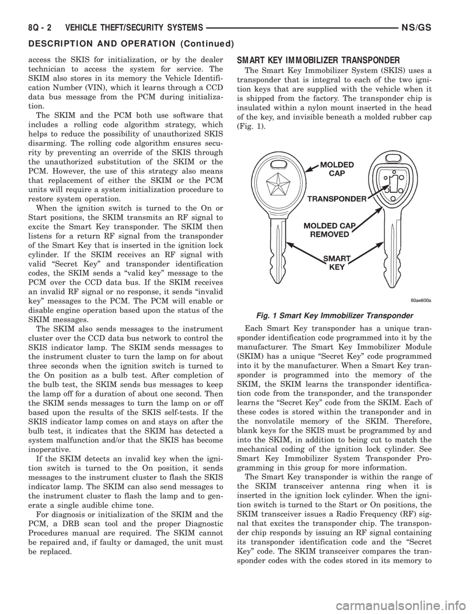
is shipped from the factory. The transponder chip is
insulated within a nylon mount inserted in the head
of the key, and invisible beneath a molded rubber cap
(Fig. 1).
Each Smart Key transponder has a unique tran-
sponder identification code programmed into it by the
manufacturer. The Smart Key Immobilizer Module
(SKIM) has a unique ªSecret Keyº code programmed
into it by the manufacturer. When a Smart Key tran-
sponder is programmed into the memory of the
SKIM, the SKIM learns the transponder identifica-
tion code from the transponder, and the transponder
learns the ªSecret Keyº code from the SKIM. Each of
these codes is stored within the transponder and in
the nonvolatile memory of the SKIM. Therefore,
blank keys for the SKIS must be programmed by and
into the SKIM, in addition to being cut to match the
mechanical coding of the ignition lock cylinder. See
Smart Key Immobilizer System Transponder Pro-
gramming in this group for more information.
The Smart Key transponder is within the range of
the SKIM transceiver antenna ring when it is
inserted in the ignition lock cylinder. When the igni-
tion switch is turned to the Start or On positions, the
SKIM transceiver issues a Radio Frequency (RF) sig-
nal that excites the transponder chip. The transpon-
der chip responds by issuing an RF signal containing
its transponder identification code and the ªSecret
Keyº code. The SKIM transceiver compares the tran-
sponder codes with the codes stored in its memory to
Fig. 1 Smart Key Immobilizer Transponder
8Q - 2 VEHICLE THEFT/SECURITY SYSTEMSNS/GS
DESCRIPTION AND OPERATION (Continued)
Page 1489 of 1938

(4) Low pressure in R and 1 but correct pressure
in 2 indicates rear servo circuit leakage.
(5) Low line pressure in all positions indicates a
defective pump, a clogged filter, or a stuck pressure
regulator valve.
GOVERNOR PRESSURE
Test only if transaxle shifts at wrong vehicle
speeds when throttle cable is correctly adjusted.
(1) Connect a 0-150 psi pressure gauge to governor
pressure take-off point. It is located at lower right
side of case, below differential cover.
(2) Operate transaxle in third gear to read pres-
sures. The governor pressure should respond
smoothly to changes in mph and should return to 0
to 3 psi when vehicle is stopped. High pressure at
standstill (above 3 psi) will prevent the transaxle
from downshifting.
THROTTLE PRESSURE
No gauge port is provided for throttle pressure.
Incorrect throttle pressure should be suspected if
part throttle upshift speeds are either delayed or
occur too early in relation to vehicle speeds. Engine
runaway on shifts can also be an indicator of low
throttle pressure setting, or misadjusted throttle
cable.
In no case should throttle pressure be adjusted
until the transaxle throttle cable adjustment has
been verified to be correct.
CLUTCH AND SERVO AIR PRESSURE TESTS
A no drive condition might exist even with correct
fluid pressure, because of inoperative clutches or
bands. The inoperative units, clutches, bands, and
servos can be located through a series of tests. This
is done by substituting air pressure for fluid pressure
(Fig. 4) .
The front and rear clutches, kickdown servo, and
low-reverse servo may be tested by applying air pres-
sure to their respective passages. To make air pres-
sure tests, proceed as follows:
NOTE: Compressed air supply must be free of all
dirt or moisture. Use a pressure of 30 psi.
Remove oil pan and valve body. Refer to Valve
Body for removal procedure.
FRONT CLUTCH
Apply air pressure to front clutch apply passage
and listen for a dull thud which indicates that front
clutch is operating. Hold air pressure on for a few
seconds and inspect system for excessive oil leaks.
REAR CLUTCH
Apply air pressure to rear clutch apply passage
and listen for a dull thud which indicates that rear
clutch is operating. Also inspect for excessive oil
leaks. If a dull thud cannot be heard in the clutches,
place finger tips on clutch housing and again apply
air pressure. Movement of piston can be felt as the
clutch is applied.
KICKDOWN SERVO (FRONT)
Direct air pressure into KICKDOWN SERVO ON
passage. Operation of servo is indicated by a tighten-
ing of front band. Spring tension on servo piston
should release the band.
LOW AND REVERSE SERVO (REAR)
Direct air pressure into LOW-REVERSE SERVO
APPLY passage. Operation of servo is indicated by a
tightening of rear band. Spring tension on servo pis-
ton should release the band.
If clutches and servos operate properly, no upshift
indicates that a malfunction exists in the valve body.
FLUID LEAKAGE-TRANSAXLE TORQUE
CONVERTER HOUSING AREA
(1) Check for source of leakage.
(2) Since fluid leakage near the torque converter
area may be from an engine oil leak, the area should
be checked closely. Factory fill fluid is dyed red and,
therefore, can be distinguished from engine oil.
(3) Prior to removing the transaxle, perform the
following checks:
(4) When leakage is determined to originate from
the transaxle, check fluid level prior to removal of
the transaxle and torque converter.
(5) High oil level can result in oil leakage out the
vent in the dipstick. If the fluid level is high, adjust
to proper level.
(6) After performing this operation, inspect for
leakage. If a leak persists, perform the following
operation on the vehicle. This will determine if the
torque converter or transaxle is leaking.
TORQUE CONVERTER LEAKAGE
Possible sources of torque converter leakage are:
²Torque converter weld leaks at the outside diam-
eter (peripheral) weld.
²Torque converter hub weld.
²Torque converter impeller shell cracked adjacent
to hub.
²At drive lug welds.
NOTE: Hub weld is inside and not visible. Do not
attempt to repair. Replace torque converter.
NSTRANSAXLE AND POWER TRANSFER UNIT 21 - 15
DIAGNOSIS AND TESTING (Continued)
Page 1551 of 1938

(4) Reverse and LR clutch pressure should read
165 to 235 psi.
(5) This test checks the reverse clutch hydraulic
circuit.
TEST RESULT INDICATIONS
(1) If proper line pressure is found in any one test,
the pump and pressure regulator are working prop-
erly.
(2) Low pressure in all positions indicates a defec-
tive pump, a clogged filter, or a stuck pressure regu-
lator valve.
(3) Clutch circuit leaks are indicated if pressures
do not fall within the specified pressure range.
(4) If the overdrive clutch pressure is greater than
5 psi in Step 4 of Test Three, a worn reaction shaft
seal ring or a defective solenoid assembly is indi-
cated.
(5) If the underdrive clutch pressure is greater
than 5 psi in Step 4 of Test 2A, a defective solenoid
assembly or TCM is the cause.
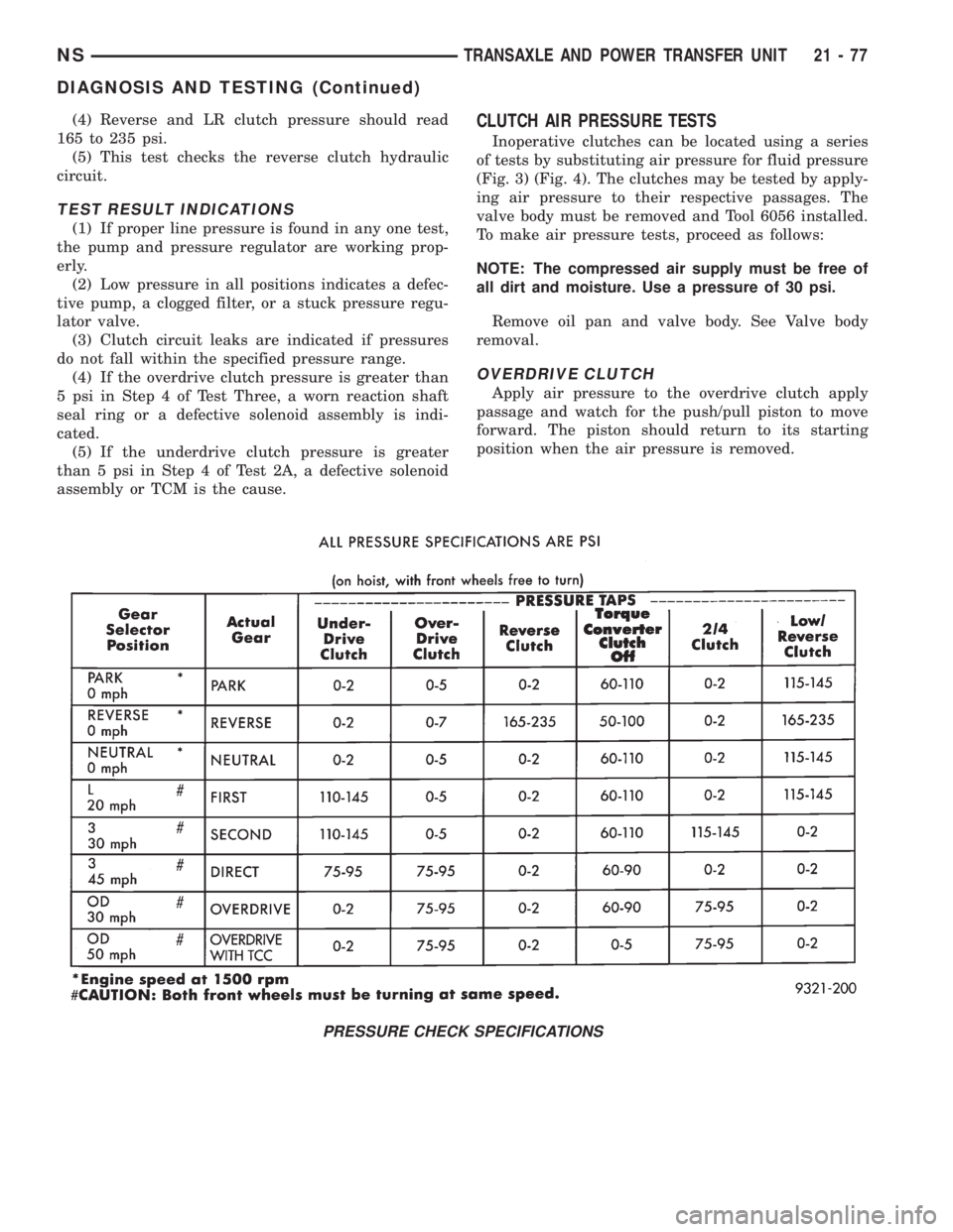
CLUTCH AIR PRESSURE TESTS
Inoperative clutches can be located using a series
of tests by substituting air pressure for fluid pressure
(Fig. 3) (Fig. 4). The clutches may be tested by apply-
ing air pressure to their respective passages. The
valve body must be removed and Tool 6056 installed.
To make air pressure tests, proceed as follows:
NOTE: The compressed air supply must be free of
all dirt and moisture. Use a pressure of 30 psi.
Remove oil pan and valve body. See Valve body
removal.
OVERDRIVE CLUTCH
Apply air pressure to the overdrive clutch apply
passage and watch for the push/pull piston to move
forward. The piston should return to its starting
position when the air pressure is removed.
PRESSURE CHECK SPECIFICATIONS
NSTRANSAXLE AND POWER TRANSFER UNIT 21 - 77
DIAGNOSIS AND TESTING (Continued)