check oil CHRYSLER VOYAGER 1996 Service Manual
[x] Cancel search | Manufacturer: CHRYSLER, Model Year: 1996, Model line: VOYAGER, Model: CHRYSLER VOYAGER 1996Pages: 1938, PDF Size: 55.84 MB
Page 19 of 1938
MAINTENANCE SCHEDULES
INDEX
page page
GENERAL INFORMATION
INTRODUCTION......................... 3
SCHEDULE ± A.......................... 3SCHEDULE ± B.......................... 4
UNSCHEDULED INSPECTION............... 3
GENERAL INFORMATION
INTRODUCTION
Service and maintenance procedures for compo-
nents and systems listed in Schedule ± A or B can be
found by using the Group Tab Locator index at the
front of this manual. If it is not clear which group
contains the information needed, refer to the index at
the back of this manual.
There are two maintenance schedules that show
proper service based on the conditions that the vehi-
cle is subjected to.
Schedule ±A, lists scheduled maintenance to be
performed when the vehicle is used for general trans-
portation.
Schedule ±B, lists maintenance intervals for vehi-
cles that are operated under the conditions listed at
the beginning of the Maintenance Schedule section.
Use the schedule that best describes your driving
conditions.
Where time and mileage are listed, follow the
interval that occurs first.
UNSCHEDULED INSPECTION
At Each Stop for Fuel
²Check engine oil level, add as required.
²Check windshield washer solvent and add if
required.
Once a Month
²Check tire pressure and look for unusual wear
or damage.
²Inspect battery and clean and tighten terminals
as required.
²Check fluid levels of coolant reservoir, brake
master cylinder, power steering and transaxle and
add as needed.
²Check all lights and all other electrical items for
correct operation.
²Check rubber seals on each side of the radiator
for proper fit.
At Each Oil Change
²Inspect exhaust system.
²Inspect brake hoses
²Inspect the CV joints and front suspension com-
ponents
²Rotate the tires at each oil change interval
shown on Schedule ± A (7,500 miles) or every other
interval shown on Schedule ± B (6,000 miles).
²Check the coolant level, hoses, and clamps.
²If your mileage is less than 7,500 miles (12 000
km) yearly, replace the engine oil filter at each oil
change.
²Replace engine oil filter on 2.4L engines.
SCHEDULE ± A
7,500 Miles (12 000 km) or at 6 months
²Change engine oil.
15,000 Miles (24 000 km) or at 12 months
²Change engine oil.
²Replace engine oil filter.
22,500 Miles (36 000 km) or at 18 months
²Change engine oil.
²Inspect brake linings.
30,000 Miles (48 000 km) or at 24 months
²Change engine oil.
²Change automatic transmission fluid.
²Replace engine oil filter.
²Replace air cleaner element.
²Inspect tie rod ends and boot seals.
37,500 Miles (60 000 km) or at 30 months
²Change engine oil.
45,000 Miles (72 000 km) or at 36 months
²Change engine oil.
²Replace engine oil filter.
²Inspect brake linings.
²Flush and replace engine coolant at 36 months,
regardless of mileage.
NSLUBRICATION AND MAINTENANCE 0 - 3
Page 20 of 1938
52,500 Miles (84 000 km) or at 42 months
²Change engine oil.
²Flush and replace engine coolant if not done at
36 months.
60,000 Miles (96 000 km) or at 48 months
²Change engine oil.
²Replace engine oil filter.
²Replace air cleaner element.
²Check PCV valve and replace, if necessary.
*
²Inspect serpentine drive belt, replace if neces-
sary.
²Inspect tie rod ends and boot seals.
67,500 Miles (108 000 km) or at 54 months
²Change engine oil.
²Inspect brake linings.
75,000 Miles (120 000 km) or at 60 months
²Change engine oil.
²Replace engine oil filter.
²Inspect serpentine drive belt, replace if neces-
sary. This maintenance is not required if belt was
previously replaced.
²Flush and replace engine coolant if it has been
30,000 miles (48 000 km) or 24 months since last
change.
82,500 Miles (132 000 km) or at 66 months
²Change engine oil.
²Flush and replace engine coolant if it has been
30,000 miles (48 000 km) or 24 months since last
change.
90,000 Miles (144 000 km) or at 72 months
²Change engine oil.
²Replace engine oil filter.
²Replace air cleaner element.
²Check PCV valve and replace, if necessary.
Not required if previously changed. *
²Inspect serpentine drive belt, replace if neces-
sary. This maintenance is not required if belt was
previously replaced.
²Inspect tie rod ends and boot seals.
²Inspect brake linings.
97,500 Miles (156 000 km) or at 78 months
²Change engine oil.
100,000 Miles (160,000 km)
²Replace spark plugs on 3.3L and 3.8L
engines.
²Replace ignition cables on 3.3L and 3.8L
engines.
105,000 Miles (168 000 km) or at 84 months
²Change engine oil.
²Replace engine oil filter.
²Inspect serpentine drive belt, replace if neces-
sary. This maintenance is not required if belt was
previously replaced.
²Flush and replace engine coolant if it has been
30,000 miles (48 000 km) or 24 months since last
change.
112,500 Miles (180 000 km) or at 90 months
²Change engine oil.
²Inspect brake linings.
²Flush and replace engine coolant if it has been
30,000 miles (48 000 km) or 24 months since last
change.
120,000 Miles (192 000 km) or at 96 months
²Change engine oil.
²Replace engine oil filter.
²Replace automatic transmission fluid.
²Replace engine air cleaner element.
²Check and replace PCV valve, if necessary.
*
²Inspect serpentine drive belt. Not required if
replaced at 75,000, 90,000 or 105,000 miles.
²Inspect tie rod ends and boot seals.
* This maintenance is recommended by Chrysler to
the owner but is not required to maintain the war-
ranty on the PCV valve.
** If California vehicle, this maintenance is recom-
mended by Chrysler to the owner but is not required
to maintain the warranty of the timing belt.
SCHEDULE ± B
3,000 Miles (5 000 km)
²Change engine oil.
6,000 Miles (10 000 km)
²Change engine oil.
²Replace engine oil filter.
9,000 Miles (14 000 km)
²Change engine oil.
²Inspect brake linings.
12,000 Miles (19 000 km)
²Change engine oil.
²Replace engine oil filter.
15,000 Miles (24 000 km)
²Change engine oil.
²Inspect air cleaner element. Replace as
necessary.
0 - 4 LUBRICATION AND MAINTENANCENS
GENERAL INFORMATION (Continued)
Page 21 of 1938
²Drain and refill automatic transmission fluid
and replace filter. Adjust bands, if so equipped. (See
note)
²Change AWD powertransfer fluid unit.
18,000 Miles (29 000 km)
²Change engine oil.
²Replace engine oil filter.
²Inspect brake linings.
21,000 Miles (34 000 km)
²Change engine oil.
²Check AWD overrunning clutch and rear carrier
fluid.
24,000 Miles (38 000 km)
²Change engine oil.
²Replace engine oil filter.
27,000 Miles (43 000 km)
²Change engine oil.
²Inspect brake linings.
30,000 Miles (48 000 km)
²Change engine oil.
²Replace engine oil filter.
²Replace air cleaner element.
²Inspect PCV valve. Replace as necessary. *
²Drain and refill automatic transmission fluid
and replace filter. Adjust bands, if so equipped. (See
note)
²Change AWD power transfer unit fluid.
²Inspect tie rod ends and boot seals.
33,000 Miles (53 000 km)
²Change engine oil.
36,000 Miles (58 000 km)
²Change engine oil.
²Replace engine oil filter.
²Inspect brake linings.
39,000 Miles (62 000 km)
²Change engine oil.
42,000 Miles (67 000 km)
²Change engine oil.
²Replace engine oil filter.
²Change AWD overrunning clutch and rear car-
rier fluid.
45,000 Miles (72 000 km)
²Change engine oil.
²Inspect air cleaner element. Replace as
necessary.²Drain and refill automatic transmission fluid
and replace filter. Adjust bands, if so equipped. (See
note)
²Inspect brake linings.
²Change AWD power transfer unit fluid.
48,000 Miles (77 000 km)
²Change engine oil.
²Replace engine oil filter.
51,000 Miles (82 000 km)
²Change engine oil.
²Flush and replace engine coolant.
54,000 Miles (86 000 km)
²Change engine oil.
²Replace engine oil filter.
²Inspect brake linings.
57,000 Miles (91 000 km)
²Change engine oil.
60,000 Miles (96 000 km)
²Change engine oil.
²Replace engine oil filter.
²Replace air cleaner element.
²Inspect PCV valve, replace if necessary. *
²Inspect serpentine drive belt, replace if neces-
sary.
²Drain and refill automatic transmission fluid
and replace filter. Adjust bands, if so equipped. (See
note)
²Change AWD power transfer unit fluid.
²Inspect tie rod ends and boot seals.
63,000 Miles (101 000 km)
²Change engine oil.
²Change AWD overrunning clutch and rear car-
rier fluid.
²Inspect brake linings.
66,000 Miles (106 000 km)
²Change engine oil.
²Replace engine oil filter.
69,000 Miles (110 000 km)
²Change engine oil.
72,000 Miles (115 000 km)
²Change engine oil.
²Replace engine oil filter.
²Inspect brake linings.
75,000 Miles (120 000 km)
²Change engine oil.
²Inspect air cleaner element. Replace as
necessary.
NSLUBRICATION AND MAINTENANCE 0 - 5
GENERAL INFORMATION (Continued)
Page 22 of 1938
²Replace spark plugs.
²Replace ignition cables.
²Inspect serpentine drive belt, replace if neces-
sary. This maintenance is not required if belt was
previously replaced.
²Drain and refill automatic transaxle fluid and
replace filter. Adjust band, if so equipped. (See note)
²Change AWD power transfer unit fluid.
78,000 Miles (125 000 km)
²Change engine oil.
²Replace engine oil filter.
81,000 Miles (130 000 km)
²Change engine oil.
²Inspect brake linings.
²Flush and replace engine coolant.
84,000 Miles (134 000 km)
²Change engine oil.
²Replace engine oil filter.
²Change AWD overrunning clutch and rear car-
rier fluid.
87,000 Miles (139 000 km)
²Change engine oil.
90,000 Miles (144 000 km)
²Change engine oil.
²Replace engine oil filter.
²Replace air cleaner element.
²Check PCV valve and replace if necessary.
Not required if previously changed. *
²Inspect serpentine drive belt, replace if neces-
sary. This maintenance is not required if belt was
previously replaced.
²Drain and refill automatic transmission fluid
and replace filter. Adjust bands, if so equipped. (See
note)
²Change AWD power transfer unit fluid.
²Inspect tie rod ends and boot seals.
²Inspect brake linings.
93,000 Miles (149 000 km)
²Change engine oil.
96,000 Miles (154 000 km)
²Change engine oil.
²Replace engine oil filter.
99,000 Miles (158 000 km)
²Change engine oil.
²Inspect brake linings.
102,000 Miles (163 000 km)
²Change engine oil.
²Replace engine oil filter.
105,000 Miles (168 000 km)
²Change engine oil.
²Inspect air cleaner element. Replace as
necessary.
²Inspect serpentine drive belt, replace if neces-
sary. This maintenance is not required if belt was
previously replaced.
²Drain and refill automatic transmission fluid
and filter. Adjust bands, if so equipped. (See note)
²Change AWD power transfer unit fluid.
²Change AWD overrunning clutch and rear car-
rier fluid.
108,000 Miles (173 000 km)
²Change engine oil.
²Replace engine oil filter.
²Inspect brake linings.
111,000 Miles (178 000 km)
²Change engine oil.
²Flush and replace engine coolant.
114,000 Miles (182 000 km)
²Change engine oil.
²Replace engine oil filter.
117,000 Miles (187 000 km)
²Change engine oil.
²Inspect brake linings.
120,000 Miles (192 000 km)
²Change engine oil.
²Replace engine oil filter.
²Replace air cleaner element.
²Inspect PCV valve. Replace as necessary. *
²Inspect serpentine drive belt. Not required if
replaced at 75,000, 90,000 or 105,000 miles.
²Drain and refill automatic transmission fluid
and replace filter. Adjust bands, if so equipped.
²Change AWD power transfer unit fluid.
²Inspect tie rod ends and boot seals.
* This maintenance is recommended by Chrysler to
the owner but is not required to maintain the war-
ranty on the PCV valve.
** If California vehicle, this maintenance is recom-
mended by Chrysler to the owner but is not required
to maintain the warranty of the timing belt.
NOTE: Operating vehicle more than 50% in heavy
traffic during hot weather, above 90ÉF (32ÉC), using
vehicle for police, taxi, limousine type operation or
trailer towing require the more frequent transaxle
service noted in Schedule ± B. Perform these ser-
vices if vehicle is usually operated under these con-
ditions.
Inspection and service should also be performed
anytime a malfunction is observed or suspected.
0 - 6 LUBRICATION AND MAINTENANCENS
GENERAL INFORMATION (Continued)
Page 28 of 1938
MAINTENANCE SCHEDULES
INDEX
page page
GENERAL INFORMATION
MAINTENANCE SCHEDULE............... 2
MAINTENANCE SCHEDULEÐ
DIESEL ENGINE....................... 2SCHEDULEÐA (DIESEL).................. 2
SCHEDULEÐB (DIESEL).................. 3
UNSCHEDULED INSPECTION.............. 2
GENERAL INFORMATION
MAINTENANCE SCHEDULE
Refer to the 1998 GS Service Manual for Gasoline
Engine and non-engine related Maintenance Sched-
ules.
MAINTENANCE SCHEDULEÐDIESEL ENGINE
The following are engine related Maintenance
items which are unique to Diesel engine-equipped
vehicles. Refer to the 1998 GS Service Manual for
Gasoline Engine and non-engine related Maintenance
Schedules.
The service intervals are based on odometer read-
ings in kilometers. There are two maintenance sched-
ules that show proper service intervals. Use the
schedule that best describes the conditions the vehi-
cle is operated under.Schedule-Alists all the sched-
uled maintenance to be performed under normal
operating conditions.Schedule-Bis the schedule for
vehicles that are operated under one or more of the
following conditions:
²Day and night temperatures are below freezing.
²Stop and go driving.
²Long periods of engine idling.
²Driving in dusty conditions.
²Short trips of less than 5 miles.
²Operation at sustained high speeds during hot
weather above 32ÉC (90ÉF).
²Taxi, police or delivery service.
²Trailer towing.
UNSCHEDULED INSPECTION
At Each Stop for Fuel
²Check engine oil level, add as required.
²Check windshield washer solvent and add if
required.
Once a Month
²Check tire pressure and look for unusual wear
or damage.
²Inspect battery and clean and tighten terminals
as required.²Check fluid levels of coolant reservoir, brake
master cylinder, power steering and transaxle and
add as needed.
²Check all lights and all other electrical items for
correct operation.
²Check rubber seals on each side of the radiator
for proper fit.
At Each Oil Change
²Inspect exhaust system.
²Inspect brake hoses
²Inspect the CV joints and front suspension com-
ponents
²Rotate the tires at each oil change interval
shown on ScheduleÐA (7,500 miles) or every other
interval shown on ScheduleÐ B (6,000 miles).
²Check the coolant level, hoses, and clamps.
²If your mileage is less than 7,500 miles (12 000
km) yearly, replace the engine oil filter at each oil
change.
²Replace engine oil filter.
SCHEDULEÐA (DIESEL)
1 000 KM
²Change engine oil.
²Change engine oil filter.
²Check all fluid levels.
²Check correct torque, intake manifold mounting
nuts.
²Check correct torque, exhaust manifold mount-
ing nuts.
²Check correct torque, turbocharger mounting
nuts.
²Check correct torque, water manifold bolts.
10 000 KM
²Change engine oil.
²Change engine oil filter.
20 000 KM
²Change engine oil.
²Change engine oil filter.
²Replace air filter element.
0 - 2 LUBRICATION AND MAINTENANCENS/GS
Page 29 of 1938
²Check drive belt tension.
²Check glow plug operation.
30 000 KM
²Change engine oil.
²Change engine oil filter.
40 000 KM
²Change engine oil.
²Change engine oil filter.
²Replace air filter element.
²Check drive belt tension.
²Check glow plug operation.
²Replace fuel filter/water separator element.**
50 000 KM
²Change engine oil.
²Change engine oil filter.
60 000 KM
²Change engine oil.
²Change engine oil filter.
²Replace air filter element.
²Check glow plug operation.
²Replace drive belt.
²Check engine smoke.
²Replace engine coolant.
70 000 KM
²Change engine oil.
²Change engine oil filter.
80 000 KM
²Change engine oil.
²Change engine oil filter.
²Replace air filter element.
²Check drive belt tension.
²Check glow plug operation.
²Replace fuel filter/water separator element.**
90 000 KM
²Change engine oil.
²Change engine oil filter.
100 000 KM
²Change engine oil.
²Change engine oil filter.
²Replace air filter element.
²Check drive belt tension.
²Check glow plug operation.
EVERY 40 000 KM AFTER 80 000 KM
²Replace fuel filter/water separator element.**
**The fuel filter/water separator element should be
replaced once a year if the vehicle is driven less than
40 000 km annually or if power loss from fuel star-
vation is detected.
EVERY 10 000 KM AFTER 100 000 KM
²Change engine oil.
²Change engine oil filter.
EVERY 20 000 KM AFTER 100 000 KM
²Change engine oil.
²Change engine oil filter.
²Replace air filter element.
²Check drive belt tension.
²Check glow plug operation.
SCHEDULEÐB (DIESEL)
500 KM
²Check correct torque, intake manifold mounting
nuts.
²Check correct torque, exhaust manifold mount-
ing nuts.
²Check correct torque, turbocharger mounting
nuts.
²Check correct torque, water manifold bolts.
1 000 KM
²Change engine oil.
²Change engine oil filter.
²Check all fluid levels.
5 000 KM
²Change engine oil.
²Change engine oil filter.
10 000 KM
²Change engine oil.
²Change engine oil filter.
²Replace air filter element.
²Check drive belt tension.
²Check glow plug operation.
15 000 KM
²Change engine oil.
²Change engine oil filter.
20 000 KM
²Change engine oil.
²Change engine oil filter.
²Replace air filter element.
²Check drive belt tension.
²Check glow plug operation.
25 000 KM
²Change engine oil.
²Change engine oil filter.
30 000 KM
²Change engine oil.
²Change engine oil filter.
²Replace air filter element.
NS/GSLUBRICATION AND MAINTENANCE 0 - 3
GENERAL INFORMATION (Continued)
Page 30 of 1938
²Check glow plug operation.
²Replace drive belt.
²Check engine smoke.
²Replace engine coolant.
35 000 KM
²Change engine oil.
²Change engine oil filter.
²Change MTX Fluid
40 000 KM
²Change engine oil.
²Change engine oil filter.
²Replace air filter element.
²Check drive belt tension.
²Check glow plug operation.
²Diesel engines onlyÐReplace fuel filter/water
separator element.
45 000 KM
²Change engine oil.
²Change engine oil filter.
50 000 KM
²Change engine oil.
²Change engine oil filter.
²Replace air filter element.
²Check drive belt tension.
²Check glow plug operation.
55 000 KM
²Change engine oil.
²Change engine oil filter.
60 000 KM
²Change engine oil.
²Change engine oil filter.
²Replace air filter element.
²Check drive belt tension.
²Check glow plug operation.
²Diesel engines onlyÐReplace fuel filter/water
separator element.
65 000 KM
²Change engine oil.
²Change engine oil filter.
70 000 KM
²Change engine oil.
²Change engine oil filter.
²Replace air filter element.
²Check drive belt tension.
²Check glow plug operation.
²Change MTX fluid
75 000 KM
²Change engine oil.
²Change engine oil filter.
80 000 KM
²Change engine oil.
²Change engine oil filter.
²Replace air filter element.
²Check glow plug operation.
²Replace drive belt.
²Check engine smoke.
²Replace engine coolant.
85 000 KM
²Change engine oil.
²Change engine oil filter.
90 000 KM
²Change engine oil.
²Change engine oil filter.
²Replace air filter element.
²Check drive belt tension.
²Check glow plug operation.
95 000 KM
²Change engine oil.
²Change engine oil filter.
100 000 KM
²Change engine oil.
²Change engine oil filter.
²Replace air filter element.
²Check drive belt tension.
²Check glow plug operation.
²Diesel engines onlyÐReplace fuel filter/water
separator element.
²Change MTX fluid
EVERY 5 000 KM AFTER 100 000 KM
²Change engine oil.
²Change engine oil filter.
EVERY 10 000 KM AFTER 100 000 KM
²Change engine oil.
²Change engine oil filter.
²Replace air filter element.
²Check drive belt tension.
²Check glow plug operation.
EVERY 20 000 KM AFTER 100 000 KM
²Diesel engines onlyÐReplace fuel filter/water
separator element.
EVERY 35 000 KM AFTER 100 000 KM
²Change MTX fluid
0 - 4 LUBRICATION AND MAINTENANCENS/GS
GENERAL INFORMATION (Continued)
Page 44 of 1938
STEERING KNUCKLE
The front suspension knuckle is not a repairable
component of the vehicles front suspensionIT MUST
BE REPLACED.If bent, broken or damaged in any
way, do not attempt to straighten or repair the steer-
ing knuckle.
Service replacement of the front hub/bearing
assembly can be done with the front steering knuckle
remaining on the vehicle.
LOWER CONTROL ARM
If damaged, the lower control arm casting is ser-
viced only as a complete component. Inspect lower
control arm for signs of damage from contact with
the ground or road debris. If lower control arm shows
any sign of damage, inspect lower control arm for
distortion.Do not attempt to repair or straighten
a broken or bent lower control arm.
The serviceable components of the lower control
arm are: the ball joint assembly, ball joint assembly
grease seal and control arm bushings. Inspect both
control arm bushings for severe deterioration, and
replace if required. Inspect ball joint per inspection
procedure in this section of the service manual and
replace if required. Service procedures to replace
these components are detailed in the specific compo-
nent removal and installation sections in this group
of the service manual.
BALL JOINT (LOWER)
With the weight of the vehicle resting on the road
wheels, grasp the grease fitting as shown in (Fig. 5)
and with no mechanical assistance or added force
attempt to rotate the grease fitting.
If the ball joint is worn the grease fitting will
rotate easily. If movement is noted, replacement of
the ball joint is recommended.
STABILIZER BAR
Inspect for broken or distorted sway bar bushings,
bushing retainers, and worn or damaged sway bar to
strut attaching links. If sway bar to front suspension
cradle bushing replacement is required, bushing can
be removed from sway bar by opening slit and peel-
ing bushing off sway bar.
HUB AND BEARING ASSEMBLY
The condition of the front hub and bearing assem-
bly is diagnosed using the inspection and testing pro-
cedure detailed below.
The bearing contained in the Unit III front hub/
bearing assembly will produce noise and vibration
when worn or damaged. The noise will generally
change when the bearings are loaded. A road test of
the vehicle is normally required to determine the
location of a worn or damaged bearing.
Find a smooth level road surface and bring the
vehicle up to a constant speed. When vehicle is at a
constant speed, swerve the vehicle back and forth
from the left and to the right. This will load and
unload the bearings and change the noise level.
Where axle bearing damage is slight, the noise is
usually not noticeable at speeds above 30 m.p.h..
SERVICE PROCEDURES
SUSPENSION CRADLE THREAD REPAIR
PROCEDURE
WARNING: When performing this procedure use
only the thread inserts which are specified in the
Mopar Parts Catalog for this repair procedure.
These thread inserts have been specifically devel-
oped for this application and use of other types of
thread inserts can result in an inferior long term
repair.
The threaded holes in the front suspension cradle,
if damaged, can repaired by installing a Heli-Coilt
thread insert.
The threaded holes that are repairable using the
thread insert, are the lower control arm rear bushing
retainer mounting bolt holes, routing bracket attach-
ing locations for the power steering hoses, and brake
hose attachment holes.
This repair procedure now allows the threaded
holes in the suspension crossmember to be repaired,
eliminating the need to replace the crossmember if
damage occurs to one of the threaded holes.
The thread inserts for this application are specified
by part number in the Mopar Parts Catalog.Do not
use a substitute thread insert.
The specific tools and equipment required to install
the thread insert are listed below. Refer to the
Fig. 5 Checking Ball Joint Wear
2 - 12 SUSPENSIONNS
DIAGNOSIS AND TESTING (Continued)
Page 102 of 1938
SERVICE PROCEDURES
MASTER CYLINDER FLUID LEVEL CHECK
Check master cylinder reservoir fluid level a mini-
mum of twice annually.
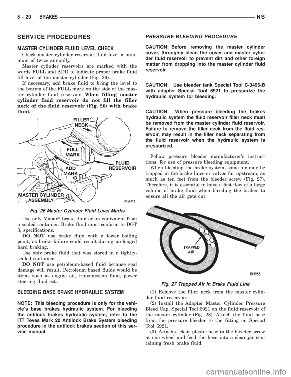
Master cylinder reservoirs are marked with the
words FULL and ADD to indicate proper brake fluid
fill level of the master cylinder (Fig. 26).
If necessary, add brake fluid to bring the level to
the bottom of the FULL mark on the side of the mas-
ter cylinder fluid reservoir.When filling master
cylinder fluid reservoir do not fill the filler
neck of the fluid reservoir (Fig. 26) with brake
fluid.
Use only Mopartbrake fluid or an equivalent from
a sealed container. Brake fluid must conform to DOT
3, specifications.
DO NOTuse brake fluid with a lower boiling
point, as brake failure could result during prolonged
hard braking.
Use only brake fluid that was stored in a tightly-
sealed container.
DO NOTuse petroleum-based fluid because seal
damage will result. Petroleum based fluids would be
items such as engine oil, transmission fluid, power
steering fluid ect.
BLEEDING BASE BRAKE HYDRAULIC SYSTEM
NOTE: This bleeding procedure is only for the vehi-
cle's base brakes hydraulic system. For bleeding
the antilock brakes hydraulic system, refer to the
ITT Teves Mark 20 Antilock Brake System bleeding
procedure in the antilock brakes section of this ser-
vice manual.
PRESSURE BLEEDING PROCEDURE
CAUTION: Before removing the master cylinder
cover, throughly clean the cover and master cylin-
der fluid reservoir to prevent dirt and other foreign
matter from dropping into the master cylinder fluid
reservoir.
CAUTION: Use bleeder tank Special Tool C-3496-B
with adapter Special Tool 6921 to pressurize the
hydraulic system for bleeding.
CAUTION: When pressure bleeding the brakes
hydraulic system the fluid reservoir filler neck must
be removed from the master cylinder fluid reservoir.
Failure to remove the filler neck from the fluid res-
ervoir, may result in the filler neck separating from
the fluid reservoir when the hydraulic system is
pressurized.
Follow pressure bleeder manufacturer's instruc-
tions, for use of pressure bleeding equipment.
When bleeding the brake system, some air may be
trapped in the brake lines or valves far upstream, as
much as ten feet from the bleeder screw (Fig. 27).
Therefore, it is essential to have a fast flow of a large
volume of brake fluid when bleeding the brakes to
ensure all the air gets out.
(1) Remove the filler neck from the master cylin-
der fluid reservoir.
(2) Install the Adapter Master Cylinder Pressure
Bleed Cap, Special Tool 6921 on the fluid reservoir of
the master cylinder (Fig. 28). Attach the fluid hose
from the pressure bleeder to the fitting on Special
Tool 6921.
(3) Attach a clear plastic hose to the bleeder screw
at one wheel and feed the hose into a clear jar con-
taining fresh brake fluid.
Fig. 26 Master Cylinder Fluid Level Marks
Fig. 27 Trapped Air In Brake Fluid Line
5 - 20 BRAKESNS
Page 160 of 1938
REAR DRUM BRAKE WHEEL CYLINDER
With brake drums removed, inspect the wheel cyl-
inder boots for evidence of a brake fluid leak. Visu-
ally check the boots for cuts, tears, or heat cracks. If
any of these conditions exist, the wheel cylinders
should be completely cleaned, inspected and new
parts installed.
If a wheel cylinder is leaking and the brake lining
material is saturated with brake fluid, the brake
shoes must be replaced.
BRAKE HOSE AND BRAKE LINES INSPECTION
Flexible rubber hose is used at both front brakes
and at the rear axle. Inspection of brake hoses
should be performed whenever the brake system is
serviced and every 7,500 miles or 12 months, which-
ever comes first (every engine oil change). Inspect
hydraulic brake hoses for surface cracking, scuffing,
or worn spots. If the fabric casing of the rubber hose
becomes exposed due to cracks or abrasions in the
rubber hose cover, the hose should be replaced imme-
diately. Eventual deterioration of the hose can take
place with possible burst failure. Faulty installation
can cause twisting, resulting in wheel, tire, or chassis
interference.
The steel brake tubing should be inspected period-
ically for evidence of physical damage or contact with
moving or hot components.
The flexible brake tube sections used on this vehi-
cle in the primary and secondary tubes from the
master cylinder to the ABS hydraulic control unit
connections and the chassis brake tubes between the
hydraulic control unit and the proportioning valve
must also be inspected. This flexible tubing must be
inspected for kinks, fraying and its contact with
other components of the vehicle or contact with the
body of the vehicle.
REAR WHEEL HUB AND BEARING ASSEMBLY
The rear hub and bearing assembly is designed for
the life of the vehicle and should require no mainte-
nance. The following procedure may be used for eval-
uation of bearing condition.
With wheel and brake drum removed, rotate
flanged outer ring of hub. Excessive roughness, lat-
eral play or resistance to rotation may indicate dirt
intrusion or bearing failure. If the rear wheel bear-
ings exhibit these conditions during inspection, the
hub and bearing assembly should be replaced.
Damaged bearing seals and resulting excessive
grease loss may also require bearing replacement.
Moderate grease loss from bearing is considered nor-
mal and should not require replacement of the hub
and bearing assembly.
ADJUSTMENTS
STOP LAMP SWITCH
(1) Remove stop lamp switch from its bracket by
rotating it approximately 30É in a counter-clockwise
direction.
(2) Disconnect wiring harness connector from stop
lamp switch.
(3) Hold stop lamp switch firmly in one hand.
Then using other hand, pull outward on the plunger
of the stop lamp switch until it has ratcheted out to
its fully extended position.
(4) Install the stop lamp switch into the bracket
using the following procedure. Depress the brake
pedal as far down as possible. Then while keeping
the brake pedal depressed, install the stop lamp
switch into the bracket by aligning index key on
switch with slot at top of square hole in mounting
bracket. When switch is fully installed in the square
hole of the bracket, rotate switch clockwise approxi-
mately 30É to lock the switch into the bracket.
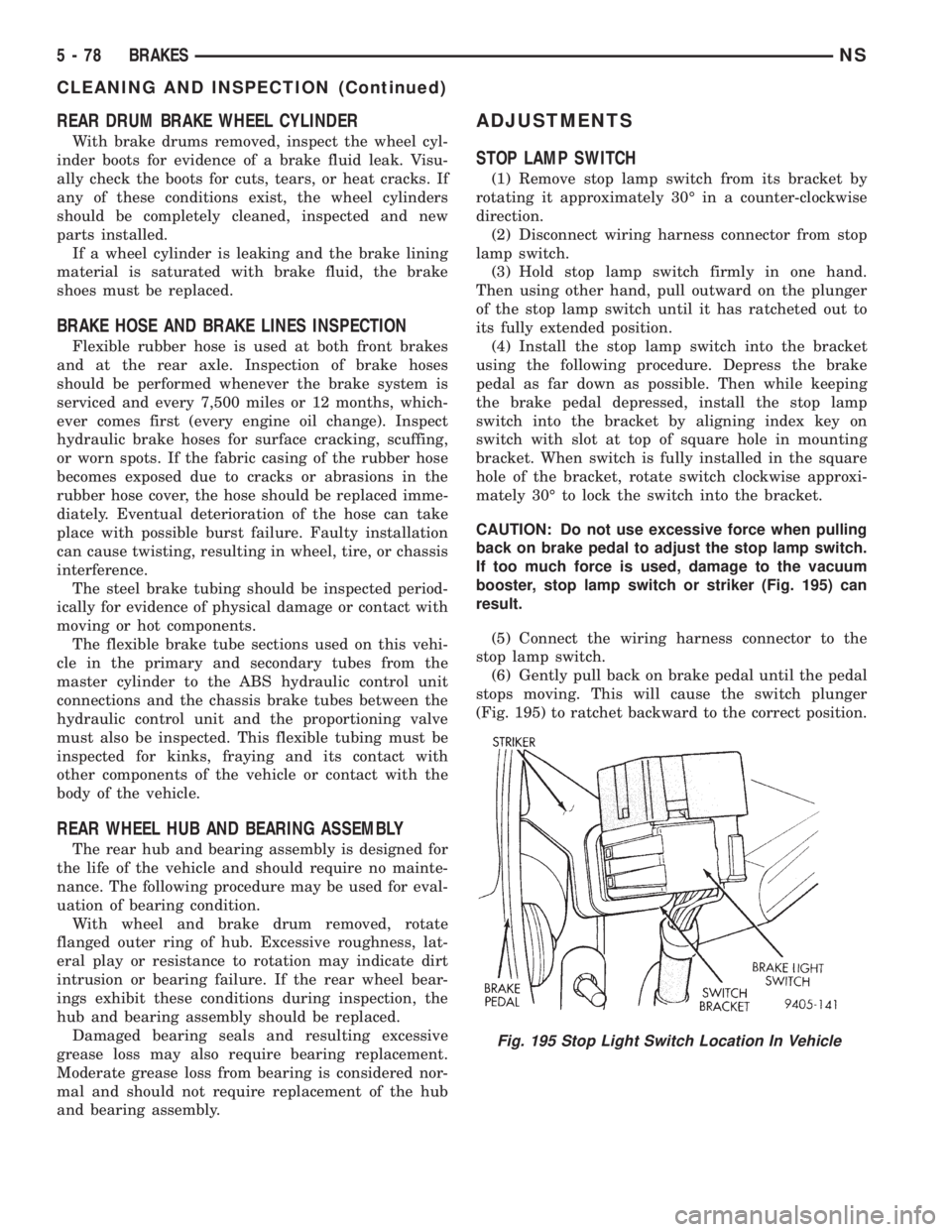
CAUTION: Do not use excessive force when pulling
back on brake pedal to adjust the stop lamp switch.
If too much force is used, damage to the vacuum
booster, stop lamp switch or striker (Fig. 195) can
result.
(5) Connect the wiring harness connector to the
stop lamp switch.
(6) Gently pull back on brake pedal until the pedal
stops moving. This will cause the switch plunger
(Fig. 195) to ratchet backward to the correct position.
Fig. 195 Stop Light Switch Location In Vehicle
5 - 78 BRAKESNS
CLEANING AND INSPECTION (Continued)