injection pump CHRYSLER VOYAGER 1996 Service Manual
[x] Cancel search | Manufacturer: CHRYSLER, Model Year: 1996, Model line: VOYAGER, Model: CHRYSLER VOYAGER 1996Pages: 1938, PDF Size: 55.84 MB
Page 966 of 1938
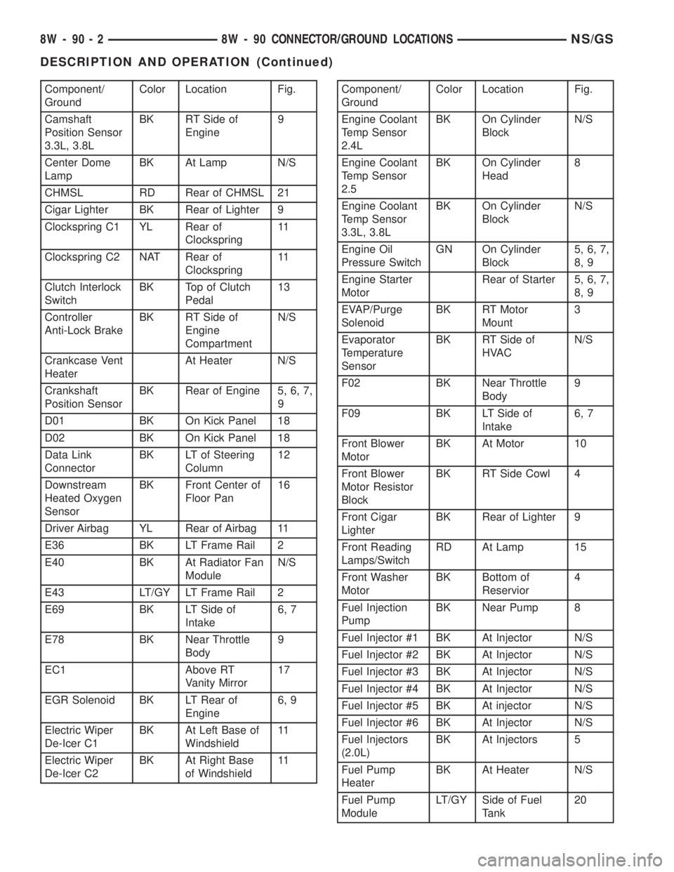
Component/
GroundColor Location Fig.
Camshaft
Position Sensor
3.3L, 3.8LBK RT Side of
Engine9
Center Dome
LampBK At Lamp N/S
CHMSL RD Rear of CHMSL 21
Cigar Lighter BK Rear of Lighter 9
Clockspring C1 YL Rear of
Clockspring11
Clockspring C2 NAT Rear of
Clockspring11
Clutch Interlock
SwitchBK Top of Clutch
Pedal13
Controller
Anti-Lock BrakeBK RT Side of
Engine
CompartmentN/S
Crankcase Vent
HeaterAt Heater N/S
Crankshaft
Position SensorBK Rear of Engine 5, 6, 7,
9
D01 BK On Kick Panel 18
D02 BK On Kick Panel 18
Data Link
ConnectorBK LT of Steering
Column12
Downstream
Heated Oxygen
SensorBK Front Center of
Floor Pan16
Driver Airbag YL Rear of Airbag 11
E36 BK LT Frame Rail 2
E40 BK At Radiator Fan
ModuleN/S
E43 LT/GY LT Frame Rail 2
E69 BK LT Side of
Intake6, 7
E78 BK Near Throttle
Body9
EC1 Above RT
Vanity Mirror17
EGR Solenoid BK LT Rear of
Engine6, 9
Electric Wiper
De-Icer C1BK At Left Base of
Windshield11
Electric Wiper
De-Icer C2BK At Right Base
of Windshield11Component/
GroundColor Location Fig.
Engine Coolant
Temp Sensor
2.4LBK On Cylinder
BlockN/S
Engine Coolant
Temp Sensor
2.5BK On Cylinder
Head8
Engine Coolant
Temp Sensor
3.3L, 3.8LBK On Cylinder
BlockN/S
Engine Oil
Pressure SwitchGN On Cylinder
Block5, 6, 7,
8, 9
Engine Starter
MotorRear of Starter 5, 6, 7,
8, 9
EVAP/Purge
SolenoidBK RT Motor
Mount3
Evaporator
Temperature
SensorBK RT Side of
HVACN/S
F02 BK Near Throttle
Body9
F09 BK LT Side of
Intake6, 7
Front Blower
MotorBK At Motor 10
Front Blower
Motor Resistor
BlockBK RT Side Cowl 4
Front Cigar
LighterBK Rear of Lighter 9
Front Reading
Lamps/SwitchRD At Lamp 15
Front Washer
MotorBK Bottom of
Reservior4
Fuel Injection
PumpBK Near Pump 8
Fuel Injector #1 BK At Injector N/S
Fuel Injector #2 BK At Injector N/S
Fuel Injector #3 BK At Injector N/S
Fuel Injector #4 BK At Injector N/S
Fuel Injector #5 BK At injector N/S
Fuel Injector #6 BK At Injector N/S
Fuel Injectors
(2.0L)BK At Injectors 5
Fuel Pump
HeaterBK At Heater N/S
Fuel Pump
ModuleLT/GY Side of Fuel
Tank20
8W - 90 - 2 8W - 90 CONNECTOR/GROUND LOCATIONSNS/GS
DESCRIPTION AND OPERATION (Continued)
Page 1025 of 1938

8W-95 SPLICE LOCATIONS
INDEX
page page
DESCRIPTION AND OPERATION
INTRODUCTION......................... 1SPLICE LOCATION INDEX.................. 1
SPLICE LOCATIONS (RHD)................ 15
DESCRIPTION AND OPERATION
INTRODUCTION
This section provides illustrations identifying the
general location of the splices in this vehicle. A spliceindex is provided. Use the wiring diagrams in each
section for splice number identification. Refer to the
index for the proper splice number.
SPLICE LOCATION INDEX
Splice Number Location Fig.
BS01 Near Split for Tail Lamps 12
BS02 Near Fuel Tank T/O 12
BS03 Near Instrument Panel T/O 9
BS05 Near Instrument Panel T/O 9
BS05 (2.5L) Near MSA Controller T/O N/S
BS06 Near Instrument Panel T/O 9
BS06 (2.5L) Near MSA Controller T/O N/S
BS08 Near Instrument Panel T/O 9
BS16 Near Right Park Lamp T/O 1
BS17 Near Split for Tail Lamps 12
BS19 Near Horn T/O 1
BS30 (2.5L) Near Generator T/O 5
BS31 Near Left Headlamp Leveling
Motor T/O1
BS31 (2.5L) In BCM T/O 5
BS32 (2.5L) In BCM T/O N/S
BS33 (2.5L) In BCM T/O N/S
BS34 (2.5L) In BCM T/O N/S
BS40 (2.5L) In Engine Harness T/O 5
BS41 (2.5L) In Engine Harness T/O N/S
CS01 Above Right Rear Door 11
CS02 Above Right Rear Door 11
CS03 Right B-Pillar 11
CS04 Right B-Pillar 11
DS01 Near LT Power WDO T/O 10
ES01 In TCM T/O 7
ES01 (2.5L) Near Battery Positive Terminal
T/ON/SSplice Number Location Fig.
ES02 (2.0L) Near Camshaft Position
Sensor T/O3
ES02 (2.4L) Near Fuel Rail T/O 4
ES02 (2.5L) Near Engine Speed Sensor
T/O5
ES02
(3.3L,3.8L)Near Transmission T/O 6
ES03 (2.0L) Near Distributor Coil T/O 2
ES03 (2.4L) Near PDC T/O 4
ES03
(3.3L,3.8L)Near Body Ground T/O 7
ES05 (2.4L) Near Knock Sensor T/O 4
ES05 (2.5L) In Fuel Injection Pump T/O 5
ES05
(3.3L,3.8L)Near Transmission T/O 6
ES06 (2.5L) Near Needle Movement
Sensor T/O5
ES06
(3.3L,3.8L)Near Transmission T/O N/S
ES07 (2.0L) Near Engine Ground T/O 2
ES07 (2.5L) Near Battery Negative
Terminal T/ON/S
ES07 (2.4L) Near Body Ground T/O 4, 7
ES07
(3.3L,3.8L)Near Battery Negative
Terminal T/O6
ES08
(3.3L,3.8L)Near Transmission T/O 6
ES09 (2.0L) In Battery Positive Terminal
T/O7
ES09 (2.4L) Near Battery Positive Terminal 4
NS/GS8W - 95 SPLICE LOCATIONS 8W - 95 - 1
Page 1026 of 1938

Splice Number Location Fig.
ES09 (2.5L) In Battery Positive Terminal
T/ON/S
ES09
(3.3L,3.8L)In Battery Positive Terminal
T/O7
ES10 Near Knock Sensor T/O 6
ES10
(3.3L,3.8L)Near Transmission T/O 7
ES11 (2.0L) Near Battery Positive Terminal
T/O7
ES11 (2.4L) Near Battery Negative
Terminal T/O4
ES11 (2.5L) In Generator T/O N/S
ES11
(3.3L,3.8L)Near Battery Negative
Terminal7
ES12 (2.4L) Near Throttle Body T/O 4
ES12 (2.5L) Near Battery Negative
Terminal T/ON/S
ES12
(3.3L,3.8L)Near Battery Positive Terminal
T/O7
ES13 (2.4L) Near Generator T/O 4
ES13
(3.3L,3.8L)Near Battery Negative
Terminal T/O7
ES14 (2.4L) Near Generator T/O 4,7
ES14
(3.3L,3.8L)Near Battery Negative
Terminal T/O7
ES17 (2.0L) Near Camshaft Position
Sensor T/O3
ES17 (2.4L) Near Engine Ground T/O 4
ES17
(3.3L,3.8L)Near Battery Negative
Terminal T/O7
ES18 (2.0L) Near Camshaft Position
Sensor T/O3
ES18 (2.4L) Near Engine Ground T/O 4
ES18
(3.3L,3.8L)Near Engine Ground T/O 7Splice Number Location Fig.
ES21 (2.0L) Near Body Ground T/O N/S
ES21 (2.4L) Near Engine Ground T/O 4
ES21
(3.3L,3.8L)Near A/C Clutch T/O 6
ES23 (2.0L) Near Radiator Fan T/O N/S
ES23 (2.4L) Near Radiator Fan T/O 4
ES23
(3.3L,3.8L)Near Engine ground T/O 7
ES24 (2.4L) Near Transmission T/O 4
ES24
(3.3L,3.8L)Near Transmission T/O 7
ES26 (2.5L) In Battery Positive Terminal
T/ON/S
ES28 (2.5L) In Battery Positive Terminal
T/ON/S
ES29 (2.5L) Near Glow Plug Relay T/O N/S
ES30 (2.5L) Near Fuel Heater T/O 5
ES31 (2.5L) Near Fuel Heater T/O 5
ES37 (2.5L) Near Oil Pressure Switch T/O 5
ES40 (2.5L) Near Fuel Injection Pump T/O 5
ES99 (2.0L) Near Knock Sensor T/O 2
FS01 (2.4L) Near ECT Sensor T/O N/S
FS01
(3.3L,3.8L)Near Injector #5 T/O N/S
FS02 (2.4L) Near Inj #2 T/O N/S
FS02
(3.3L,3.8L)Between Inj's 4 and 6 N/S
FS03 (2.4L) Between Inj #2 and #3 N/S
PS01 Near Steering Column T/O 8
PS02 Near Steering Column T/O 8
RFS01 Near Radiator Fan #2 N/S
RFS02 Near Radiator Fan #1 N/S
8W - 95 - 2 8W - 95 SPLICE LOCATIONSNS/GS
DESCRIPTION AND OPERATION (Continued)
Page 1218 of 1938
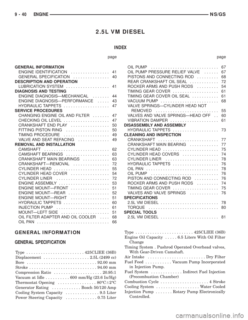
2.5L VM DIESEL
INDEX
page page
GENERAL INFORMATION
ENGINE IDENTIFICATION................ 41
GENERAL SPECIFICATION............... 40
DESCRIPTION AND OPERATION
LUBRICATION SYSTEM.................. 41
DIAGNOSIS AND TESTING
ENGINE DIAGNOSISÐMECHANICAL....... 44
ENGINE DIAGNOSISÐPERFORMANCE..... 43
HYDRAULIC TAPPETS................... 47
SERVICE PROCEDURES
CHANGING ENGINE OIL AND FILTER....... 47
CHECKING OIL LEVEL................... 47
CRANKSHAFT END PLAY................ 50
FITTING PISTON RING.................. 50
TIMING PROCEDURE................... 49
VALVE AND SEAT REFACING............. 49
REMOVAL AND INSTALLATION
CAMSHAFT........................... 62
CAMSHAFT BEARINGS.................. 63
CRANKSHAFT MAIN BEARINGS........... 63
CRANKSHAFTÐREMOVAL............... 72
CYLINDER HEAD....................... 55
CYLINDER HEAD COVER................ 54
CYLINDER LINER...................... 72
ENGINE ASSEMBLY..................... 53
ENGINE MOUNTÐFRONT................ 51
ENGINE MOUNTÐREAR................. 52
ENGINE MOUNTÐRIGHT................ 51
HYDRAULIC TAPPETS................... 60
INJECTION PUMP...................... 61
MOUNTÐLEFT SIDE.................... 51
OIL FILTER ADAPTER AND OIL COOLER.... 68
OILPAN .............................. 66OIL PUMP............................ 67
OIL PUMP PRESSURE RELIEF VALVE...... 67
PISTONS AND CONNECTING ROD......... 68
REAR CRANKSHAFT OIL SEAL............ 72
ROCKER ARMS AND PUSH RODS......... 54
TIMING GEAR COVER................... 61
TIMING GEAR COVER OIL SEAL........... 61
VACUUM PUMP........................ 68
VALVE SPRINGSÐCYLINDER HEAD NOT
REMOVED.......................... 55
VALVES AND VALVE SPRINGSÐHEAD OFF . . 60
VIBRATION DAMPER.................... 61
DISASSEMBLY AND ASSEMBLY
HYDRAULIC TAPPETS................... 73
CLEANING AND INSPECTION
CRANKSHAFT......................... 77
CRANKSHAFT MAIN BEARING............ 77
CYLINDER HEAD....................... 75
CYLINDER HEAD COVERS............... 74
CYLINDER LINER...................... 78
HYDRAULIC TAPPETS................... 76
OILPAN .............................. 78
OIL PUMP............................ 76
PISTON AND CONNECTING ROD.......... 76
ROCKER ARMS AND PUSH RODS......... 74
TIMING GEAR COVER................... 75
VALVES AND VALVE SPRINGS............ 76
SPECIFICATIONS
2.5L VM DIESEL........................ 78
TORQUE............................. 80
SPECIAL TOOLS
2.5L VM DIESEL........................ 81
GENERAL INFORMATION
GENERAL SPECIFICATION
Type ........................425CLIEE (36B)
Displacement...................2.5L (2499 cc)
Bore.............................92.00 mm
Stroke............................94.00 mm
Compression Ratio....................20.95:1
Vacuum at Idle..........600mm/Hg (23.6 In/Hg)
Thermostat Opening................80ÉC62ÉC
Generator Rating............Bosch 50/120 Amp
Cooling System Capacity..............9.5Liter
Power Steering Capacity.............0.75 LiterType ........................425CLIEE (36B)
Engine Oil Capacity.....6.5Liters With Oil Filter
Change
Timing System . Pushrod Operated Overhead valves,
With Gear-Driven Camshaft.
Air Intake........................DryFilter
Fuel Feed...........Vacuum Pump Incorporated
in Injection Pump.
Fuel System.............Indirect Fuel Injection
(Precombustion Chamber)
Combustion Cycle....................4Stroke
Cooling System..................Water Cooled
Injection Pump.......Rotary Pump Electronically
Controlled.
9 - 40 ENGINENS/GS
Page 1221 of 1938
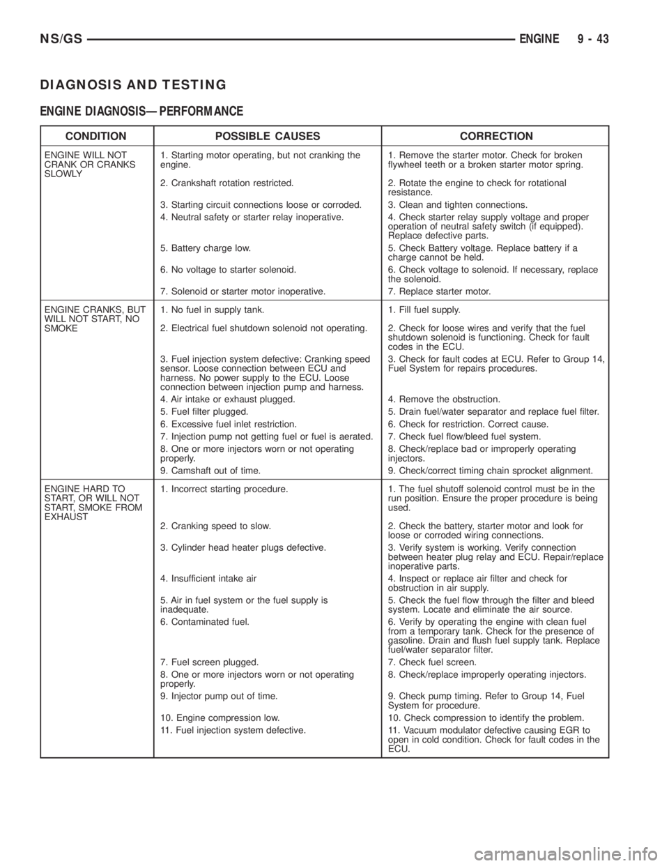
DIAGNOSIS AND TESTING
ENGINE DIAGNOSISÐPERFORMANCE
CONDITION POSSIBLE CAUSES CORRECTION
ENGINE WILL NOT
CRANK OR CRANKS
SLOWLY1. Starting motor operating, but not cranking the
engine.1. Remove the starter motor. Check for broken
flywheel teeth or a broken starter motor spring.
2. Crankshaft rotation restricted. 2. Rotate the engine to check for rotational
resistance.
3. Starting circuit connections loose or corroded. 3. Clean and tighten connections.
4. Neutral safety or starter relay inoperative. 4. Check starter relay supply voltage and proper
operation of neutral safety switch (if equipped).
Replace defective parts.
5. Battery charge low. 5. Check Battery voltage. Replace battery if a
charge cannot be held.
6. No voltage to starter solenoid. 6. Check voltage to solenoid. If necessary, replace
the solenoid.
7. Solenoid or starter motor inoperative. 7. Replace starter motor.
ENGINE CRANKS, BUT
WILL NOT START, NO
SMOKE1. No fuel in supply tank. 1. Fill fuel supply.
2. Electrical fuel shutdown solenoid not operating. 2. Check for loose wires and verify that the fuel
shutdown solenoid is functioning. Check for fault
codes in the ECU.
3. Fuel injection system defective: Cranking speed
sensor. Loose connection between ECU and
harness. No power supply to the ECU. Loose
connection between injection pump and harness.3. Check for fault codes at ECU. Refer to Group 14,
Fuel System for repairs procedures.
4. Air intake or exhaust plugged. 4. Remove the obstruction.
5. Fuel filter plugged. 5. Drain fuel/water separator and replace fuel filter.
6. Excessive fuel inlet restriction. 6. Check for restriction. Correct cause.
7. Injection pump not getting fuel or fuel is aerated. 7. Check fuel flow/bleed fuel system.
8. One or more injectors worn or not operating
properly.8. Check/replace bad or improperly operating
injectors.
9. Camshaft out of time. 9. Check/correct timing chain sprocket alignment.
ENGINE HARD TO
START, OR WILL NOT
START, SMOKE FROM
EXHAUST1. Incorrect starting procedure. 1. The fuel shutoff solenoid control must be in the
run position. Ensure the proper procedure is being
used.
2. Cranking speed to slow. 2. Check the battery, starter motor and look for
loose or corroded wiring connections.
3. Cylinder head heater plugs defective. 3. Verify system is working. Verify connection
between heater plug relay and ECU. Repair/replace
inoperative parts.
4. Insufficient intake air 4. Inspect or replace air filter and check for
obstruction in air supply.
5. Air in fuel system or the fuel supply is
inadequate.5. Check the fuel flow through the filter and bleed
system. Locate and eliminate the air source.
6. Contaminated fuel. 6. Verify by operating the engine with clean fuel
from a temporary tank. Check for the presence of
gasoline. Drain and flush fuel supply tank. Replace
fuel/water separator filter.
7. Fuel screen plugged. 7. Check fuel screen.
8. One or more injectors worn or not operating
properly.8. Check/replace improperly operating injectors.
9. Injector pump out of time. 9. Check pump timing. Refer to Group 14, Fuel
System for procedure.
10. Engine compression low. 10. Check compression to identify the problem.
11. Fuel injection system defective. 11. Vacuum modulator defective causing EGR to
open in cold condition. Check for fault codes in the
ECU.
NS/GSENGINE 9 - 43
Page 1223 of 1938
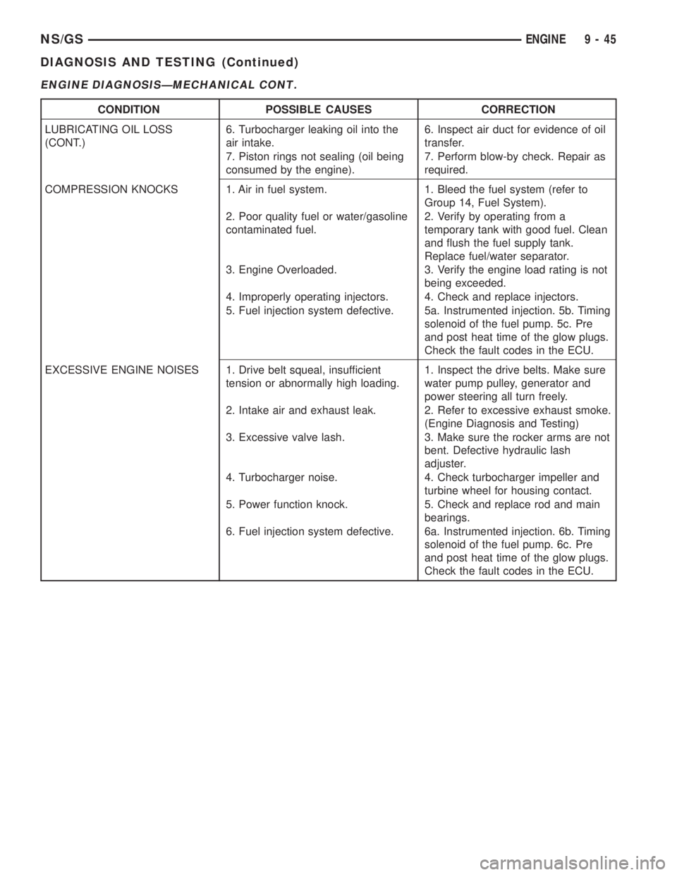
ENGINE DIAGNOSISÐMECHANICAL CONT.
CONDITION POSSIBLE CAUSES CORRECTION
LUBRICATING OIL LOSS
(CONT.)6. Turbocharger leaking oil into the
air intake.6. Inspect air duct for evidence of oil
transfer.
7. Piston rings not sealing (oil being
consumed by the engine).7. Perform blow-by check. Repair as
required.
COMPRESSION KNOCKS 1. Air in fuel system. 1. Bleed the fuel system (refer to
Group 14, Fuel System).
2. Poor quality fuel or water/gasoline
contaminated fuel.2. Verify by operating from a
temporary tank with good fuel. Clean
and flush the fuel supply tank.
Replace fuel/water separator.
3. Engine Overloaded. 3. Verify the engine load rating is not
being exceeded.
4. Improperly operating injectors. 4. Check and replace injectors.
5. Fuel injection system defective. 5a. Instrumented injection. 5b. Timing
solenoid of the fuel pump. 5c. Pre
and post heat time of the glow plugs.
Check the fault codes in the ECU.
EXCESSIVE ENGINE NOISES 1. Drive belt squeal, insufficient
tension or abnormally high loading.1. Inspect the drive belts. Make sure
water pump pulley, generator and
power steering all turn freely.
2. Intake air and exhaust leak. 2. Refer to excessive exhaust smoke.
(Engine Diagnosis and Testing)
3. Excessive valve lash. 3. Make sure the rocker arms are not
bent. Defective hydraulic lash
adjuster.
4. Turbocharger noise. 4. Check turbocharger impeller and
turbine wheel for housing contact.
5. Power function knock. 5. Check and replace rod and main
bearings.
6. Fuel injection system defective. 6a. Instrumented injection. 6b. Timing
solenoid of the fuel pump. 6c. Pre
and post heat time of the glow plugs.
Check the fault codes in the ECU.
NS/GSENGINE 9 - 45
DIAGNOSIS AND TESTING (Continued)
Page 1231 of 1938
ENGINE ASSEMBLY
REMOVAL
(1) Disconnect the battery.
(2) Remove the air cleaner assembly and inlet
hose.
(3) Remove both hoses at intercooler and engine.
(4) Disconnect EGR vacuum hose.
(5) Disconnect brake booster vacuum hose.
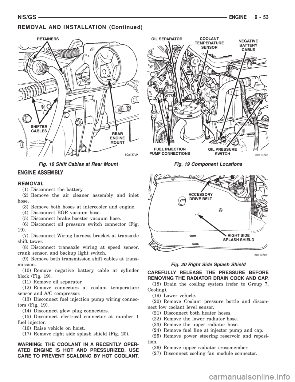
(6) Disconnect oil pressure switch connector (Fig.
19).
(7) Disconnect Wiring harness bracket at transaxle
shift tower.
(8) Disconnect transaxle wiring at speed sensor,
crank sensor, and backup light switch.
(9) Remove both transmission shift cables at trans-
mission.
(10) Remove negative battery cable at cylinder
block (Fig. 19).
(11) Remove oil separator.
(12) Remove connectors at coolant temperature
sensor and A/C compressor.
(13) Disconnect fuel injection pump wiring connec-
tors (Fig. 19).
(14) Disconnect glow plug connectors.
(15) Disconnect electrical connector at number 1
fuel injector.
(16) Raise vehicle on hoist.
(17) Remove right side splash shield (Fig. 20).
WARNING: THE COOLANT IN A RECENTLY OPER-
ATED ENGINE IS HOT AND PRESSURIZED. USE
CARE TO PREVENT SCALDING BY HOT COOLANT.CAREFULLY RELEASE THE PRESSURE BEFORE
REMOVING THE RADIATOR DRAIN COCK AND CAP.
(18) Drain the cooling system (refer to Group 7,
Cooling).
(19) Lower vehicle.
(20) Remove Coolant pressure bottle and discon-
nect low coolant level sensor.
(21) Disconnect both heater hoses.
(22) Remove the lower radiator hose.
(23) Remove the upper radiator hose.
(24) Remove fuel line at injector pump and cap.
(25) Remove power steering reservoir and reposi-
tion.
(26) Remove upper radiator crossmember.
(27) Disconnect cooling fan module connector.
Fig. 18 Shift Cables at Rear MountFig. 19 Component Locations
Fig. 20 Right Side Splash Shield
NS/GSENGINE 9 - 53
REMOVAL AND INSTALLATION (Continued)
Page 1239 of 1938
(3) Install cylinder head, intake manifold, and
exhaust manifold. Refer to cylinder head installation
in this section.
(4) Install push rods in original positions.
(5) Install rocker arms in original positions.
(6) Install cylinder head cover. Refer to cylinder
valve cover installation in this section.
(7) Start and operate engine. Warm up to normal
operating temperature.
CAUTION: To prevent damage to valve mechanism,
engine must not be run above fast idle until all
hydraulic tappets have filled with oil and have
become quiet.
VIBRATION DAMPER
REMOVAL
(1) Disconnect the battery cable.
(2) Raise vehicle on hoist.
(3) Remove right side lower splash shield.
(4) Remove generator, power steering belt. Refer to
Group 7, Cooling.
(5) Remove water pump belt. Refer to Group 7,
Cooling.
(6) Remove engine starter. Refer to Group, 8B for
procedure
(7) Install flywheel locking tool VM.1014 to pre-
vent engine rotation.
NOTE: Crankshaft damper nut is left handed
thread.
(8) Remove vibration damper nut.
(9) Remove vibration damper. No special tool is
needed for removal.
CAUTION: If thread sealant is used it is important
to remove all the old thread sealant from the
threads on the crankshaft.
INSTALLATION
NOTE: Before installing damper be sure the O-ring
inside the center of the damper is in its grove.
(1) Install vibration damper.
CAUTION: Correct torque on the vibration damper
nut is important or engine damage can occur.
(2) Install vibration damper nut and tighten to 441
N´m (325 ft. lbs.).
(3) Remove flywheel locking tool, and install
engine starter.(4) Install both accessary drive belts. Refer to
Group 7, Cooling.
(5) Install right splash shield.
(6) Lower vehicle.
(7) Connect the battery cable.
TIMING GEAR COVER OIL SEAL
REMOVAL
(1) Disconnect the battery cable.
(2) Remove vibration damper. Refer to vibration
damper removal in this section.
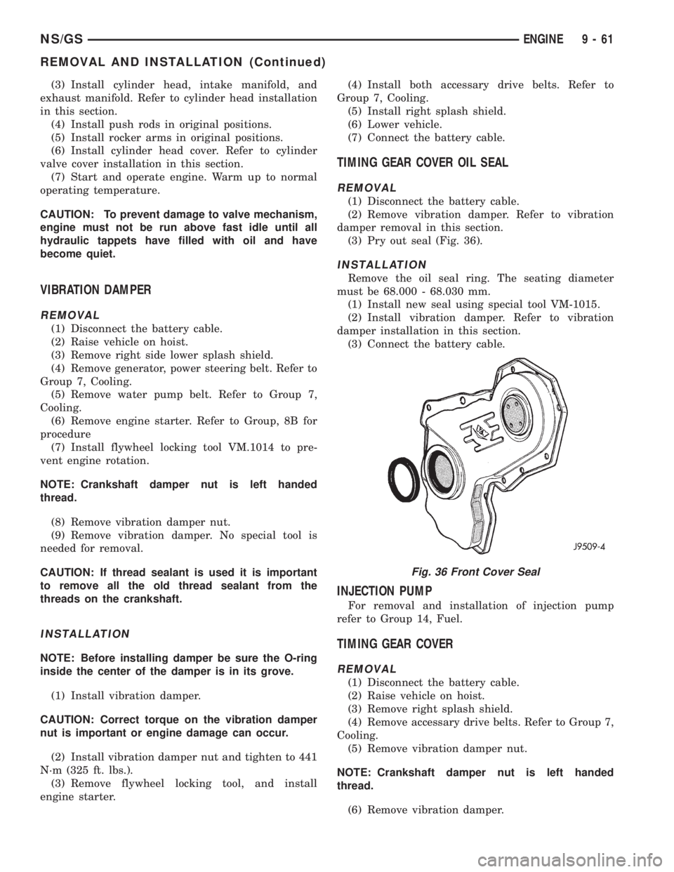
(3) Pry out seal (Fig. 36).
INSTALLATION
Remove the oil seal ring. The seating diameter
must be 68.000 - 68.030 mm.
(1) Install new seal using special tool VM-1015.
(2) Install vibration damper. Refer to vibration
damper installation in this section.
(3) Connect the battery cable.
INJECTION PUMP
For removal and installation of injection pump
refer to Group 14, Fuel.
TIMING GEAR COVER
REMOVAL
(1) Disconnect the battery cable.
(2) Raise vehicle on hoist.
(3) Remove right splash shield.
(4) Remove accessary drive belts. Refer to Group 7,
Cooling.
(5) Remove vibration damper nut.
NOTE: Crankshaft damper nut is left handed
thread.
(6) Remove vibration damper.
Fig. 36 Front Cover Seal
NS/GSENGINE 9 - 61
REMOVAL AND INSTALLATION (Continued)
Page 1323 of 1938
FUEL INJECTION SYSTEM
INDEX
page page
GENERAL INFORMATION
INTRODUCTION......................... 30
MODES OF OPERATION.................. 30
DESCRIPTION AND OPERATION
AIR CONDITIONING (A/C) CLUTCH RELAYÐ
PCM OUTPUT......................... 41
AIR CONDITIONING PRESSURE
TRANSDUCERÐPCM INPUT............. 33
AIR CONDITIONING SWITCH SENSEÐ
PCM INPUT........................... 33
AUTOMATIC SHUTDOWN (ASD) SENSEÐ
PCM INPUT........................... 33
AUTOMATIC SHUTDOWN RELAYÐPCM
OUTPUT............................. 42
AUTOMATIC TRANSAXLE CONTROL
MODULEÐPCM OUTPUT................ 44
BATTERY VOLTAGEÐPCM INPUT........... 33
BRAKE SWITCHÐPCM INPUT.............. 33
CAMSHAFT POSITION SENSORÐPCM INPUT . 33
CCDBUS .............................. 32
CRANKSHAFT POSITION SENSORÐPCM
INPUT............................... 35
DATA LINK CONNECTORÐPCM OUTPUT..... 44
DUTY CYCLE EVAP CANISTER PURGE
SOLENOIDÐPCM OUTPUT.............. 43
ELECTRONIC EGR TRANSDUCER
SOLENOIDÐPCM OUTPUT.............. 43
ENGINE COOLANT TEMPERATURE SENSORÐ
PCM INPUT........................... 36
FUEL INJECTORSÐPCM OUTPUT.......... 44
FUEL PUMP RELAYÐPCM OUTPUT......... 42
GENERATOR FIELDÐPCM OUTPUT......... 42
HEATED OXYGEN SENSOR (O2S SENSOR)Ð
PCM INPUT........................... 37
IDLE AIR CONTROL MOTORÐPCM OUTPUT . . 42
IGNITION COILÐPCM OUTPUT............. 45
INTAKE AIR TEMPERATURE SENSORÐPCM
INPUT (2.4L ONLY)..................... 41
KNOCK SENSORÐPCM INPUT............. 38
MALFUNCTION INDICATOR (CHECK ENGINE)
LAMPÐPCM OUTPUT.................. 46
MANIFOLD ABSOLUTE PRESSURE (MAP)
SENSORÐPCM INPUT.................. 39
POWERTRAIN CONTROL MODULE (PCM).... 32
PROPORTIONAL PURGE SOLENOID......... 43
SOLID STATE FAN RELAYÐPCM OUTPUT.... 46
SPEED CONTROL SOLENOIDSÐ
PCM OUTPUT......................... 46
SPEED CONTROLÐPCM INPUT............ 39STARTER RELAYÐPCM OUTPUT........... 42
SYSTEM DIAGNOSIS..................... 32
TACHOMETERÐPCM OUTPUT............. 47
THROTTLE BODY....................... 47
THROTTLE POSITION SENSOR (TPS)Ð
PCM INPUT........................... 40
TORQUE CONVERTER CLUTCH SOLENOIDÐ
PCM OUTPUT......................... 46
TRANSAXLE PARK/NEUTRAL SWITCHÐ
PCM INPUT........................... 40
VEHICLE SPEED AND DISTANCEÐ
PCM INPUT........................... 41
DIAGNOSIS AND TESTING
ASD AND FUEL PUMP RELAYS............. 59
CAMSHAFT AND CRANKSHAFT POSITION
SENSOR............................. 61
ENGINE COOLANT TEMPERATURE SENSOR . . 61
HEATED OXYGEN SENSOR............... 61
KNOCK SENSOR........................ 61
MANIFOLD ABSOLUTE PRESSURE (MAP)
SENSOR............................. 60
THROTTLE BODY MINIMUM AIR FLOW
CHECK PROCEDURE................... 62
THROTTLE POSITION SENSOR............ 62
VISUAL INSPECTIONÐ2.4L ENGINE......... 47
VISUAL INSPECTIONÐ3.0L ENGINE......... 52
VISUAL INSPECTIONÐ3.3/3.8L ENGINES..... 55
REMOVAL AND INSTALLATION
AIR CLEANER ELEMENT.................. 70
AUTOMATIC SHUTDOWN (ASD) RELAY...... 64
CAMSHAFT POSITION SENSOR............ 68
CRANKSHAFT POSITION SENSOR.......... 68
DOWNSTREAM OXYGEN SENSOR.......... 69
ENGINE COOLANT TEMPERATURE
SENSORÐ2.4L........................ 70
ENGINE COOLANT TEMPERATURE
SENSORÐ3.0L........................ 71
ENGINE COOLANT TEMPERATURE
SENSORÐ3.3/3.8L..................... 71
FUEL PUMP RELAY...................... 64
IDLE AIR CONTROL MOTOR............... 65
INTAKE AIR TEMPERATURE SENSORÐ2.4L . . . 72
KNOCK SENSOR........................ 70
MANIFOLD ABSOLUTE PRESSURE (MAP)
SENSORÐ2.4/3.3/3.8L.................. 66
MANIFOLD ABSOLUTE PRESSURE (MAP)
SENSORÐ3.0L........................ 66
POWERTRAIN CONTROL MODULE.......... 67
PROPORTIONAL PURGE SOLENOID VALVE . . . 66
NSFUEL SYSTEM 14 - 29
Page 1324 of 1938
THROTTLE BODY....................... 64
THROTTLE POSITION SENSOR............ 65
UPSTREAM OXYGEN SENSOR............. 68
SPECIFICATIONS
TORQUE.............................. 72SPECIAL TOOLS
FUEL................................. 72
GENERAL INFORMATION
INTRODUCTION
All engines used in this section have a sequential
Multi-Port Electronic Fuel Injection system. The MPI
system is computer regulated and provides precise
air/fuel ratios for all driving conditions. The Power-
train Control Module (PCM) operates the fuel injec-
tion system.
The PCM regulates:
²Ignition timing
²Air/fuel ratio
²Emission control devices
²Cooling fan
²Charging system
²Idle speed
²Vehicle speed control
Various sensors provide the inputs necessary for
the PCM to correctly operate these systems. In addi-
tion to the sensors, various switches also provide
inputs to the PCM.
All inputs to the PCM are converted into signals.
The PCM can adapt its programming to meet chang-
ing operating conditions.
Fuel is injected into the intake port above the
intake valve in precise metered amounts through
electrically operated injectors. The PCM fires the
injectors in a specific sequence. Under most operat-
ing conditions, the PCM maintains an air fuel ratio
of 14.7 parts air to 1 part fuel by constantly adjust-
ing injector pulse width. Injector pulse width is the
length of time the injector is open.
The PCM adjusts injector pulse width by opening
and closing the ground path to the injector. Engine
RPM (speed) and manifold absolute pressure (air
density) are the primary inputs that determine injec-
tor pulse width.
MODES OF OPERATION
As input signals to the PCM change, the PCM
adjusts its response to output devices. For example,
the PCM must calculate a different injector pulse
width and ignition timing for idle than it does for
Wide Open Throttle (WOT). There are several differ-
ent modes of operation that determine how the PCM
responds to the various input signals.
There are two different areas of operation, OPEN
LOOP and CLOSED LOOP.
During OPEN LOOP modes the PCM receives
input signals and responds according to preset PCMprogramming. Input from the oxygen (O2S) sensor is
not monitored during OPEN LOOP modes.
During CLOSED LOOP modes the PCM does mon-
itor the O2S sensor input. This input indicates to the
PCM whether or not the calculated injector pulse
width results in the ideal air/fuel ratio of 14.7 parts
air to 1 part fuel. By monitoring the exhaust oxygen
content through the O2S sensor, the PCM can fine
tune the injector pulse width. Fine tuning injector
pulse width allows the PCM to achieve optimum fuel
economy combined with low emissions.
The multi-port fuel injection system has the follow-
ing modes of operation:
²Ignition switch ON (zero RPM)
²Engine start-up
²Engine warm-up
²Cruise (Idle)
²Acceleration
²Deceleration
²Wide Open Throttle
²Ignition switch OFF
The engine start-up (crank), engine warm-up, and
wide open throttle modes are OPEN LOOP modes.
Under most operating conditions, the acceleration,
deceleration, and cruise modes,with the engine at
operating temperatureare CLOSED LOOP modes.
IGNITION SWITCH ON (ZERO RPM) MODE
When the multi-port fuel injection system is acti-
vated by the ignition switch, the following actions
occur:
²The PCM determines atmospheric air pressure
from the MAP sensor input to determine basic fuel
strategy.
²The PCM monitors the coolant temperature sen-
sor and throttle position sensor input. The PCM mod-
ifies fuel strategy based on this input.
When the key is in the ON position and the engine
is not running (zero rpm), the Automatic Shutdown
(ASD) relay and fuel pump relay are not energized.
Therefore battery voltage is not supplied to the fuel
pump, ignition coil, fuel injectors or oxygen sensor
heating element.
ENGINE START-UP MODE
This is an OPEN LOOP mode. The following
actions occur when the starter motor is engaged.
If the PCM receives the camshaft position sensor
and crankshaft position sensor signals, it energizes
the ASD relay and fuel pump relay. These relays sup-
ply battery voltage to the fuel pump, fuel injectors,
14 - 30 FUEL SYSTEMNS
SPECIFICATIONS (Continued)