lug pattern CHRYSLER VOYAGER 1996 Service Manual
[x] Cancel search | Manufacturer: CHRYSLER, Model Year: 1996, Model line: VOYAGER, Model: CHRYSLER VOYAGER 1996Pages: 1938, PDF Size: 55.84 MB
Page 193 of 1938
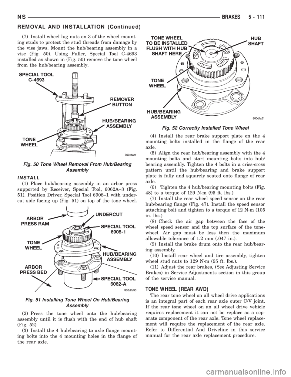
(7) Install wheel lug nuts on 3 of the wheel mount-
ing studs to protect the stud threads from damage by
the vise jaws. Mount the hub/bearing assembly in a
vise (Fig. 50). Using Puller, Special Tool C-4693
installed as shown in (Fig. 50) remove the tone wheel
from the hub/bearing assembly.
INSTALL
(1) Place hub/bearing assembly in an arbor press
supported by Receiver, Special Tool, 6062A±3 (Fig.
51). Position Driver, Special Tool 6908±1 with under-
cut side facing up (Fig. 51) on top of the tone wheel.
(2) Press the tone wheel onto the hub/bearing
assembly until it is flush with the end of hub shaft
(Fig. 52).
(3) Install the 4 hub/bearing to axle flange mount-
ing bolts into the 4 mounting holes in the flange of
the rear axle.(4) Install the rear brake support plate on the 4
mounting bolts installed in the flange of the rear
axle.
(5) Align the rear hub/bearing assembly with the 4
mounting bolts and start mounting bolts into hub/
bearing assembly. Tighten the 4 bolts in a criss-cross
pattern until the hub/bearing and brake support
plate is fully and squarely seated onto flange of rear
axle.
(6) Tighten the 4 hub/bearing mounting bolts (Fig.
48) to a torque of 129 N´m (95 ft. lbs.)
(7) Install the rear wheel speed sensor on the rear
hub/bearing flange (Fig. 47). Install the speed sensor
attaching bolt and tighten to a torque of 12 N´m (105
in. lbs.).
(8) Check the air gap between the face of the
wheel speed sensor and the top surface of the tone-
wheel. Air gap must be less then the maximum
allowable tolerance of 1.2 mm (.047 in.).
(9) Install the brake drum onto the rear hub/bear-
ing assembly.
(10) Install rear wheel and tire assembly, tighten
wheel stud nuts to 129 N´m (95 ft. lbs.).
(11) Adjust the rear brakes, (See Adjusting Service
Brakes) in Service Adjustments section in this group
of the service manual.
TONE WHEEL (REAR AWD)
The rear tone wheel on all wheel drive applications
is an integral part of each rear axle outer C/V joint.
If the rear tone wheel on an all wheel drive vehicle
requires replacement it can not be replace as a sep-
arate component of the rear axle. Tone wheel replace-
ment will require the replacement of the rear axle.
Refer to Differential And Driveline in this service
manual for the rear axle replacement procedure.
Fig. 50 Tone Wheel Removal From Hub/Bearing
Assembly
Fig. 51 Installing Tone Wheel On Hub/Bearing
Assembly
Fig. 52 Correctly Installed Tone Wheel
NSBRAKES 5 - 111
REMOVAL AND INSTALLATION (Continued)
Page 309 of 1938
either the crankshaft position sensor/camshaft posi-
tion sensor 8 volt supply circuit, or the camshaft
position sensor output or ground circuits. Use the
DRB scan tool to test the camshaft position sensor
and the sensor circuits. Refer to the appropriate Pow-
ertrain Diagnostics Procedure Manual. Refer to the
wiring diagrams section for circuit information.
IGNITION TIMING PROCEDURE
The engines for this vehicle, use a fixed ignition
system. The PCM regulates ignition timing. Basic
ignition timing is not adjustable.
MANIFOLD ABSOLUTE PRESSURE (MAP) SENSOR
TEST
Refer to Group 14, Fuel System for Diagnosis and
Testing.
CAMSHAFT POSITION SENSOR AND CRANKSHAFT
POSITION SENSOR
The output voltage of a properly operating cam-
shaft position sensor or crankshaft position sensor
switches from high (5.0 volts) to low (0.3 volts). By
connecting an Moper Diagonostic System (MDS) and
engine analyzer to the vehicle, technicians can view
the square wave pattern.
ENGINE COOLANT TEMPERATURE SENSOR
Refer to Group 14, Fuel System for Diagnosis and
Testing.
INTAKE AIR TEMPERATURE SENSOR
Refer to Group 14, Fuel System, for Diagnosis and
Testing.
SPARK PLUG CONDITION
NORMAL OPERATING CONDITIONS
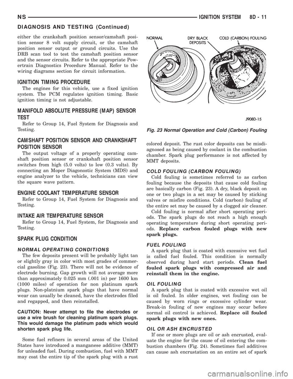
The few deposits present will be probably light tan
or slightly gray in color with most grades of commer-
cial gasoline (Fig. 23). There will not be evidence of
electrode burning. Gap growth will not average more
than approximately 0.025 mm (.001 in) per 1600 km
(1000 miles) of operation for non platinum spark
plugs. Non-platnium spark plugs that have normal
wear can usually be cleaned, have the electrodes filed
and regapped, and then reinstalled.
CAUTION: Never attempt to file the electrodes or
use a wire brush for cleaning platinum spark plugs.
This would damage the platinum pads which would
shorten spark plug life.
Some fuel refiners in several areas of the United
States have introduced a manganese additive (MMT)
for unleaded fuel. During combustion, fuel with MMT
may coat the entire tip of the spark plug with a rustcolored deposit. The rust color deposits can be misdi-
agnosed as being caused by coolant in the combustion
chamber. Spark plug performance is not affected by
MMT deposits.
COLD FOULING (CARBON FOULING)
Cold fouling is sometimes referred to as carbon
fouling because the deposits that cause cold fouling
are basically carbon (Fig. 23). A dry, black deposit on
one or two plugs in a set may be caused by sticking
valves or misfire conditions. Cold (carbon) fouling of
the entire set may be caused by a clogged air cleaner.
Cold fouling is normal after short operating peri-
ods. The spark plugs do not reach a high enough
operating temperature during short operating peri-
ods.Replace carbon fouled plugs with new
spark plugs.
FUEL FOULING
A spark plug that is coated with excessive wet fuel
is called fuel fouled. This condition is normally
observed during hard start periods.Clean fuel
fouled spark plugs with compressed air and
reinstall them in the engine.
OIL FOULING
A spark plug that is coated with excessive wet oil
is oil fouled. In older engines, wet fouling can be
caused by worn rings or excessive cylinder wear.
Break-in fouling of new engines may occur before
normal oil control is achieved.Replace oil fouled
spark plugs with new ones.
OIL OR ASH ENCRUSTED
If one or more plugs are oil or ash encrusted, eval-
uate the engine for the cause of oil entering the com-
bustion chambers (Fig. 24). Sometimes fuel additives
can cause ash encrustation on an entire set of spark
Fig. 23 Normal Operation and Cold (Carbon) Fouling
NSIGNITION SYSTEM 8D - 11
DIAGNOSIS AND TESTING (Continued)
Page 314 of 1938
2.4L ENGINE
INDEX
page page
DESCRIPTION AND OPERATION
CAMSHAFT POSITION SENSOR............ 17
CRANKSHAFT POSITION SENSOR.......... 16
FIRING ORDERÐ2.4L.................... 16
INTAKE AIR TEMPERATURE SENSORÐ2.4L . . . 17
REMOVAL AND INSTALLATION
CAMSHAFT POSITION SENSOR............ 19
CRANKSHAFT POSITION SENSOR.......... 19
ENGINE COOLANT TEMPERATURE SENSORÐ
2.4L................................. 20
IGNITION COILÐ2.4L..................... 18
INTAKE AIR TEMPERATURE SENSORÐ2.4L . . . 21KNOCK SENSORÐ2.4L................... 21
MANIFOLD ABSOLUTE PRESSURE (MAP)
SENSORÐ2.4/3.3/3.8L.................. 20
SPARK PLUG CABLE SERVICEÐ2.4L........ 18
SPARK PLUG SERVICE................... 18
THROTTLE POSITION SENSOR............ 20
SPECIFICATIONS
IGNITION COIL......................... 22
SPARK PLUG CABLE RESISTANCEÐ2.4L..... 22
SPARK PLUG........................... 22
TORQUE.............................. 22
DESCRIPTION AND OPERATION
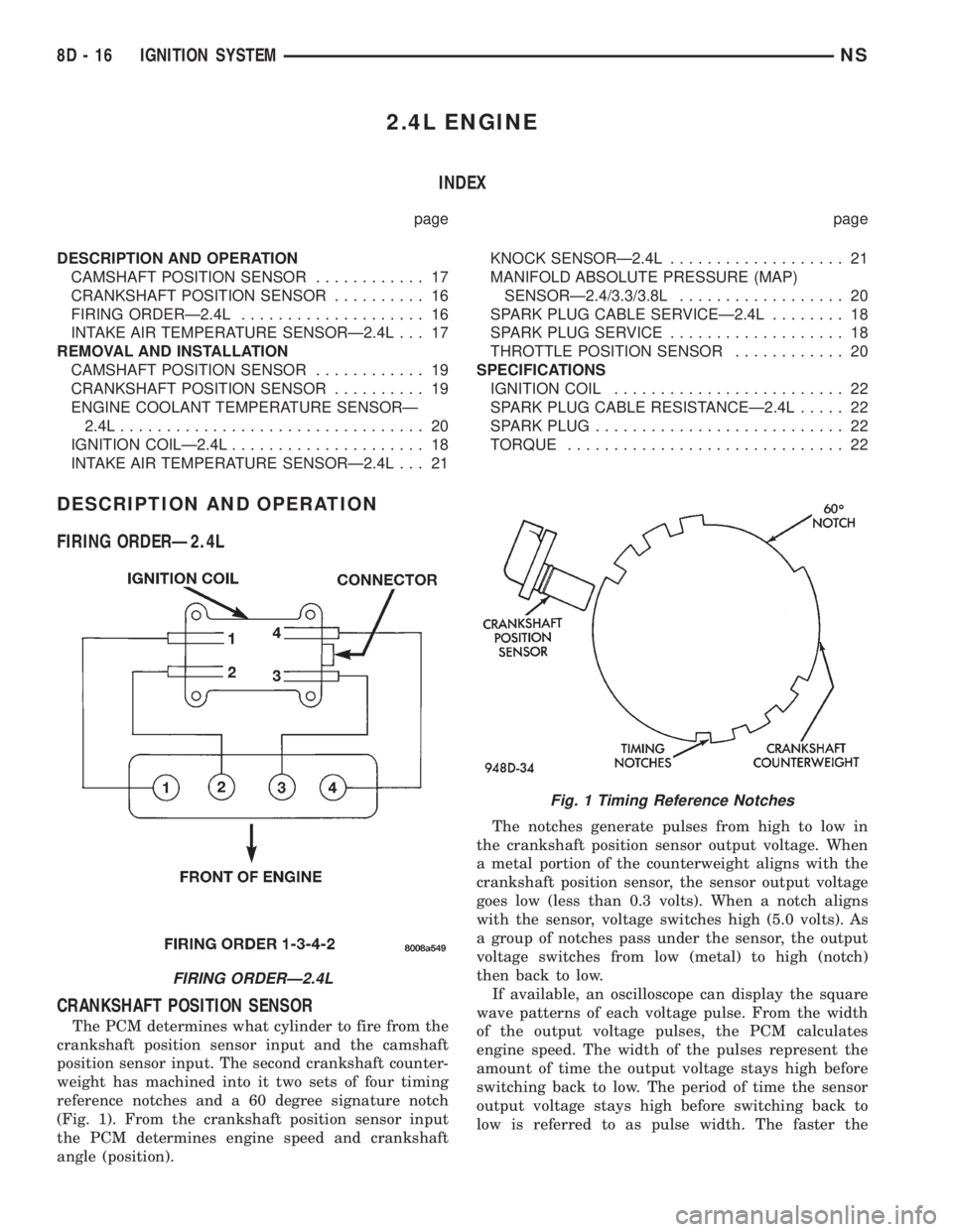
FIRING ORDERÐ2.4L
CRANKSHAFT POSITION SENSOR
The PCM determines what cylinder to fire from the
crankshaft position sensor input and the camshaft
position sensor input. The second crankshaft counter-
weight has machined into it two sets of four timing
reference notches and a 60 degree signature notch
(Fig. 1). From the crankshaft position sensor input
the PCM determines engine speed and crankshaft
angle (position).The notches generate pulses from high to low in
the crankshaft position sensor output voltage. When
a metal portion of the counterweight aligns with the
crankshaft position sensor, the sensor output voltage
goes low (less than 0.3 volts). When a notch aligns
with the sensor, voltage switches high (5.0 volts). As
a group of notches pass under the sensor, the output
voltage switches from low (metal) to high (notch)
then back to low.
If available, an oscilloscope can display the square
wave patterns of each voltage pulse. From the width
of the output voltage pulses, the PCM calculates
engine speed. The width of the pulses represent the
amount of time the output voltage stays high before
switching back to low. The period of time the sensor
output voltage stays high before switching back to
low is referred to as pulse width. The faster the
FIRING ORDERÐ2.4L
Fig. 1 Timing Reference Notches
8D - 16 IGNITION SYSTEMNS
Page 1053 of 1938
(5) Test resistance of spark plug cables. Refer to
Group 8D, Ignition System.
(6) Test ignition coils primary and secondary resis-
tance. Replace parts as necessary. Refer to Group 8D,
Ignition System.
(7) Check fuel pump pressure at idle and different
RPM ranges. Refer to Group 14, Fuel System for
Specifications.
(8) The air filter elements should be replaced as
specified in Group 0, Lubrication and Maintenance.
(9) Inspect crankcase ventilation system as out-
lined in Group 25, Emission Control Systems.
(10) Road test vehicle as a final test.
HONING CYLINDER BORES
(1) Used carefully, the cylinder bore resizing hone
C-823 equipped with 220 grit stones, is the best tool
for this job. In addition to deglazing, it will reduce
taper and out-of-round as well as removing light
scuffing, scoring or scratches. Usually a few strokes
will clean up a bore and maintain the required lim-
its.
(2) Deglazing of the cylinder walls may be done
using a cylinder surfacing hone, Tool C-3501,
equipped with 280 grit stones, if the cylinder bore is
straight and round. 20-60 strokes depending on the
bore condition, will be sufficient to provide a satisfac-
tory surface. Inspect cylinder walls after each 20
strokes, using a light honing oil.Do not use engine
or transmission oil, mineral spirits or kerosene.
(3) Honing should be done by moving the hone up
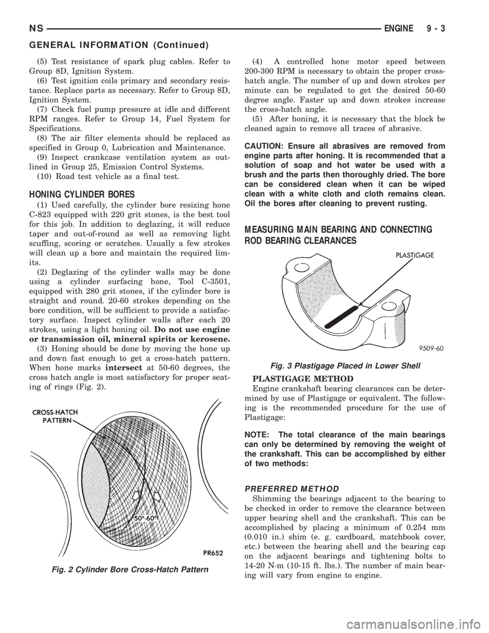
and down fast enough to get a cross-hatch pattern.
When hone marksintersectat 50-60 degrees, the
cross hatch angle is most satisfactory for proper seat-
ing of rings (Fig. 2).(4) A controlled hone motor speed between
200-300 RPM is necessary to obtain the proper cross-
hatch angle. The number of up and down strokes per
minute can be regulated to get the desired 50-60
degree angle. Faster up and down strokes increase
the cross-hatch angle.
(5) After honing, it is necessary that the block be
cleaned again to remove all traces of abrasive.
CAUTION: Ensure all abrasives are removed from
engine parts after honing. It is recommended that a
solution of soap and hot water be used with a
brush and the parts then thoroughly dried. The bore
can be considered clean when it can be wiped
clean with a white cloth and cloth remains clean.
Oil the bores after cleaning to prevent rusting.
MEASURING MAIN BEARING AND CONNECTING
ROD BEARING CLEARANCES
PLASTIGAGE METHOD
Engine crankshaft bearing clearances can be deter-
mined by use of Plastigage or equivalent. The follow-
ing is the recommended procedure for the use of
Plastigage:
NOTE: The total clearance of the main bearings
can only be determined by removing the weight of
the crankshaft. This can be accomplished by either
of two methods:
PREFERRED METHOD
Shimming the bearings adjacent to the bearing to
be checked in order to remove the clearance between
upper bearing shell and the crankshaft. This can be
accomplished by placing a minimum of 0.254 mm
(0.010 in.) shim (e. g. cardboard, matchbook cover,
etc.) between the bearing shell and the bearing cap
on the adjacent bearings and tightening bolts to
14-20 N´m (10-15 ft. lbs.). The number of main bear-
ing will vary from engine to engine.
Fig. 2 Cylinder Bore Cross-Hatch Pattern
Fig. 3 Plastigage Placed in Lower Shell
NSENGINE 9 - 3
GENERAL INFORMATION (Continued)
Page 1059 of 1938
(2) Add an oil soluble dye (use as recommended by
manufacturer). Start the engine and let idle for
approximately 15 minutes. Check the oil dipstick to
make sure the dye is thoroughly mixed as indicated
with a bright yellow color under a black light.
(3) Using a black light, inspect the entire engine
for fluorescent dye, particularly at the suspected area
of oil leak. If the oil leak is found and identified,
repair per service manual instructions.
(4) If dye is not observed, drive the vehicle at var-
ious speeds for approximately 24km (15 miles), and
repeat inspection.
(5)If the oil leak source is not positively
identified at this time, proceed with the air leak
detection test method as follows:
(6) Disconnect the fresh air hose (makeup air) at
the cylinder head cover and plug or cap the nipple on
the cover.
(7) Remove the PCV valve hose from the cylinder
head cover. Cap or plug the PCV valve nipple on the
cover.
(8) Attach an air hose with pressure gauge and
regulator to the dipstick tube.
CAUTION: Do not subject the engine assembly to
more than 20.6 kpa (3 PSI) of test pressure.
(9) Gradually apply air pressure from 1 psi to 2.5
psi maximum while applying soapy water at the sus-
pected source. Adjust the regulator to the suitable
test pressure that provide the best bubbles which
will pinpoint the leak source. If the oil leak is
detected and identified, repair per service manual
procedures.
(10) If the leakage occurs at the rear oil seal area,
refer to the section, Inspection for Rear Seal Area
Leak.
(11) If no leaks are detected, turn off the air sup-
ply and remove the air hose and all plugs and caps.
Install the PCV valve and breather cap hose. Proceed
to next step.
(12) Clean the oil off the suspect oil leak area
using a suitable solvent. Drive the vehicle at various
speeds approximately 24 km (15 miles). Inspect the
engine for signs of an oil leak by using a black light.INSPECTION FOR REAR SEAL AREA LEAKS
Since it is sometimes difficult to determine the
source of an oil leak in the rear seal area of the
engine, a more involved inspection is necessary. The
following steps should be followed to help pinpoint
the source of the leak.
If the leakage occurs at the crankshaft rear oil seal
area:
(1) Disconnect the battery.
(2) Raise the vehicle.
(3) Remove torque converter or clutch housing
cover and inspect rear of block for evidence of oil.
Use a black light to check for the oil leak. If a leak is
present in this area remove transmission for further
inspection.
(a) Circular spray pattern generally indicates
seal leakage or crankshaft damage.
(b) Where leakage tends to run straight down,
possible causes are a porous block, oil galley cup
plug, bedplate to cylinder block mating surfaces
and seal bore. See proper repair procedures for
these items.
(4) If no leaks are detected, pressurized the crank-
case as outlined in the, Inspection (Engine oil Leaks
in general)
CAUTION: Do not exceed 20.6 kPa (3 psi).
(5) If the leak is not detected, very slowly turn the
crankshaft and watch for leakage. If a leak is
detected between the crankshaft and seal while
slowly turning the crankshaft, it is possible the
crankshaft seal surface is damaged. The seal area on
the crankshaft could have minor nicks or scratches
that can be polished out with emery cloth.
CAUTION: Use extreme caution when crankshaft
polishing is necessary to remove minor nicks and
scratches. The crankshaft seal flange is especially
machined to complement the function of the rear oil
seal.
(6) For bubbles that remain steady with shaft
rotation, no further inspection can be done until dis-
assembled.
(7) After the oil leak root cause and appropriate
corrective action have been identified. Refer to Rear
Crankshaft Seals, for proper replacement procedures.
NSENGINE 9 - 9
DIAGNOSIS AND TESTING (Continued)
Page 1675 of 1938
(22) Remove lower starter bolt.
(23) Remove engine wiring harness clip.
CAUTION: Always use a safety chain when remov-
ing or installing transaxle assembly.
(24) Place a transmission jack under the transmis-
sion
(25) Remove the transaxle lower dust cover.
(26) Remove the access cover in right splash shield
to access torsional damper bolt.
(27) Remove drive plate to modular clutch bolts
while holding torsional damper bolt with socket and
ratchet. To avoid distortion of the drive plate, remove
the modular clutch bolts a few turns at a time. Use a
crisscross pattern until all bolts are loosened.
(28) Unbolt rear engine mount through bolt and
two (2) mount bolts.
(29) Remove the left front fender splash shield.
(30) Unbolt left engine mount through bolt and
unbolt mount from the transaxle.(31) Remove front engine mount (Fig. 60) and (Fig.
61).
(32) Lower the transaxle and modular clutch.
To service the drive plate, refer to Group 9, Engine.
INSTALLATION
(1) Position the modular clutch assembly onto the
input shaft of the transaxle (Fig. 62).
(2) To reinstall transaxle, reverse removal proce-
dure making certain to align the elongated hole in
the drive plate with the modular clutch bolt hole that
has the white paint mark.
Fig. 57 Unseat Control Arm
Fig. 58 Transaxle Drain Plug
Fig. 59 Vehicle Speed Sensor
Fig. 60 Front Engine Mount (Left Side)
NS/GSA±598 MANUAL TRANSAXLE 21 - 19
REMOVAL AND INSTALLATION (Continued)