engine vacuum CHRYSLER VOYAGER 2000 Diagnostic Manual
[x] Cancel search | Manufacturer: CHRYSLER, Model Year: 2000, Model line: VOYAGER, Model: CHRYSLER VOYAGER 2000Pages: 364, PDF Size: 2.17 MB
Page 237 of 364

Symptom:
* CHECKING ENGINE VACUUM
TEST ACTION APPLICABILITY
1 Ignition Off
Connect a Vacuum Gauge to a Vacuum Source on the Engine.
Start the Engine and allow it to idle.
Note: The normal vacuum reading will vary according to the altitude.
While monitoring the vacuum gauge, snap the throttle open a few times. Refer to
vacuum gauge specifications in support material.
Observe the Vacuum Gauge reading at idle.
Is the Vacuum Gauge reading between 13 inches and 22 inches steady?All
Ye s®Test Complete.
No®Refer to symptom * CHECKING THE ENGINE MECHANICAL
SYSTEMS in the DRIVEABILITY category.
231
DRIVEABILITY
ProCarManuals.com
Page 238 of 364

Symptom:
* CHECKING EVAPORATIVE EMISSION SYSTEM
POSSIBLE CAUSES
EVAP PURGE SOLENOID DEFECTIVE
EVAP PURGE SOLENOID DEFECTIVE
EVAPORATIVE CANISTER DEFECTIVE
EVAPORATIVE EMISSION VACUUM HOSE OBSERVABLE DEFECT
VACUUM LINE OBSERVABLE DEFECT
VACUUM LINE PLUGGED
VACUUM LINE PLUGGED
TEST PASSED
TEST ACTION APPLICABILITY
1 Ignition Off
Note: Carefully inspect all Vacuum Hoses for proper routing and for
pinched or plugged Hoses from the engine to the PPS to the Gas Tank.
Are all the Vacuum Hoses OK?All
Ye s®Go To 2
No®Repair the Vacuum Hoses as necessary.
Perform Powertrain Verification Test VER-2A.
2 Ignition Off
Start the engine and allow it to reach normal operating temperature 76 deg C (170
deg. F).
Turn ignition off.
Disconnect the Purge Vacuum Hose at the Solenoid that goes to the Canister.
Start the engine.
Note: There should be no flow through the Solenoid from 1 to 2 minutes.
Is the PPS allowing vacuum through the Solenoid within 1 minute?All
Ye s®Go To 3
No®Go To 6
3 Ignition Off
Inspect the line from the PPS to the Canister.
Is the line disconnected, ripped or cut?All
Ye s®Repair the Line and replace the Purge Solenoid.
Perform Powertrain Verification Test VER-2A.
No®Go To 4
4 Ignition Off
Remove the Purge Solenoid and tap the ports against a clean solid surface.
Did any foreign material fall out?All
Ye s®Go To 5
No®Replace the Evap Purge Solenoid.
Perform Powertrain Verification Test VER-6A.
232
DRIVEABILITY
ProCarManuals.com
Page 239 of 364

TEST ACTION APPLICABILITY
5 If there are no potential causes remaining, the Vacuum Line is assumed to be
defective.
View repair options.All
Repair
Clean out the Line and replace the PPS and Canister.
Perform Powertrain Verification Test VER-2A.
6 Ignition Off
Disconnect the Purge Vacuum Hose at the Solenoid that goes to the Canister.
Note: In the next steps, do not use more that five PSI.
Attempt to blow air through the Vacuum Line that goes to the canister.
Does the Canister and Vacuum Line allow air to pass?All
Ye s®Purge Solenoid and hoses OK. Test passed.
No®Go To 7
7 Ignition Off
Start the engine and allow it to reach normal operating temperature 76 deg C (170
deg F).
Turn ignition off.
Disconnect the Purge Vacuum Hose at the Solenoid that goes to the Canister.
Start the engine.
Note: After 90 seconds, the Purge Solenoid will allow vacuum to cycle
intermittently at a steady rate.
Is the Evap Solenoid allowing vacuum to cycle through intermittently at a steady
rate?All
Ye s®Go To 8
No®Replace the Purge Solenoid.
Perform Powertrain Verification Test VER-6A.
8 Ignition Off
Note: In the next steps, do not use more than five psi.
Disconnect the Purge Vacuum Hose at the Solenoid that goes to the Canister.
Disconnect the Vacuum Line at the Canister that goes to the EVAP Solenoid.
Attempt to blow air through the Vacuum Line that goes to the Canister.
Does the Vacuum Line allow air to pass?All
Ye s®Go To 9
No®Repair or replace the Vacuum Line.
Perform Powertrain Verification Test VER-2A.
9 If there are no potential causes remaining, the Evaporative Canister is assumed to be
defective.
View repair options.All
Repair
Replace the Evaporative Canister.
Perform Powertrain Verification Test VER-2A.
233
DRIVEABILITY
* CHECKING EVAPORATIVE EMISSION SYSTEM ÐContinued
ProCarManuals.com
Page 240 of 364
Symptom:
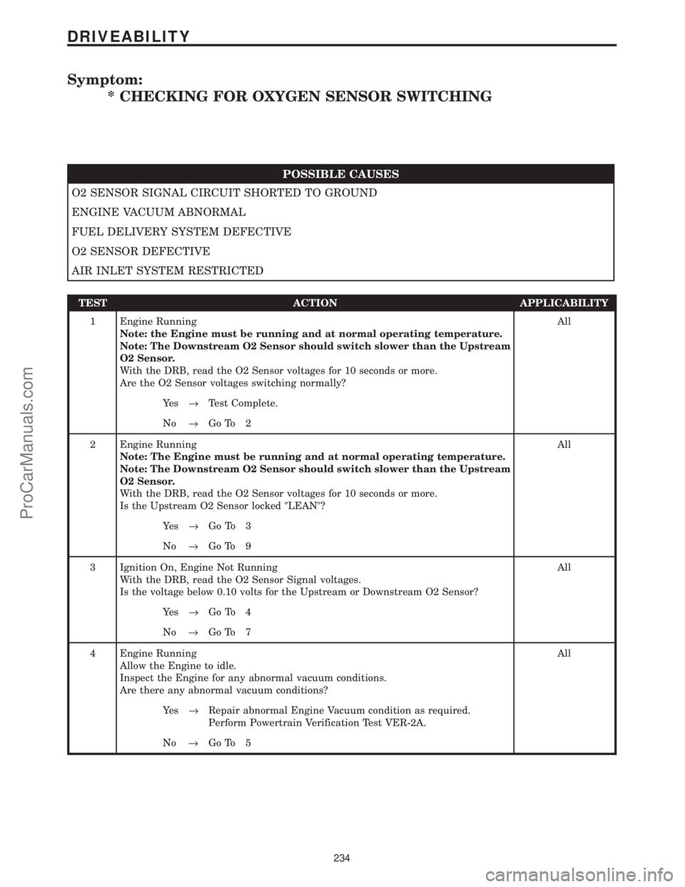
* CHECKING FOR OXYGEN SENSOR SWITCHING
POSSIBLE CAUSES
O2 SENSOR SIGNAL CIRCUIT SHORTED TO GROUND
ENGINE VACUUM ABNORMAL
FUEL DELIVERY SYSTEM DEFECTIVE
O2 SENSOR DEFECTIVE
AIR INLET SYSTEM RESTRICTED
TEST ACTION APPLICABILITY
1 Engine Running
Note: the Engine must be running and at normal operating temperature.
Note: The Downstream O2 Sensor should switch slower than the Upstream
O2 Sensor.
With the DRB, read the O2 Sensor voltages for 10 seconds or more.
Are the O2 Sensor voltages switching normally?All
Ye s®Test Complete.
No®Go To 2
2 Engine Running
Note: The Engine must be running and at normal operating temperature.
Note: The Downstream O2 Sensor should switch slower than the Upstream
O2 Sensor.
With the DRB, read the O2 Sensor voltages for 10 seconds or more.
Is the Upstream O2 Sensor locked9LEAN9?All
Ye s®Go To 3
No®Go To 9
3 Ignition On, Engine Not Running
With the DRB, read the O2 Sensor Signal voltages.
Is the voltage below 0.10 volts for the Upstream or Downstream O2 Sensor?All
Ye s®Go To 4
No®Go To 7
4 Engine Running
Allow the Engine to idle.
Inspect the Engine for any abnormal vacuum conditions.
Are there any abnormal vacuum conditions?All
Ye s®Repair abnormal Engine Vacuum condition as required.
Perform Powertrain Verification Test VER-2A.
No®Go To 5
234
DRIVEABILITY
ProCarManuals.com
Page 241 of 364

TEST ACTION APPLICABILITY
5 Ignition Off
Disconnect the Upstream or Downstream O2 Sensor Connector that the voltage is
below 0.10 volts.
Note: Check connectors - Clean/repair as necessary.
Disconnect the Powertrain Control Module.
Note: Check connectors - Clean/repair as necessary.
Using an Ohmmeter, measure the resistance between the O2 Sensor Signal Circuit
and a good ground.
Is the resistance below 5.0 ohms?All
Ye s®Repair the O2 Sensor Signal Circuit for a short to ground.
Perform Powertrain Verification Test VER-2A.
No®Go To 6
6 If there are no potential causes remaining, the Upstream or Downstream O2 Sensor
is assumed to be defective.
View repair options.All
Repair
Replace the Upstream or Downstream O2 Sensor that was below
0.10 volts.
Perform Powertrain Verification Test VER-2A.
7 Engine Running
Allow the Engine to idle.
Inspect the Engine for any abnormal vacuum conditions.
Are there any abnormal vacuum conditions?All
Ye s®Repair abnormal Engine Vacuum condition as required.
Perform Powertrain Verification Test VER-2A.
No®Go To 8
8 Engine Running
With the DRB, reset the Adaptive Fuel Memory.
Note: The engine must be running and at normal operating temperature.
Note: The Downstream O2 Sensor should switch slower than the Upstream
O2 Sensor.
With the DRB, read the O2 Sensor voltages for 10 seconds or more.
Are the O2 Sensor voltages switching normally?All
Ye s®Test Complete.
No®Refer to symptom * CHECKING THE ENGINE MECHANICAL
SYSTEMS in the DRIVEABILITY category.
9 Ignition Off
Install a Fuel Pressure Gauge to the Fuel Line. Use special tools if necessary.
Turn ignition on.
With the DRB, actuate the ASD Fuel System Test.
Allow Fuel Pressure to stabilize.
With the DRB, stop Fuel System Test. Monitor the Pressure Gauge for 1 minute.
Is the Fuel Pressure below 10 psi?All
Ye s®If Fuel Pump and Lines are OK, replace leaking Injector(s) as
necessary.
Perform Powertrain Verification Test VER-2A.
No®Go To 10
235
DRIVEABILITY
* CHECKING FOR OXYGEN SENSOR SWITCHING ÐContinued
ProCarManuals.com
Page 248 of 364

Symptom:
* CHECKING IDLE AIR CONTROL MOTOR
POSSIBLE CAUSES
ENGINE SPEED WITHIN TOLERANCE
IAC MOTOR CONNECTOR OBSERVABLE DEFECT
ENGINE HAS VACUUM LEAKS
IAC MOTOR DEFECTIVE
TEST ACTION APPLICABILITY
1 Engine Running
With the DRB in actuator tests, set the engine speed to 1400 RPM and then to 900
RPM.
Did the engine RPM go from 1400 RPM to 900 RPM?All
Ye s®With the DRB, stop all tests, test complete.
No®Go To 2
2 Engine Running
Inspect the engine for any vacuum leak(s).
Is there any vacuum leaks?All
Ye s®Repair Vacuum Leak(s) as necessary.
Perform Powertrain Verification Test VER-2A.
No®Go To 3
3 Turn the ignition off.
Disconnect the IAC motor harness connector.
Start the engine and allow it to idle.
Using a test light connected to ground, probe the IAC Driver #1 circuit.
Repeat the above test for the remaining IAC Driver circuits.
Did the test light turn on and off at any time for each IAC driver circuit?All
Ye s®Go To 4
No®Go To 5
4 Turn the ignition off.
Disconnect the IAC motor harness connector.
Start the engine and allow it to idle.
Using a test light connected to battery positive, probe the IAC Driver #1 circuit.
Repeat the above test for the remaining IAC Driver circuits.
Did the test light turn on and off at any time for each IAC driver circuit?All
Ye s®Go To 6
No®Go To 8
242
DRIVEABILITY
ProCarManuals.com
Page 251 of 364

Symptom:
* CHECKING MAP SENSOR CALIBRATION
POSSIBLE CAUSES
MAP SENSOR DEFECTIVE
TEST ACTION APPLICABILITY
1 Ignition Off
Tee-in a Vacuum Gauge to a Manifold Vacuum source.
Start the engine.
Allow engine to idle.
Note: If engine will not idle, maintain a constant RPM above idle.
Using the DRB, read MAP Sensor Vacuum.
Is the reading within 1 inch of the teed-in Vacuum Gauge?All
Ye s®Go To 2
No®Replace the MAP Sensor.
Perform Verification Test VER-2A.
2 Ignition Off
Disconnect the MAP Sensor Harness Connector.
Ignition On.
Using a voltmeter, measure the 5±volt supply circuit.
Is the voltage above 4.0 volts?All
Ye s®Test Complete.
No®Repair the open 5±volt supply circuit.
Perform Verification Test VER-2A.
245
DRIVEABILITY
ProCarManuals.com
Page 259 of 364
Symptom:
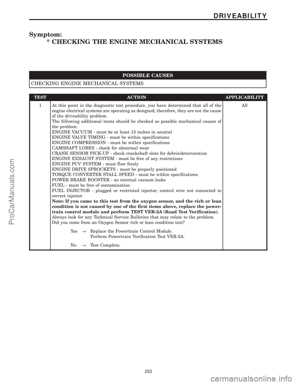
* CHECKING THE ENGINE MECHANICAL SYSTEMS
POSSIBLE CAUSES
CHECKING ENGINE MECHANICAL SYSTEMS
TEST ACTION APPLICABILITY
1 At this point in the diagnostic test procedure, you have determined that all of the
engine electrical systems are operating as designed; therefore, they are not the cause
of the driveability problem.
The following additional items should be checked as possible mechanical causes of
the problem:
ENGINE VACUUM - must be at least 13 inches in neutral
ENGINE VALVE TIMING - must be within specifications
ENGINE COMPRESSION - must be within specifications
CAMSHAFT LOBES - check for abnormal wear
CRANK SENSOR PICK-UP - check crankshaft slots for debris/deterioration
ENGINE EXHAUST SYSTEM - must be free of any restrictions
ENGINE PCV SYSTEM - must flow freely
ENGINE DRIVE SPROCKETS - must be properly positioned
TORQUE CONVERTER STALL SPEED - must be within specifications
POWER BRAKE BOOSTER - no internal vacuum leaks
FUEL - must be free of contamination
FUEL INJECTOR - plugged or restricted injector; control wire not connected to
correct injector
Note: If you came to this test from the oxygen sensor, and the rich or lean
condition is not caused by one of the first items above, replace the power-
train control module and perform TEST VER-2A (Road Test Verification).
Always look for any Technical Service Bulletins that may relate to the problem.
Did you come from an Oxygen Sensor rich or lean condition test?All
Ye s®Replace the Powertrain Control Module.
Perform Powertrain Verification Test VER-2A.
No®Test Complete.
253
DRIVEABILITY
ProCarManuals.com
Page 263 of 364

TEST ACTION APPLICABILITY
1 Ignition Off
Note: A misadjusted Brake Switch can cause this code to set.
Does the Brake Switch need to be adjusted?All
Ye s®Adjust Brake Switch as necessary.
No®Go To 2
2 Ignition Off
Disconnect the Speed Control Servo 4-Way Connector.
Note: Check connectors - Clean/repair as necessary.
Note: Ensure the Brake pedal is not depressed during the following steps.
Engine off. Ignition key on and S/C On/Off Switch ON.
Using a Voltmeter, measure the voltage of the S/C Brake Switch Output Circuit at
Speed Control Servo Connector.
Is the voltage above 10.0 volts?All
Ye s®Go To 3
No®Go To 10
3 Ignition off.
Disconnect the Speed Control Servo Connector.
Note: Check connectors - Clean/repair as necessary.
Using an Ohmmeter, measure resistance of the Gnd Circuit at Servo Connector.
Is the resistance below 5.0 ohms?All
Ye s®Go To 4
No®Repair the open Ground Circuit.
Perform Powertrain Verification Test VER-4A.
4 Ignition off
Disconnect the Powertrain Control Module.
Note: Check connectors - Clean/repair as necessary.
Note: Ensure the Brake pedal is not depressed during the following steps.
With an ohmmeter, test the resistance from the S/C Power Supply Circuit to the S/C
Vent Solenoid at PCM.
Is the resistance between 35 ohms and 55 ohms?All
Ye s®Go To 5
No®Go To 7
5 Ignition off
Disconnect Powertrain Control Module.
Note: Check connectors - Clean/repair as necessary.
Note: Ensure the Brake Pedal is not depressed during the following steps.
With an ohmmeter, test the resistance from the S/C Power Supply Circuit to the S/C
Vacuum Solenoid Control at PCM.
Is the resistance between 35 ohms and 55 ohms?All
Ye s®Go To 6
No®Go To 7
257
SPEED CONTROL
P-1595 SPEED CONTROL SOLENOID CIRCUITS ÐContinued
ProCarManuals.com
Page 272 of 364

Symptom:
* CHECKING SPEED CONTROL OPERATION
POSSIBLE CAUSES
BRAKE SWITCH DEFECTIVE
GROUND CIRCUIT OPEN
S/C BRAKE SWITCH OUTPUT CIRCUIT SHORTED TO GROUND
SPEED CONTROL BRAKE SWITCH OUTPUT SUPPLY CKT OPEN
SPEED CONTROL ON/OFF/SET SWITCH DEFECTIVE
SPEED CONTROL POWER SUPPLY CIRCUIT OPEN
SPEED CONTROL POWER SUPPLY CIRCUIT SHORTED/GROUND
SPEED CONTROL SERVO CONNECTOR OBSERVABLE DEFECT
SPEED CONTROL SWITCH DEFECTIVE
CLOCK SPRING DEFECTIVE
SPEED CONTROL SERVO DEFECTIVE
SPEED CONTROL THROTTLE CABLE DEFECTIVE
SPEED CONTROL VACUUM SUPPLY LEAKS OR RESTRICTED
PCM DEFECTIVE (SPEED CONTROL OPERATION)
VACUUM RESERVOIR DEFECTIVE
TEST ACTION APPLICABILITY
1 Ignition On, Engine Not Running
With the DRB, monitor the Speed Control Switch inputs.
While observing display, press the Speed Control ON/OFF switch.
Does the DRB show S/C ON/OFF switch9ON9?All
Ye s®Go To 2
No®Refer to symptom SPEED CONTROL ON/OFF SWITCH in the
SPEED CONTROL category.
2 Ignition On, Engine Not Running
Press the S/C ON/OFF button to select S/C ªON.º
With the DRB, monitor the Speed Control Switch inputs.
While observing the DRB, press the ACCEL/RESUME/CANCEL and DECEL
switches several times.
Do all of the Switches toggle correctly between pressed and released?All
Ye s®Go To 3
No®Go To 25
266
SPEED CONTROL
ProCarManuals.com