engine vacuum CHRYSLER VOYAGER 2000 Diagnostic Manual
[x] Cancel search | Manufacturer: CHRYSLER, Model Year: 2000, Model line: VOYAGER, Model: CHRYSLER VOYAGER 2000Pages: 364, PDF Size: 2.17 MB
Page 82 of 364

TEST ACTION APPLICABILITY
3 Ignition On, Engine Not Running.
With the DRB, read TPS Sensor voltage. Throttle must be against stop.
Is the voltage 0.92 or less with the Throttle closed?All
Ye s®Go To 4
No®Replace the Throttle Position Sensor.
Perform Powertrain Verification Test VER-5A.
4 Turn ignition On.
With the DRB in sensors, read the ªEngine Coolant Tmp Degº value.
Note: If engine coolant temperature is above 82ÉC (180ÉF), allow the engine
to cool until 62ÉC (150ÉF) is reached.
Start the Engine.
While monitoring the DRB, allow the engine to reach normal operating temperature
above 82ÉC (180ÉF).
Did the engine coolant temperature value reach 82ÉC (180ÉF) or above?All
Ye s®Go To 5
No®Replace the Engine Coolant Temperature Sensor.
Perform Powertrain Verification Test VER-5A.
5 Turn ignition On.
With the DRB in sensors, read the88Eng Coolant Tmp Deg'' value
Note: If engine coolant temperature is above 82ÉC (180ÉF), allow the engine
to cool until 62ÉC (150ÉF) is reached.
Start the Engine.
While monitoring the DRB, allow the engine to reach normal operating temperature
above 82ÉC (180ÉF).
Was the coolant temperature value increase a smooth transition?All
Ye s®Go To 6
No®Replace the Engine Coolant Temperature Sensor.
Perform Verificatino Test VER-5A.
6 Turn ignition off.
Connect a Vacuum Gauge to a Manifold Vacuum source.
Start the engine.
Allow the engine to idle.
Note: If engine will not idle, maintain a constant RPM above idle.
Using the DRB in Sensors, read the MAP Sensor vacuum value.
Is the DRB reading within 19of the Vacuum Gauge reading?All
Ye s®Go To 7
No®Replace the MAP Sensor.
Perform Powertrain Verification Test VER-5A.
76
DRIVEABILITY
P-0171±1/1 FUEL SYSTEM LEAN ÐContinued
ProCarManuals.com
Page 84 of 364

TEST ACTION APPLICABILITY
11 Check for any of the following conditions/mechanical problems.
ENGINE VACUUM Ð must be at least 13 inches in neutral
ENGINE VALVE TIMING Ð must be within specifications
ENGINE COMPRESSION Ð must be within specifications
ENGINE EXHAUST SYSTEM Ð must be free of any restrictions or leaks
ENGINE PVC SYSTEM Ð must flow freely
TORQUE CONVERTER STALL SPEED Ð must be within specifications
POWER BRAKE BOOSTER Ð no internal vacuum leaks
FUEL- must be free of contamination
FUEL INJECTOR Ð plugged or restricted injector; control wire not connected to
correct injector.
Are there any engine mechanical problems?All
Ye s®Repair as necessary.
Perform FUEL SYSTEM/MISFIRE MONITOR VERIFICATION
TEST
No®Go To 12
12 Turn ignition off.
Warning: The fuel system is under constant pressure (even with the engine
off). Before testing or servicing any fuel system hose, fitting or line, the fuel
system pressure must be released.
Disconnect the fuel supply line at the fuel rail.
Connect fuel line adapter #6539(5/169) or #6631 (3/89) to the disconnected fuel supply
line. Insert the other end of the adapter into a graduated container.
Caution: Do not operate the fuel pump for more than 7 seconds in the next
step. Fuel pump module reservoir may run empty and damage to the fuel
pump may result.
Specification: A good fuel pump will deliver at least 1/4 liter of fuel in 7
seconds.
With the DRB, actuate the ASD Fuel System test for 7 seconds.
Is the fuel pump capacity within specification?All
Ye s®Test Complete.
No®Check for a kinked/damaged fuel supply line between the fuel
tank and fuel rail. If OK, replace the fuel filter/pressure regulator.
Caution: Stop ALL Actuations.
13 The conditions required to set the DTC are no longer present.
With the DRB read and record the freeze frame data and the ªFuel System Similar
Conditions Windowº data.
Utilize the data and try to duplicate the operating conditions at which the DTC was
set. Pay particular attention to the ECT and RPM for added diagnostics.
Note: Refer to any TSB's that may apply to the symptom.
Test Complete
Repair
Test Complete.
78
DRIVEABILITY
P-0171±1/1 FUEL SYSTEM LEAN ÐContinued
ProCarManuals.com
Page 86 of 364

TEST ACTION APPLICABILITY
3 Ignition On, Engine Not Running.
With the DRB, read TP Sensor voltage. Throttle must be against stop.
Is the voltage 0.92 or less with the Throttle closed?All
Ye s®Go To 4
No®Replace the Throttle Position Sensor.
Perform Powertrain Verification Test VER-5A.
4 Turn ignition on.
With the DRB in sensors, read the ªEng Coolant Tmp Degº value.
Note: If engine coolant temperature is above 82ÉC (180ÉF), allow the engine
to cool until 62ÉC (150ÉF) is reached.
Start the Engine.
While monitoring the DRB, allow the engine to reach normal operating temperature
above 82ÉC (180ÉF).
Did the engine coolant temperature value reach 180ÉF or above?All
Ye s®Go To 5
No®Replace the Engine Coolant Temperature Sensor.
Perform Powertrain Verification Test VER-5A.
5 Turn ignition On.
With the DRB in sensors, read the ªEng Coolant Tmp Deg'' value
Note: If engine coolant temperature is above 82ÉC (180ÉF), allow the engine
to cool until 62ÉC (150ÉF) is reached.
Start the Engine.
While monitoring the DRB, allow the engine to reach normal operating temperature
above 82ÉC (180ÉF).
Was the coolant temperature value increase a smooth transition?All
Ye s®Go To 6
No®Replace the Engine Coolant Temperature Sensor.
Perform Verification Test VER-5A.
6 Turn ignition off.
Connect a Vacuum Gauge to a Manifold Vacuum source.
Start the engine.
Allow the engine to idle.
Note: If engine will not idle, maintain a constant RPM above idle.
Using the DRB in Sensors, read the MAP Sensor vacuum value.
Is the DRB reading within 19of the Vacuum Gauge reading?All
Ye s®Go To 7
No®Replace the MAP Sensor.
Perform Powertrain Verification Test VER-5A.
7Note: Engine must be at operating temp and in closed loop to perform this
test.
Start engine and run until operating temp and closed loop mode is reached.
With the DRB under System Tests, go to ªPurge Vapors Test''. Observe the Short
Term Adaptive value and press 3 to flow.
Note: Short Term Adaptive should change.
Did the Short Term Adaptive value change?All
Ye s®Go To 8
No®Refer to symptom *CHECKING EVAPORATIVE EMISSION
SYSTEM in the DRIVEABILITY category.
80
P0172 -1/1 FUEL SYSTEM RICH ÐContinued
ProCarManuals.com
Page 87 of 364

TEST ACTION APPLICABILITY
8 Turn ignition off.
Warning: The fuel system is under a constant pressure (even with the engine
off). Before testing or servicing any fuel system hose, fitting or line, the fuel
system pressure must be released.
Remove the pressure test port cap at the fuel rail test port. Connect a fuel pressure
gauge to the test port pressure fitting on the fuel rail.
Ignition on. With the DRB, actuate the ASD Fuel System test and observe the fuel
pressure gauge.
Note: Fuel pressure specification is 49.2 psi +/þ 5 psi.
Choose a conclusion that best matches your fuel pressure reading.All
Below Specification
Go To 9
Within Specification
Go To 13
Above Specification
Replace the fuel filter/pressure regulator.
Caution: Stop ALL Actuations.
9 Check for any of the following conditions/mechanical problems.
ENGINE VACUUM Ð must be at least 13 inches in neutral
ENGINE VALVE TIMING Ð must be within specifications
ENGINE COMPRESSION Ð must be within specifications
ENGINE EXHAUST SYSTEM Ð must be free of any restrictions or leaks.
ENGINE PVC SYSTEM Ð must flow freely
TORQUE CONVERTER STALL SPEED Ð must be within specifications
POWER BRAKE BOOSTER Ð no internal vacuum leaks
FUEL - must be free of contamination
FUEL INJECTOR Ð plugged or restricted injector; control wire not connected to
correct injector
Are there any engine mechanical problems?All
Ye s®Repair as necessary.
Perform FUEL SYSTEM/MISFIRE MONITOR VERIFICATION
TEST
No®Go To 10
10 Turn ignition off.
Warning: The fuel system is under a constant pressure (even with the engine
off). Before testing or servicing any fuel system hose, fitting or line, the fuel
system pressure must be released.
Raise vehicle on hoist, and disconnect the fuel pressure line at the fuel pump module.
Install special 5/169fuel line adapter tool #6539 between disconnected fuel line and
the fuel pump module.
Attach a fuel pressure test gauge to the ªT'' fitting on tool #6539.
Ignition on. With the DRB, actuate the ASD Fuel System test and observe the fuel
pressure gauge.
Note: Fuel pressure specification is 49.2 psi +/- 5 psi.
Is the fuel pressure within specification now?All
Ye s®Repair the restriction in the chassis fuel supply line between the
fuel tank and fuel rail.
No®Go to 11
Caution: Stop ALL Actuations.
81
P0172 -1/1 FUEL SYSTEM RICH ÐContinued
ProCarManuals.com
Page 88 of 364

TEST ACTION APPLICABILITY
11Warning: The fuel system is under a constant pressure (even with the engine
off). Before testing or servicing any fuel system hose, fitting or line, the fuel
system pressure must be released.
Remove the Fuel Pump Module and inspect the Fuel Inlet Strainer.
Is the Fuel Inlet Strainer plugged?All
Ye s®Replace the Fuel Inlet Strainer.
No®Go To 12
12 If there are no potential causes remaining, the Fuel Pump Module is assumed to be
defective.
View repair options.All
Repair
Replace the Fuel Pump Module
13 Check for any of the following conditions/mechanical problems.
ENGINE VACUUM Ð must be at least 13 inches in neutral
ENGINE VALVE TIMING Ð must be within specifications
ENGINE COMPRESSION Ð must be within specifications
ENGINE EXHAUST SYSTEM Ð must be free of any restrictions or leaks.
ENGINE PVC SYSTEM Ð must flow freely
TORQUE CONVERTER STALL SPEED Ð must be within specifications
POWER BRAKE BOOSTER Ð no internal vacuum leaks
FUEL - must be free of contamination
FUEL INJECTOR Ð plugged or restricted injector; control wire not connected to
correct injector
Are there any engine mechanical problems?All
Ye s®Repair as necessary.
Perform FUEL SYSTEM/MISFIRE MONITOR VERIFICATION
TEST
No®Test Complete.
14 The conditions required to set the DTC are no longer present.
With the DRB read and record the freeze frame data and the ªFuel System Similar
Conditions Window'' data.
Utilize the data and try to duplicate the operating conditions at which the DTC was
set. Pay particular attention to the ECT and RPM for added diagnostics.
Note: Refer to any TSB's that may apply to the symptom.
Test Complete
Repair
Test Complete.
82
P0172 -1/1 FUEL SYSTEM RICH ÐContinued
ProCarManuals.com
Page 107 of 364

POSSIBLE CAUSES
OTHER POSSIBLE CAUSES FOR MIS-FIRE
CAM, CRANK, VALVE TIMING, OR VACUUM PROBLEM
ELECTRONIC IGNITION COIL OUTPUT LOW
ENGINE MECHANICAL PROBLEM
SECONDARY IGNITION PATTERN IRREGULAR
FUEL CONTAMINATION
FUEL PRESSURE LEAK DOWN OUT OF SPECIFICATION
FUEL PUMP AMPERAGE OUT OF SPECIFICATION
FUEL PUMP CAPACITY OUT OF SPECIFICATION
FUEL PUMP PRESSURE OUT OF SPECIFICATION
MIS-FIRE DOES NOT REOCCUR
TEST ACTION APPLICABILITY
1 With the DRB, read the DTCs.
Is the MIS-FIRE GOOD TRIP counter displayed and equal to zero?All
Ye s®Go To 2
No®Go To 3
2 At this time the conditions that set this fault are present.
With the DRB, read the FREEZE FRAME and SIMILAR CONDITIONS WINDOWS.
Attempt to operate the vehicle in the similar conditions.
When the vehicle is operating in the SIMILAR CONDITIONS WINDOW, go to the
WHICH CYLINDER IS MISFIRING screen.
Is the DRB counting mis-fires at this time?All
Ye s®Go To 4
No®Go To 3
3 At this time the mis-fire does not exist or is an intermittent problem.
With the DRB, read the FREEZE FRAME and SIMILAR CONDITIONS WINDOW.
With these screens, attempt to duplicate the condition that has set this fault.
While using FREEZE FRAME pay particular attention to the fault setting condi-
tions, such as speed, temp, load, and map vacuum.
Does the mis-fire reoccur?All
Ye s®Go To 4
No®Mis-fire no longer exists.
Perform VERIFICATION TEST VER-5A2.
4 With the DRB, read the FREEZE FRAME DATA.
Use the freeze frame data and attempt to determine the cause.
In the FREEZE FRAME, are the adaptive fuel percentages greater than +/- 15%?All
Ye s®Go To 5
No®Go To 10
101
DRIVEABILITY
P-0300 MULTIPLE CYLINDER MIS-FIRE ÐContinued
ProCarManuals.com
Page 108 of 364

TEST ACTION APPLICABILITY
5 With an appropriate container, obtain a fuel sample from the vehicle.
Is the fuel free from contamination?All
Ye s®Go To 6
No®Replace contaminated fuel and clean system.
Perform VERIFICATION TEST VER-5A2.
6 Perform Fuel Pressure Leak Down Test per service instructions.
Did the Fuel Pressure Leak Down Test pass?All
Ye s®Go To 7
No®Relieve fuel pressure and repair as necessary.
Perform VERIFICATION TEST VER-5A2.
7 Perform Fuel Pump Amperage Test per service instructions.
Did the Fuel Pump Amperage Test pass?All
Ye s®Go To 8
No®Relieve fuel pressure and repair as necessary.
Perform VERIFICATION TEST VER-5A2.
8 Perform Fuel Pump Capacity Test per service instructions.
Did the Fuel Pump Capacity Test pass?All
Ye s®Go To 9
No®Relieve fuel pressure and repair as necessary.
Perform VERIFICATION TEST VER-5A2.
9 Perform Fuel Pump Pressure Test per service instructions.
Did the Fuel Pump Pressure Test pass?All
Ye s®Go To 10
No®Relieve fuel pressure and repair as necessary.
Perform VERIFICATION TEST VER-5A2.
10 With the DRB, read the FREEZE FRAME DATA.
Use the freeze frame data and attempt to determine the cause.
In the FREEZE FRAME, is the LOAD VALUE over 50% and the temp normal
operating temp normal?All
Ye s®Go To 12
No®Go To 11
11 With the DRB, read the FREEZE FRAME window.
Use the freeze frame data and attempt to determine the cause.
In the FREEZE FRAME, is the ENGINE RPM over 3000 and the operating temp
normal?All
Ye s®Lab scope cam and crank sensor, check valve timing, running
vacuum test.
Perform VERIFICATION TEST VER-5A2.
No®Go To 14
102
DRIVEABILITY
P-0300 MULTIPLE CYLINDER MIS-FIRE ÐContinued
ProCarManuals.com
Page 109 of 364
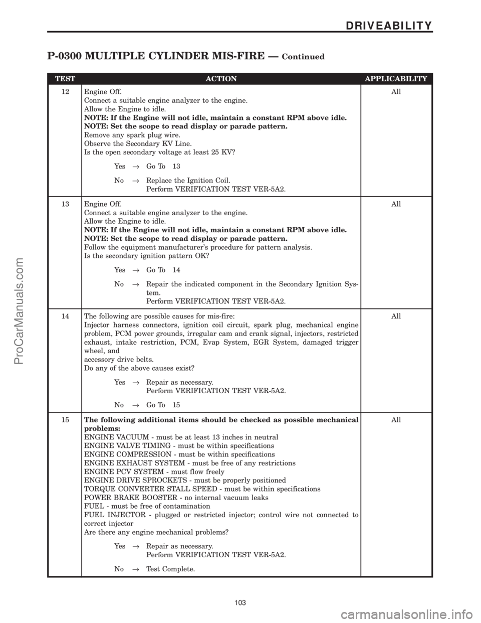
TEST ACTION APPLICABILITY
12 Engine Off.
Connect a suitable engine analyzer to the engine.
Allow the Engine to idle.
NOTE: If the Engine will not idle, maintain a constant RPM above idle.
NOTE: Set the scope to read display or parade pattern.
Remove any spark plug wire.
Observe the Secondary KV Line.
Is the open secondary voltage at least 25 KV?All
Ye s®Go To 13
No®Replace the Ignition Coil.
Perform VERIFICATION TEST VER-5A2.
13 Engine Off.
Connect a suitable engine analyzer to the engine.
Allow the Engine to idle.
NOTE: If the Engine will not idle, maintain a constant RPM above idle.
NOTE: Set the scope to read display or parade pattern.
Follow the equipment manufacturer's procedure for pattern analysis.
Is the secondary ignition pattern OK?All
Ye s®Go To 14
No®Repair the indicated component in the Secondary Ignition Sys-
tem.
Perform VERIFICATION TEST VER-5A2.
14 The following are possible causes for mis-fire:
Injector harness connectors, ignition coil circuit, spark plug, mechanical engine
problem, PCM power grounds, irregular cam and crank signal, injectors, restricted
exhaust, intake restriction, PCM, Evap System, EGR System, damaged trigger
wheel, and
accessory drive belts.
Do any of the above causes exist?All
Ye s®Repair as necessary.
Perform VERIFICATION TEST VER-5A2.
No®Go To 15
15The following additional items should be checked as possible mechanical
problems:
ENGINE VACUUM - must be at least 13 inches in neutral
ENGINE VALVE TIMING - must be within specifications
ENGINE COMPRESSION - must be within specifications
ENGINE EXHAUST SYSTEM - must be free of any restrictions
ENGINE PCV SYSTEM - must flow freely
ENGINE DRIVE SPROCKETS - must be properly positioned
TORQUE CONVERTER STALL SPEED - must be within specifications
POWER BRAKE BOOSTER - no internal vacuum leaks
FUEL - must be free of contamination
FUEL INJECTOR - plugged or restricted injector; control wire not connected to
correct injector
Are there any engine mechanical problems?All
Ye s®Repair as necessary.
Perform VERIFICATION TEST VER-5A2.
No®Test Complete.
103
DRIVEABILITY
P-0300 MULTIPLE CYLINDER MIS-FIRE ÐContinued
ProCarManuals.com
Page 110 of 364

Symptom List:
P-0305 CYLINDER #5 MIS-FIRE
P-0306 CYLINDER #6 MIS-FIRE
Test Note: All symptoms listed above are diagnosed using the same tests.
The title for the tests will be P-0305 CYLINDER #5 MIS-FIRE.
When Monitored and Set Condition:
P-0305 CYLINDER #5 MIS-FIRE
When Monitored: With the engine running, after successfully performing Crank Sensor
learn.
Set Condition: When more than a 2% misfire rate is measured during two trips, or with
a 10% to 30% misfire rate during one trip.
P-0306 CYLINDER #6 MIS-FIRE
When Monitored: With the engine running, after successfully performing Crank Sensor
learn.
Set Condition: When more than a 2% misfire rate is measured during two trips, or with
a 10% to 30% misfire rate during one trip.
POSSIBLE CAUSES
OTHER POSSIBLE CAUSES FOR MIS-FIRE
CAM, CRANK, VALVE TIMING, OR VACUUM PROBLEM
ELECTRONIC IGNITION COIL OUTPUT LOW
ENGINE MECHANICAL PROBLEM
SECONDARY IGNITION PATTERN IRREGULAR
FUEL CONTAMINATION
FUEL PRESSURE LEAK DOWN OUT OF SPECIFICATION
FUEL PUMP AMPERAGE OUT OF SPECIFICATION
FUEL PUMP CAPACITY OUT OF SPECIFICATION
FUEL PUMP PRESSURE OUT OF SPECIFICATION
MIS-FIRE DOES NOT REOCCUR
TEST ACTION APPLICABILITY
1 With the DRB, read the DTCs.
Is the MIS-FIRE GOOD TRIP counter displayed and equal to zero?ENGINE - 3.0L V6
and/or ENGINE -
3.3L V6 and/or EN-
GINE - 3.8L V6
and/or ENGINE -
3.3L V6 FFV Ye s®Go To 2
No®Go To 3
104
DRIVEABILITY
ProCarManuals.com
Page 111 of 364

TEST ACTION APPLICABILITY
2 At this time the conditions that set this fault are present.
With the DRB, read the FREEZE FRAME DATA and SIMILAR CONDITIONS
WINDOWS.
Attempt to operate the vehicle in the similar conditions.
When the vehicle is operating in the SIMILAR CONDITIONS window, go to the
WHICH CYLINDER IS MISFIRING monitor.
Is the DRB counting mis-fires at this time?ENGINE - 3.0L V6
and/or ENGINE -
3.3L V6 and/or EN-
GINE - 3.8L V6
and/or ENGINE -
3.3L V6 FFV
Ye s®Go To 4
No®Go To 3
3 At this time the mis-fire does not exist or is an intermittent problem.
With the DRB, read the FREEZE FRAME DATA and SIMILAR CONDITIONS
WINDOW.
With these screens, attempt to duplicate the condition that has set this fault.
While using FREEZE FRAME DATA pay particular attention to the fault setting
conditions, such as speed, temp, load, and map vacuum.
Does the mis-fire reoccur?ENGINE - 3.0L V6
and/or ENGINE -
3.3L V6 and/or EN-
GINE - 3.8L V6
and/or ENGINE -
3.3L V6 FFV
Ye s®Go To 4
No®Mis-fire no longer exists.
Perform VERIFICATION TEST VER-5A2.
4 With the DRB, read the FREEZE FRAME DATA.
Use the freeze frame data and attempt to determine the cause of the misfire.
In the FREEZE FRAME, are the adaptive fuel percentages greater than +/- 15
percent?ENGINE - 3.0L V6
and/or ENGINE -
3.3L V6 and/or EN-
GINE - 3.8L V6
and/or ENGINE -
3.3L V6 FFV
Ye s®Go To 5
No®Go To 10
5 With an appropriate container, obtain a fuel sample from the vehicle.
Is the fuel free from contamination?ENGINE - 3.0L V6
and/or ENGINE -
3.3L V6 and/or EN-
GINE - 3.8L V6
and/or ENGINE -
3.3L V6 FFV
Ye s®Go To 6
No®Replace contaminated fuel and clean system.
Perform VERIFICATION TEST VER-5A2.
6 Perform Fuel Pressure Leak Down Test per service instructions.
Did the Fuel Pressure Leak Down Test pass?ENGINE - 3.0L V6
and/or ENGINE -
3.3L V6 and/or EN-
GINE - 3.8L V6
and/or ENGINE -
3.3L V6 FFV
Ye s®Go To 7
No®Relieve fuel pressure and repair as necessary.
Perform VERIFICATION TEST VER-5A2.
105
DRIVEABILITY
P-0305 CYLINDER #5 MIS-FIRE ÐContinued
ProCarManuals.com