clock CHRYSLER VOYAGER 2001 Service Manual
[x] Cancel search | Manufacturer: CHRYSLER, Model Year: 2001, Model line: VOYAGER, Model: CHRYSLER VOYAGER 2001Pages: 4284, PDF Size: 83.53 MB
Page 2449 of 4284
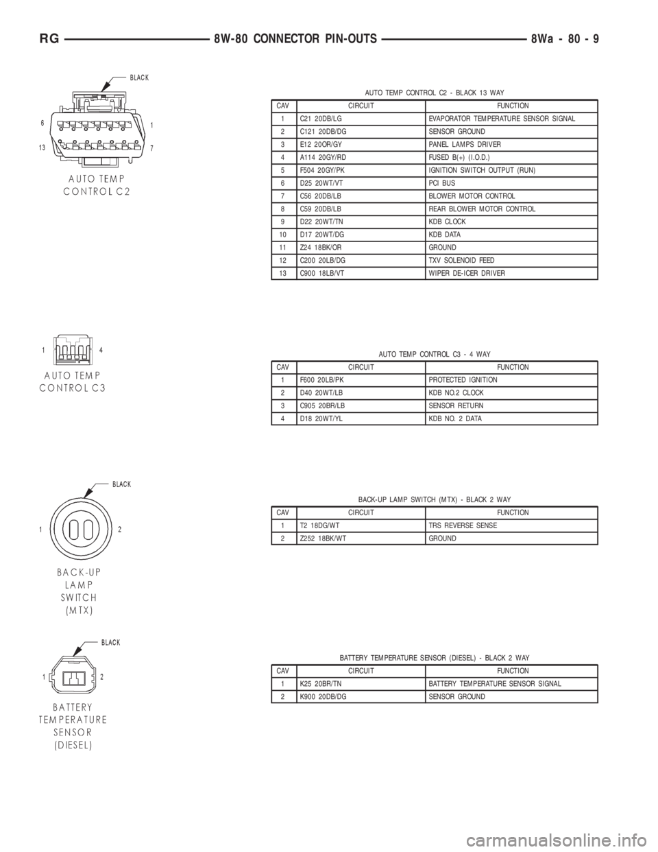
AUTO TEMP CONTROL C2 - BLACK 13 WAY
CAV CIRCUIT FUNCTION
1 C21 20DB/LG EVAPORATOR TEMPERATURE SENSOR SIGNAL
2 C121 20DB/DG SENSOR GROUND
3 E12 20OR/GY PANEL LAMPS DRIVER
4 A114 20GY/RD FUSED B(+) (I.O.D.)
5 F504 20GY/PK IGNITION SWITCH OUTPUT (RUN)
6 D25 20WT/VT PCI BUS
7 C56 20DB/LB BLOWER MOTOR CONTROL
8 C59 20DB/LB REAR BLOWER MOTOR CONTROL
9 D22 20WT/TN KDB CLOCK
10 D17 20WT/DG KDB DATA
11 Z24 18BK/OR GROUND
12 C200 20LB/DG TXV SOLENOID FEED
13 C900 18LB/VT WIPER DE-ICER DRIVER
AUTO TEMP CONTROL C3-4WAY
CAV CIRCUIT FUNCTION
1 F600 20LB/PK PROTECTED IGNITION
2 D40 20WT/LB KDB NO.2 CLOCK
3 C905 20BR/LB SENSOR RETURN
4 D18 20WT/YL KDB NO. 2 DATA
BACK-UP LAMP SWITCH (MTX) - BLACK 2 WAY
CAV CIRCUIT FUNCTION
1 T2 18DG/WT TRS REVERSE SENSE
2 Z252 18BK/WT GROUND
BATTERY TEMPERATURE SENSOR (DIESEL) - BLACK 2 WAY
CAV CIRCUIT FUNCTION
1 K25 20BR/TN BATTERY TEMPERATURE SENSOR SIGNAL
2 K900 20DB/DG SENSOR GROUND
RG8W-80 CONNECTOR PIN-OUTS8Wa-80-9
Page 2485 of 4284
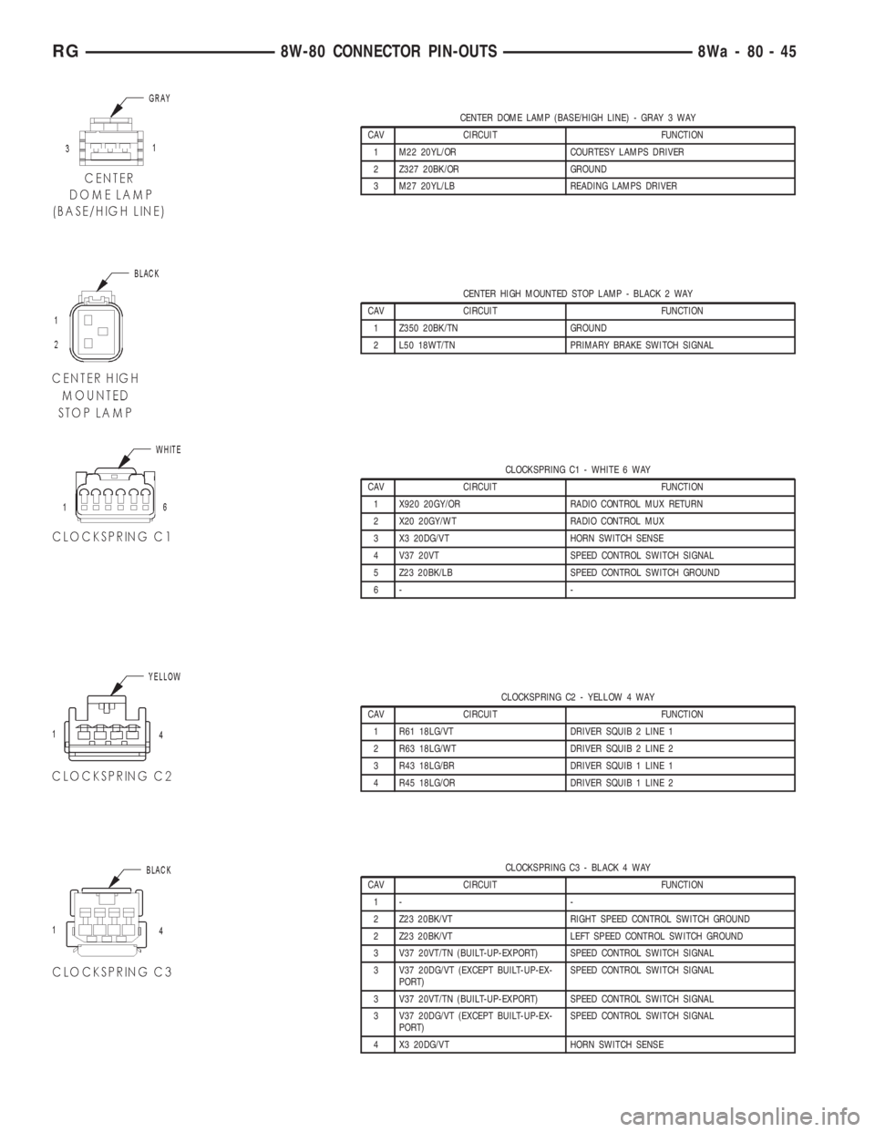
CENTER DOME LAMP (BASE/HIGH LINE) - GRAY 3 WAY
CAV CIRCUIT FUNCTION
1 M22 20YL/OR COURTESY LAMPS DRIVER
2 Z327 20BK/OR GROUND
3 M27 20YL/LB READING LAMPS DRIVER
CENTER HIGH MOUNTED STOP LAMP - BLACK 2 WAY
CAV CIRCUIT FUNCTION
1 Z350 20BK/TN GROUND
2 L50 18WT/TN PRIMARY BRAKE SWITCH SIGNAL
CLOCKSPRING C1 - WHITE 6 WAY
CAV CIRCUIT FUNCTION
1 X920 20GY/OR RADIO CONTROL MUX RETURN
2 X20 20GY/WT RADIO CONTROL MUX
3 X3 20DG/VT HORN SWITCH SENSE
4 V37 20VT SPEED CONTROL SWITCH SIGNAL
5 Z23 20BK/LB SPEED CONTROL SWITCH GROUND
6- -
CLOCKSPRING C2 - YELLOW 4 WAY
CAV CIRCUIT FUNCTION
1 R61 18LG/VT DRIVER SQUIB 2 LINE 1
2 R63 18LG/WT DRIVER SQUIB 2 LINE 2
3 R43 18LG/BR DRIVER SQUIB 1 LINE 1
4 R45 18LG/OR DRIVER SQUIB 1 LINE 2
CLOCKSPRING C3 - BLACK 4 WAY
CAV CIRCUIT FUNCTION
1- -
2 Z23 20BK/VT RIGHT SPEED CONTROL SWITCH GROUND
2 Z23 20BK/VT LEFT SPEED CONTROL SWITCH GROUND
3 V37 20VT/TN (BUILT-UP-EXPORT) SPEED CONTROL SWITCH SIGNAL
3 V37 20DG/VT (EXCEPT BUILT-UP-EX-
PORT)SPEED CONTROL SWITCH SIGNAL
3 V37 20VT/TN (BUILT-UP-EXPORT) SPEED CONTROL SWITCH SIGNAL
3 V37 20DG/VT (EXCEPT BUILT-UP-EX-
PORT)SPEED CONTROL SWITCH SIGNAL
4 X3 20DG/VT HORN SWITCH SENSE
RG8W-80 CONNECTOR PIN-OUTS8Wa-80-45
Page 2486 of 4284
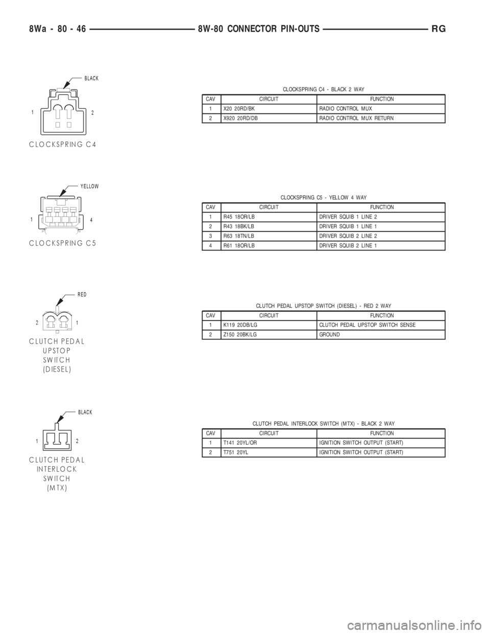
CLOCKSPRING C4 - BLACK 2 WAY
CAV CIRCUIT FUNCTION
1 X20 20RD/BK RADIO CONTROL MUX
2 X920 20RD/DB RADIO CONTROL MUX RETURN
CLOCKSPRING C5 - YELLOW 4 WAY
CAV CIRCUIT FUNCTION
1 R45 18OR/LB DRIVER SQUIB 1 LINE 2
2 R43 18BK/LB DRIVER SQUIB 1 LINE 1
3 R63 18TN/LB DRIVER SQUIB 2 LINE 2
4 R61 18OR/LB DRIVER SQUIB 2 LINE 1
CLUTCH PEDAL UPSTOP SWITCH (DIESEL) - RED 2 WAY
CAV CIRCUIT FUNCTION
1 K119 20DB/LG CLUTCH PEDAL UPSTOP SWITCH SENSE
2 Z150 20BK/LG GROUND
CLUTCH PEDAL INTERLOCK SWITCH (MTX) - BLACK 2 WAY
CAV CIRCUIT FUNCTION
1 T141 20YL/OR IGNITION SWITCH OUTPUT (START)
2 T751 20YL IGNITION SWITCH OUTPUT (START)
8Wa - 80 - 46 8W-80 CONNECTOR PIN-OUTSRG
Page 2544 of 4284
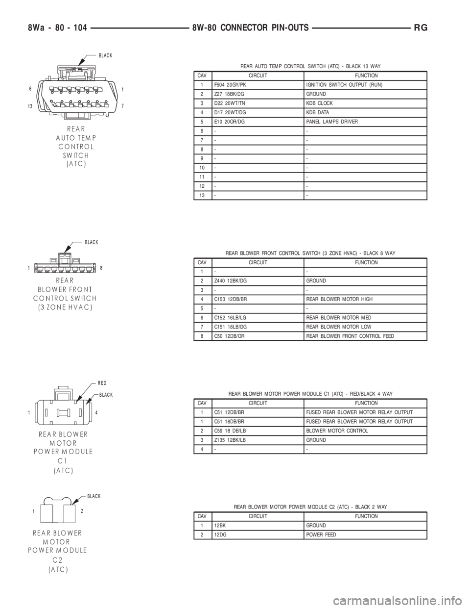
REAR AUTO TEMP CONTROL SWITCH (ATC) - BLACK 13 WAY
CAV CIRCUIT FUNCTION
1 F504 20GY/PK IGNITION SWITCH OUTPUT (RUN)
2 Z27 18BK/DG GROUND
3 D22 20WT/TN KDB CLOCK
4 D17 20WT/DG KDB DATA
5 E10 20OR/DG PANEL LAMPS DRIVER
6- -
7- -
8- -
9- -
10 - -
11 - -
12 - -
13 - -
REAR BLOWER FRONT CONTROL SWITCH (3 ZONE HVAC) - BLACK 8 WAY
CAV CIRCUIT FUNCTION
1- -
2 Z440 12BK/DG GROUND
3- -
4 C153 12DB/BR REAR BLOWER MOTOR HIGH
5- -
6 C152 16LB/LG REAR BLOWER MOTOR MED
7 C151 18LB/DG REAR BLOWER MOTOR LOW
8 C50 12DB/OR REAR BLOWER FRONT CONTROL FEED
REAR BLOWER MOTOR POWER MODULE C1 (ATC) - RED/BLACK 4 WAY
CAV CIRCUIT FUNCTION
1 C51 12DB/BR FUSED REAR BLOWER MOTOR RELAY OUTPUT
1 C51 18DB/BR FUSED REAR BLOWER MOTOR RELAY OUTPUT
2 C59 18 DB/LB BLOWER MOTOR CONTROL
3 Z135 12BK/LB GROUND
4- -
REAR BLOWER MOTOR POWER MODULE C2 (ATC) - BLACK 2 WAY
CAV CIRCUIT FUNCTION
1 12BK GROUND
2 12DG POWER FEED
8Wa - 80 - 104 8W-80 CONNECTOR PIN-OUTSRG
Page 2565 of 4284
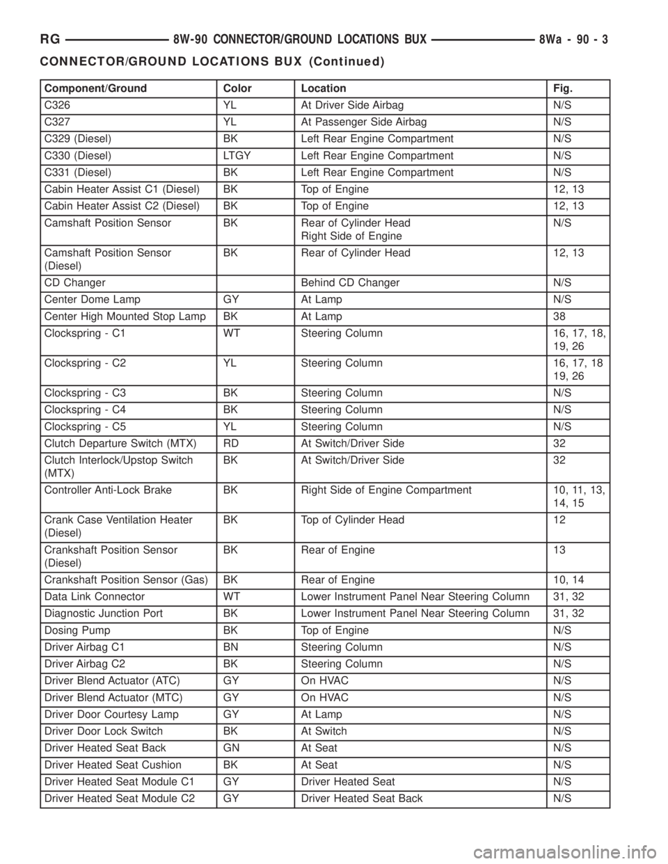
Component/Ground Color Location Fig.
C326 YL At Driver Side Airbag N/S
C327 YL At Passenger Side Airbag N/S
C329 (Diesel) BK Left Rear Engine Compartment N/S
C330 (Diesel) LTGY Left Rear Engine Compartment N/S
C331 (Diesel) BK Left Rear Engine Compartment N/S
Cabin Heater Assist C1 (Diesel) BK Top of Engine 12, 13
Cabin Heater Assist C2 (Diesel) BK Top of Engine 12, 13
Camshaft Position Sensor BK Rear of Cylinder Head
Right Side of EngineN/S
Camshaft Position Sensor
(Diesel)BK Rear of Cylinder Head 12, 13
CD Changer Behind CD Changer N/S
Center Dome Lamp GY At Lamp N/S
Center High Mounted Stop Lamp BK At Lamp 38
Clockspring - C1 WT Steering Column 16, 17, 18,
19, 26
Clockspring - C2 YL Steering Column 16, 17, 18
19, 26
Clockspring - C3 BK Steering Column N/S
Clockspring - C4 BK Steering Column N/S
Clockspring - C5 YL Steering Column N/S
Clutch Departure Switch (MTX) RD At Switch/Driver Side 32
Clutch Interlock/Upstop Switch
(MTX)BK At Switch/Driver Side 32
Controller Anti-Lock Brake BK Right Side of Engine Compartment 10, 11, 13,
14, 15
Crank Case Ventilation Heater
(Diesel)BK Top of Cylinder Head 12
Crankshaft Position Sensor
(Diesel)BK Rear of Engine 13
Crankshaft Position Sensor (Gas) BK Rear of Engine 10, 14
Data Link Connector WT Lower Instrument Panel Near Steering Column 31, 32
Diagnostic Junction Port BK Lower Instrument Panel Near Steering Column 31, 32
Dosing Pump BK Top of Engine N/S
Driver Airbag C1 BN Steering Column N/S
Driver Airbag C2 BK Steering Column N/S
Driver Blend Actuator (ATC) GY On HVAC N/S
Driver Blend Actuator (MTC) GY On HVAC N/S
Driver Door Courtesy Lamp GY At Lamp N/S
Driver Door Lock Switch BK At Switch N/S
Driver Heated Seat Back GN At Seat N/S
Driver Heated Seat Cushion BK At Seat N/S
Driver Heated Seat Module C1 GY Driver Heated Seat N/S
Driver Heated Seat Module C2 GY Driver Heated Seat Back N/S
RG8W-90 CONNECTOR/GROUND LOCATIONS BUX8Wa-90-3
CONNECTOR/GROUND LOCATIONS BUX (Continued)
Page 2676 of 4284
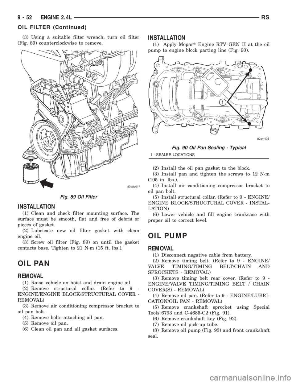
(3) Using a suitable filter wrench, turn oil filter
(Fig. 89) counterclockwise to remove.
INSTALLATION
(1) Clean and check filter mounting surface. The
surface must be smooth, flat and free of debris or
pieces of gasket.
(2) Lubricate new oil filter gasket with clean
engine oil.
(3) Screw oil filter (Fig. 89) on until the gasket
contacts base. Tighten to 21 N´m (15 ft. lbs.).
OIL PAN
REMOVAL
(1) Raise vehicle on hoist and drain engine oil.
(2) Remove structural collar. (Refer to 9 -
ENGINE/ENGINE BLOCK/STRUCTURAL COVER -
REMOVAL)
(3) Remove air conditioning compressor bracket to
oil pan bolt.
(4) Remove bolts attaching oil pan.
(5) Remove oil pan.
(6) Clean oil pan and all gasket surfaces.
INSTALLATION
(1) Apply MopartEngine RTV GEN II at the oil
pump to engine block parting line (Fig. 90).
(2) Install the oil pan gasket to the block.
(3) Install pan and tighten the screws to 12 N´m
(105 in. lbs.).
(4) Install air conditioning compressor bracket to
oil pan bolt.
(5) Install structural collar. (Refer to 9 - ENGINE/
ENGINE BLOCK/STRUCTURAL COVER - INSTAL-
LATION)
(6) Lower vehicle and fill engine crankcase with
proper oil to correct level.
OIL PUMP
REMOVAL
(1) Disconnect negative cable from battery.
(2) Remove timing belt. (Refer to 9 - ENGINE/
VALVE TIMING/TIMING BELT/CHAIN AND
SPROCKETS - REMOVAL)
(3) Remove timing belt rear cover. (Refer to 9 -
ENGINE/VALVE TIMING/TIMING BELT / CHAIN
COVER(S) - REMOVAL)
(4) Remove oil pan. (Refer to 9 - ENGINE/LUBRI-
CATION/OIL PAN - REMOVAL)
(5) Remove crankshaft sprocket using Special
Tools 6793 and C-4685-C2 (Fig. 91).
(6) Remove crankshaft key (Fig. 92).
(7) Remove oil pick-up tube.
(8) Remove oil pump (Fig. 93) and front crankshaft
seal.
Fig. 89 Oil Filter
Fig. 90 Oil Pan Sealing - Typical
1 - SEALER LOCATIONS
9 - 52 ENGINE 2.4LRS
OIL FILTER (Continued)
Page 2686 of 4284
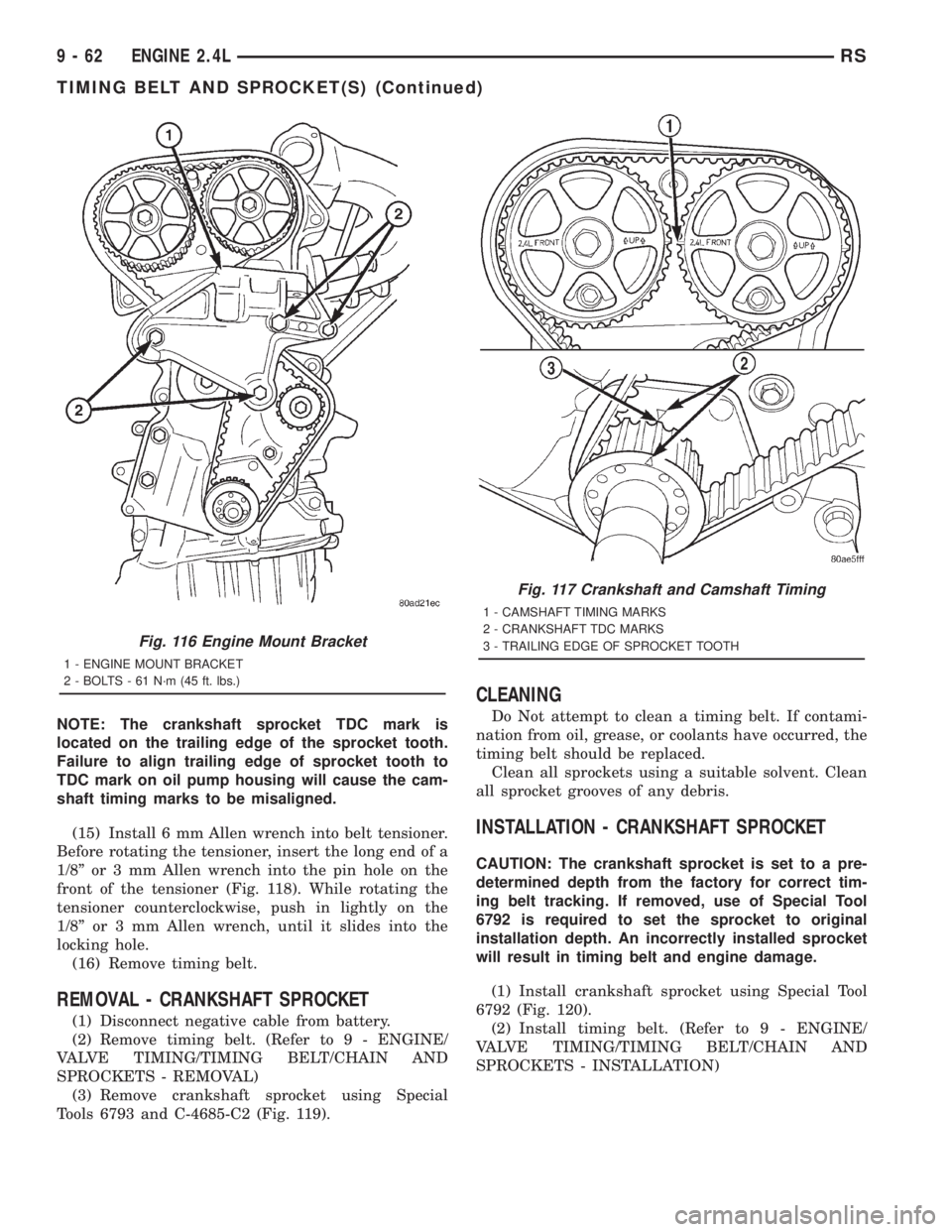
NOTE: The crankshaft sprocket TDC mark is
located on the trailing edge of the sprocket tooth.
Failure to align trailing edge of sprocket tooth to
TDC mark on oil pump housing will cause the cam-
shaft timing marks to be misaligned.
(15) Install 6 mm Allen wrench into belt tensioner.
Before rotating the tensioner, insert the long end of a
1/8º or 3 mm Allen wrench into the pin hole on the
front of the tensioner (Fig. 118). While rotating the
tensioner counterclockwise, push in lightly on the
1/8º or 3 mm Allen wrench, until it slides into the
locking hole.
(16) Remove timing belt.
REMOVAL - CRANKSHAFT SPROCKET
(1) Disconnect negative cable from battery.
(2) Remove timing belt. (Refer to 9 - ENGINE/
VALVE TIMING/TIMING BELT/CHAIN AND
SPROCKETS - REMOVAL)
(3) Remove crankshaft sprocket using Special
Tools 6793 and C-4685-C2 (Fig. 119).
CLEANING
Do Not attempt to clean a timing belt. If contami-
nation from oil, grease, or coolants have occurred, the
timing belt should be replaced.
Clean all sprockets using a suitable solvent. Clean
all sprocket grooves of any debris.
INSTALLATION - CRANKSHAFT SPROCKET
CAUTION: The crankshaft sprocket is set to a pre-
determined depth from the factory for correct tim-
ing belt tracking. If removed, use of Special Tool
6792 is required to set the sprocket to original
installation depth. An incorrectly installed sprocket
will result in timing belt and engine damage.
(1) Install crankshaft sprocket using Special Tool
6792 (Fig. 120).
(2) Install timing belt. (Refer to 9 - ENGINE/
VALVE TIMING/TIMING BELT/CHAIN AND
SPROCKETS - INSTALLATION)
Fig. 116 Engine Mount Bracket
1 - ENGINE MOUNT BRACKET
2 - BOLTS - 61 N´m (45 ft. lbs.)
Fig. 117 Crankshaft and Camshaft Timing
1 - CAMSHAFT TIMING MARKS
2 - CRANKSHAFT TDC MARKS
3 - TRAILING EDGE OF SPROCKET TOOTH
9 - 62 ENGINE 2.4LRS
TIMING BELT AND SPROCKET(S) (Continued)
Page 2687 of 4284
INSTALLATION - TIMING BELT
CAUTION: The crankshaft sprocket is set to a pre-
determined depth from the factory for correct tim-
ing belt tracking. If removed, use of Special Tool
6792 is required to set the sprocket to original
installation depth. An incorrectly installed sprocket
will result in timing belt and engine damage.
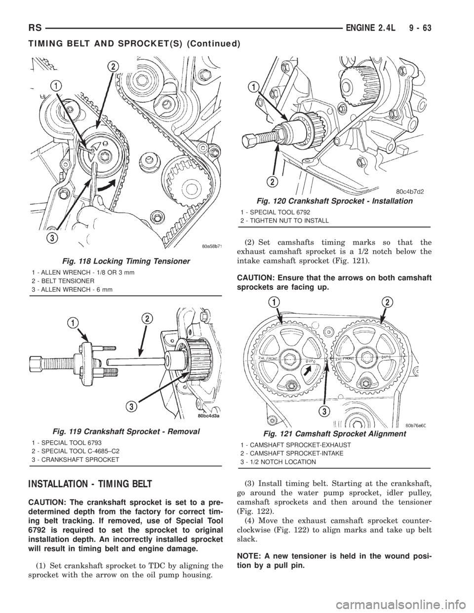
(1) Set crankshaft sprocket to TDC by aligning the
sprocket with the arrow on the oil pump housing.(2) Set camshafts timing marks so that the
exhaust camshaft sprocket is a 1/2 notch below the
intake camshaft sprocket (Fig. 121).
CAUTION: Ensure that the arrows on both camshaft
sprockets are facing up.
(3) Install timing belt. Starting at the crankshaft,
go around the water pump sprocket, idler pulley,
camshaft sprockets and then around the tensioner
(Fig. 122).
(4) Move the exhaust camshaft sprocket counter-
clockwise (Fig. 122) to align marks and take up belt
slack.
NOTE: A new tensioner is held in the wound posi-
tion by a pull pin.
Fig. 118 Locking Timing Tensioner
1 - ALLEN WRENCH - 1/8 OR 3 mm
2 - BELT TENSIONER
3 - ALLEN WRENCH-6mm
Fig. 119 Crankshaft Sprocket - Removal
1 - SPECIAL TOOL 6793
2 - SPECIAL TOOL C-4685±C2
3 - CRANKSHAFT SPROCKET
Fig. 120 Crankshaft Sprocket - Installation
1 - SPECIAL TOOL 6792
2 - TIGHTEN NUT TO INSTALL
Fig. 121 Camshaft Sprocket Alignment
1 - CAMSHAFT SPROCKET-EXHAUST
2 - CAMSHAFT SPROCKET-INTAKE
3 - 1/2 NOTCH LOCATION
RSENGINE 2.4L9-63
TIMING BELT AND SPROCKET(S) (Continued)
Page 2693 of 4284
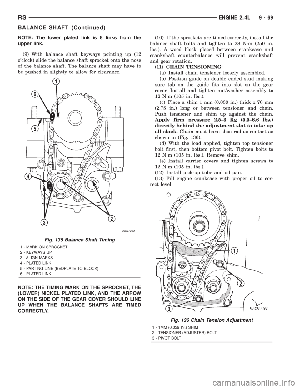
NOTE: The lower plated link is 8 links from the
upper link.
(9) With balance shaft keyways pointing up (12
o'clock) slide the balance shaft sprocket onto the nose
of the balance shaft. The balance shaft may have to
be pushed in slightly to allow for clearance.
NOTE: THE TIMING MARK ON THE SPROCKET, THE
(LOWER) NICKEL PLATED LINK, AND THE ARROW
ON THE SIDE OF THE GEAR COVER SHOULD LINE
UP WHEN THE BALANCE SHAFTS ARE TIMED
CORRECTLY.(10) If the sprockets are timed correctly, install the
balance shaft bolts and tighten to 28 N´m (250 in.
lbs.). A wood block placed between crankcase and
crankshaft counterbalance will prevent crankshaft
and gear rotation.
(11)CHAIN TENSIONING:
(a) Install chain tensioner loosely assembled.
(b) Position guide on double ended stud making
sure tab on the guide fits into slot on the gear
cover. Install and tighten nut/washer assembly to
12 N´m (105 in. lbs.).
(c) Place a shim 1 mm (0.039 in.) thick x 70 mm
(2.75 in.) long or between tensioner and chain.
Push tensioner and shim up against the chain.
Apply firm pressure 2.5±3 Kg (5.5±6.6 lbs.)
directly behind the adjustment slot to take up
all slack.Chain must have shoe radius contact as
shown in (Fig. 136).
(d) With the load applied, tighten top tensioner
bolt first, then bottom pivot bolt. Tighten bolts to
12 N´m (105 in. lbs.). Remove shim.
(e) Install carrier covers and tighten screws to
12 N´m (105 in. lbs.).
(12) Install pick-up tube and oil pan.
(13) Fill engine crankcase with proper oil to cor-
rect level.
Fig. 135 Balance Shaft Timing
1 - MARK ON SPROCKET
2 - KEYWAYS UP
3 - ALIGN MARKS
4 - PLATED LINK
5 - PARTING LINE (BEDPLATE TO BLOCK)
6 - PLATED LINK
Fig. 136 Chain Tension Adjustment
1 - 1MM (0.039 IN.) SHIM
2 - TENSIONER (ADJUSTER) BOLT
3 - PIVOT BOLT
RSENGINE 2.4L9-69
BALANCE SHAFT (Continued)
Page 2727 of 4284
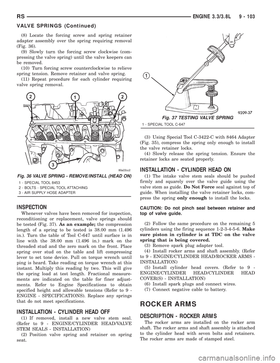
(8) Locate the forcing screw and spring retainer
adapter assembly over the spring requiring removal
(Fig. 36).
(9) Slowly turn the forcing screw clockwise (com-
pressing the valve spring) until the valve keepers can
be removed.
(10) Turn forcing screw counterclockwise to relieve
spring tension. Remove retainer and valve spring.
(11) Repeat procedure for each cylinder requiring
valve spring removal.
INSPECTION
Whenever valves have been removed for inspection,
reconditioning or replacement, valve springs should
be tested (Fig. 37).As an example;the compression
length of a spring to be tested is 38.00 mm (1.496
in.). Turn the table of Tool C-647 until surface is in
line with the 38.00 mm (1.496 in.) mark on the
threaded stud and the zero mark on the front. Place
spring over stud on the table and lift compressing
lever to set tone device. Pull on torque wrench until
ping is heard. Take reading on torque wrench at this
instant. Multiply this reading by two. This will give
the spring load at test length. Fractional measure-
ments are indicated on the table for finer adjust-
ments. Refer to Engine Specifications to obtain
specified height and allowable tensions (Refer to 9 -
ENGINE - SPECIFICATIONS). Replace any springs
that do not meet specifications.
INSTALLATION - CYLINDER HEAD OFF
(1) If removed, install a new valve stem seal.
(Refer to 9 - ENGINE/CYLINDER HEAD/VALVE
STEM SEALS - INSTALLATION)
(2) Position valve spring and retainer on spring
seat.(3) Using Special Tool C-3422-C with 8464 Adapter
(Fig. 35), compress the spring only enough to install
the valve retainer locks.
(4) Slowly release the spring tension. Ensure the
retainer locks are seated properly.
INSTALLATION - CYLINDER HEAD ON
(1)The intake valve stem seals should be pushed
firmly and squarely over the valve guide using the
valve stem as guide.Do Not Force
seal against top of
guide. When installing the valve retainer locks, com-
press the springonly enoughto install the locks.
CAUTION: Do not pinch seal between retainer and
top of valve guide.
(2) Follow the same procedure on the remaining 5
cylinders using the firing sequence 1-2-3-4-5-6.Make
sure piston in cylinder is at TDC on the valve
spring that is being covered.
(3) Remove spark plug adapter tool.
(4) Install rocker arms and shaft assembly. (Refer
to 9 - ENGINE/CYLINDER HEAD/ROCKER ARMS -
INSTALLATION)
(5) Install cylinder head covers. (Refer to 9 -
ENGINE/CYLINDER HEAD/CYLINDER HEAD
COVER(S) - INSTALLATION)
(6) Install spark plugs and connect wires.
(7) Connect negative cable to battery.
ROCKER ARMS
DESCRIPTION - ROCKER ARMS
The rocker arms are installed on the rocker arm
shaft. The rocker arms and shaft assembly is attached
to the cylinder head with seven bolts and retainers.
The rocker arms are made of stamped steel.
Fig. 36 VALVE SPRING - REMOVE/INSTALL (HEAD ON)
1 - SPECIAL TOOL 8453
2 - BOLTS - SPECIAL TOOL ATTACHING
3 - AIR SUPPLY HOSE ADAPTER
Fig. 37 TESTING VALVE SPRING
1 - SPECIAL TOOL C-647
RSENGINE 3.3/3.8L9 - 103
VALVE SPRINGS (Continued)