tow CHRYSLER VOYAGER 2001 Service Manual
[x] Cancel search | Manufacturer: CHRYSLER, Model Year: 2001, Model line: VOYAGER, Model: CHRYSLER VOYAGER 2001Pages: 4284, PDF Size: 83.53 MB
Page 2927 of 4284
NOTE: Power steering pump maximum relief pres-
sure is 9,653 to 10,342 kPa (1,400 to 1,500 psi.).
(9) Close analyzer valve fully three times and
record highest pressure indicated each time. All three
readings must be above specifications and within 345
kPa (50 psi) of each other.
²If power steering pump pressures are above
specifications, but not within 345 kPa (50 psi) of each
other, replace pump.
²If power steering pump pressures are within 345
kPa (50 psi) of each other, but are below specifica-
tions, replace pump.
CAUTION: Do not force the pump to operate against
the stops for more than 2 to 4 seconds at a time
because, pump damage will result.
(10) Completely open the valve on the Power
Steering Analyzer. Turn the steering wheel to theextreme left until the stop in the steering gear is
met, then turn the steering wheel to the right until
the right stop is met. Record the highest indicated
pressure at each position. Compare the recorded
readings to the specifications. If the highest output
pressures are not the same against either stop, the
steering gear is leaking internally and must be
replaced.
DIAGNOSIS AND TESTING - STEERING
SYSTEM DIAGNOSIS CHARTS
NOTE: There are three diagnosis charts following
that cover POWER STEERING NOISE, STEERING
WHEEL FEEL, and POWER STEERING FLUID.
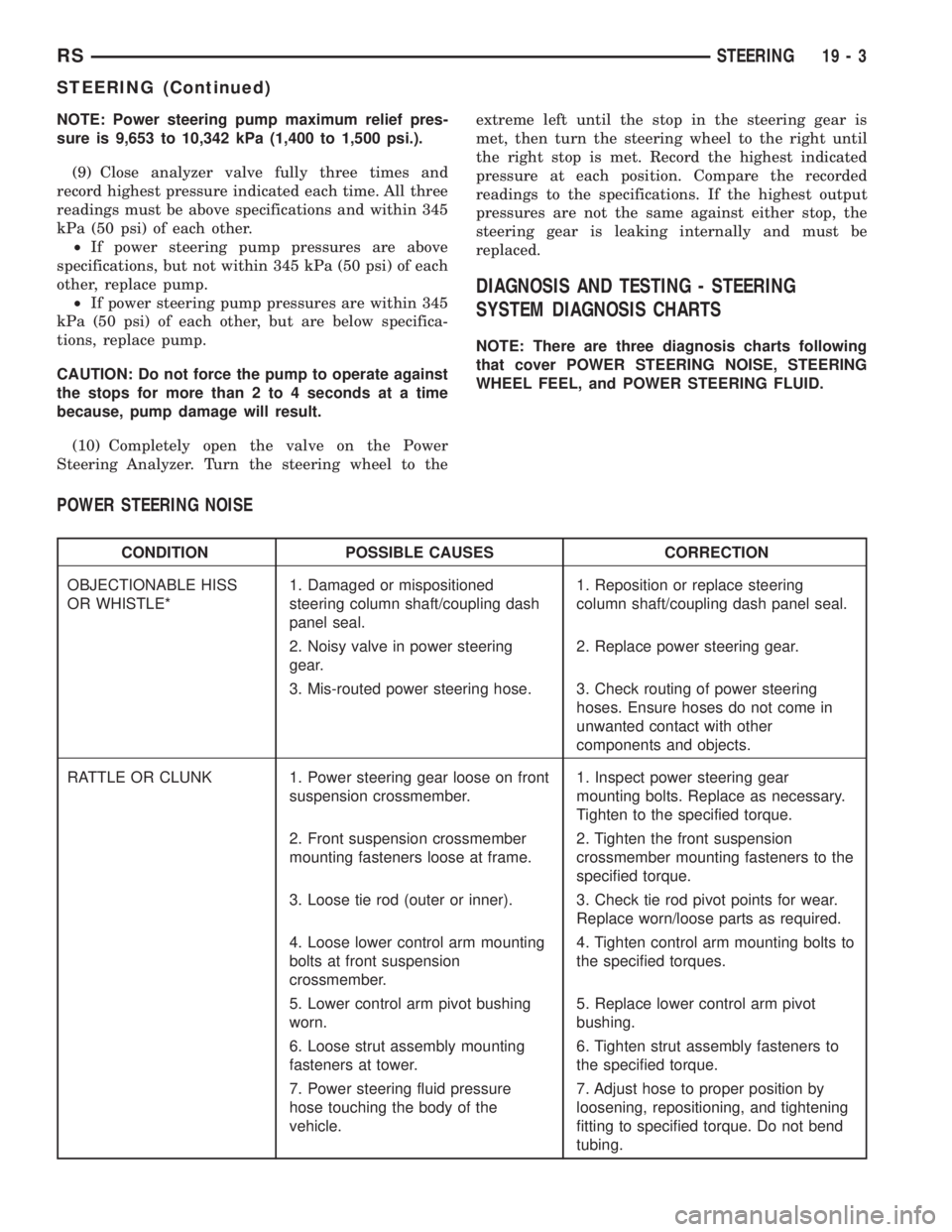
POWER STEERING NOISE
CONDITION POSSIBLE CAUSES CORRECTION
OBJECTIONABLE HISS
OR WHISTLE*1. Damaged or mispositioned
steering column shaft/coupling dash
panel seal.1. Reposition or replace steering
column shaft/coupling dash panel seal.
2. Noisy valve in power steering
gear.2. Replace power steering gear.
3. Mis-routed power steering hose. 3. Check routing of power steering
hoses. Ensure hoses do not come in
unwanted contact with other
components and objects.
RATTLE OR CLUNK 1. Power steering gear loose on front
suspension crossmember.1. Inspect power steering gear
mounting bolts. Replace as necessary.
Tighten to the specified torque.
2. Front suspension crossmember
mounting fasteners loose at frame.2. Tighten the front suspension
crossmember mounting fasteners to the
specified torque.
3. Loose tie rod (outer or inner). 3. Check tie rod pivot points for wear.
Replace worn/loose parts as required.
4. Loose lower control arm mounting
bolts at front suspension
crossmember.4. Tighten control arm mounting bolts to
the specified torques.
5. Lower control arm pivot bushing
worn.5. Replace lower control arm pivot
bushing.
6. Loose strut assembly mounting
fasteners at tower.6. Tighten strut assembly fasteners to
the specified torque.
7. Power steering fluid pressure
hose touching the body of the
vehicle.7. Adjust hose to proper position by
loosening, repositioning, and tightening
fitting to specified torque. Do not bend
tubing.
RSSTEERING19-3
STEERING (Continued)
Page 2978 of 4284
INSTALLATION
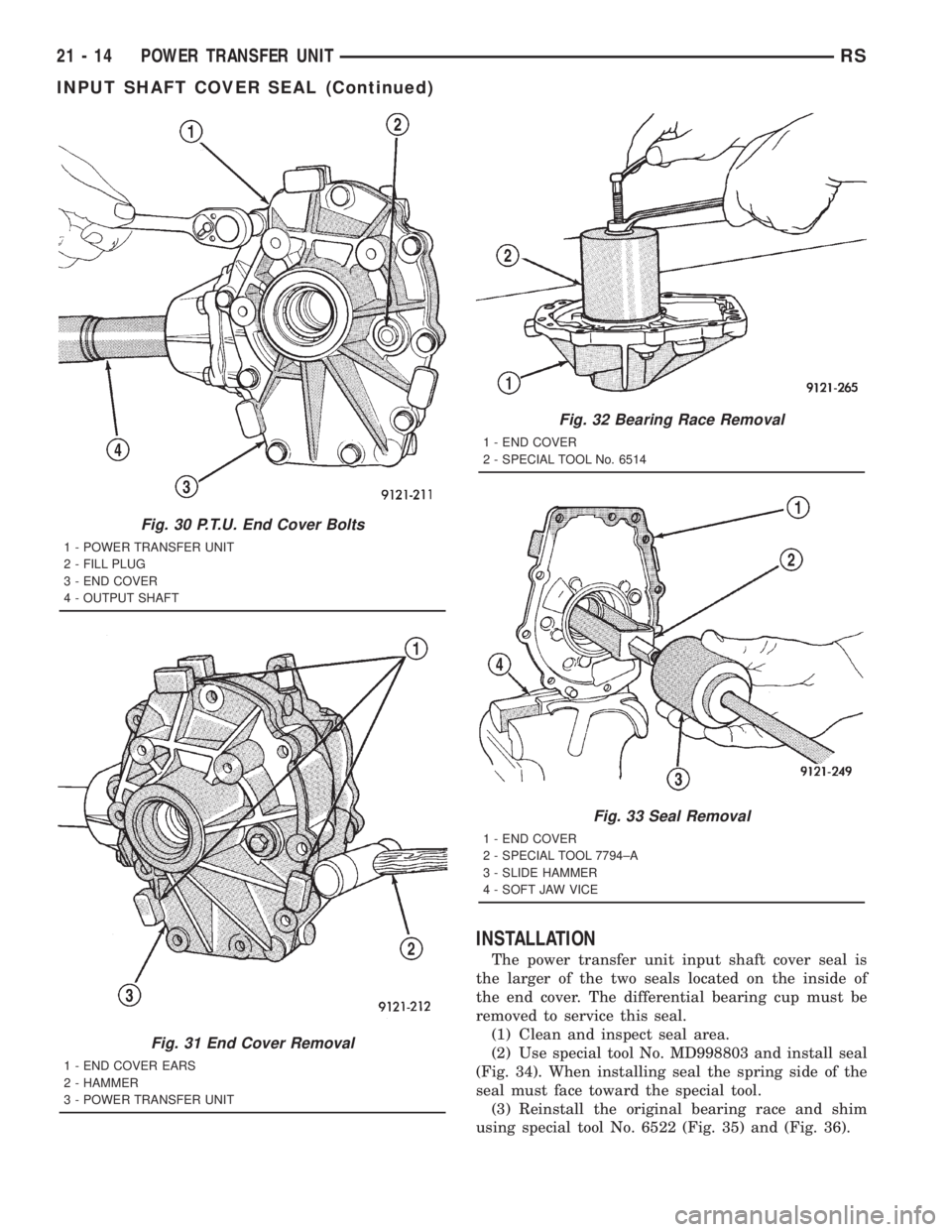
The power transfer unit input shaft cover seal is
the larger of the two seals located on the inside of
the end cover. The differential bearing cup must be
removed to service this seal.
(1) Clean and inspect seal area.
(2) Use special tool No. MD998803 and install seal
(Fig. 34). When installing seal the spring side of the
seal must face toward the special tool.
(3) Reinstall the original bearing race and shim
using special tool No. 6522 (Fig. 35) and (Fig. 36).
Fig. 30 P.T.U. End Cover Bolts
1 - POWER TRANSFER UNIT
2 - FILL PLUG
3 - END COVER
4 - OUTPUT SHAFT
Fig. 31 End Cover Removal
1 - END COVER EARS
2 - HAMMER
3 - POWER TRANSFER UNIT
Fig. 32 Bearing Race Removal
1 - END COVER
2 - SPECIAL TOOL No. 6514
Fig. 33 Seal Removal
1 - END COVER
2 - SPECIAL TOOL 7794±A
3 - SLIDE HAMMER
4 - SOFT JAW VICE
21 - 14 POWER TRANSFER UNITRS
INPUT SHAFT COVER SEAL (Continued)
Page 2982 of 4284
INSTALLATION
The Power Transfer Unit must be removed from
the vehicle to service this seal. Refer to Power Trans-
fer Unit Removal in this section for procedures.(1) Clean and inspect seal area.
(2) Lay housing on bench and install new seal with
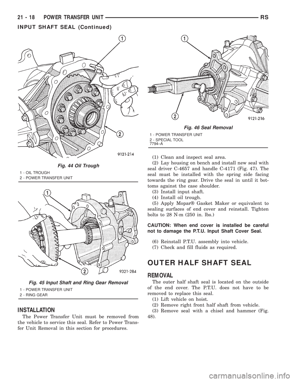
seal driver C-4657 and handle C-4171 (Fig. 47). The
seal must be installed with the spring side facing
towards the ring gear. Drive the seal in until it bot-
toms against the case shoulder.
(3) Install input shaft.
(4) Install oil trough.
(5) Apply Moparž Gasket Maker or equivalent to
sealing surfaces of end cover and reinstall. Tighten
bolts to 28 N´m (250 in. lbs.)
CAUTION: When end cover is installed be careful
not to damage the P.T.U. Input Shaft Cover Seal.
(6) Reinstall P.T.U. assembly into vehicle.
(7) Check and fill fluids as required.
OUTER HALF SHAFT SEAL
REMOVAL
The outer half shaft seal is located on the outside
of the end cover. The P.T.U. does not have to be
removed to replace this seal.
(1) Lift vehicle on hoist.
(2) Remove right front half shaft from vehicle.
(3) Remove seal with a chisel and hammer (Fig.
48).
Fig. 44 Oil Trough
1 - OIL TROUGH
2 - POWER TRANSFER UNIT
Fig. 45 Input Shaft and Ring Gear Removal
1 - POWER TRANSFER UNIT
2 - RING GEAR
Fig. 46 Seal Removal
1 - POWER TRANSFER UNIT
2 - SPECIAL TOOL
7794±A
21 - 18 POWER TRANSFER UNITRS
INPUT SHAFT SEAL (Continued)
Page 3075 of 4284
CLEANING
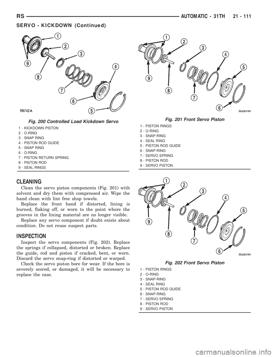
Clean the servo piston components (Fig. 201) with
solvent and dry them with compressed air. Wipe the
band clean with lint free shop towels.
Replace the front band if distorted, lining is
burned, flaking off, or worn to the point where the
grooves in the lining material are no longer visible.
Replace any servo component if doubt exists about
condition. Do not reuse suspect parts.
INSPECTION
Inspect the servo components (Fig. 202). Replace
the springs if collapsed, distorted or broken. Replace
the guide, rod and piston if cracked, bent, or worn.
Discard the servo snap-ring if distorted or warped.
Check the servo piston bore for wear. If the bore is
severely scored, or damaged, it will be necessary to
replace the case.
Fig. 200 Controlled Load Kickdown Servo
1 - KICKDOWN PISTON
2 - O-RING
3 - SNAP RING
4 - PISTON ROD GUIDE
5 - SNAP RING
6 - O-RING
7 - PISTON RETURN SPRING
8 - PISTON ROD
9 - SEAL RINGS
Fig. 201 Front Servo Piston
1 - PISTON RINGS
2 - O-RING
3 - SNAP-RING
4 - SEAL RING
5 - PISTON ROD GUIDE
6 - SNAP-RING
7 - SERVO SPRING
8 - PISTON ROD
9 - SERVO PISTON
Fig. 202 Front Servo Piston
1 - PISTON RINGS
2 - O-RING
3 - SNAP-RING
4 - SEAL RING
5 - PISTON ROD GUIDE
6 - SNAP-RING
7 - SERVO SPRING
8 - PISTON ROD
9 - SERVO PISTON
RSAUTOMATIC - 31TH21 - 111
SERVO - KICKDOWN (Continued)
Page 3079 of 4284
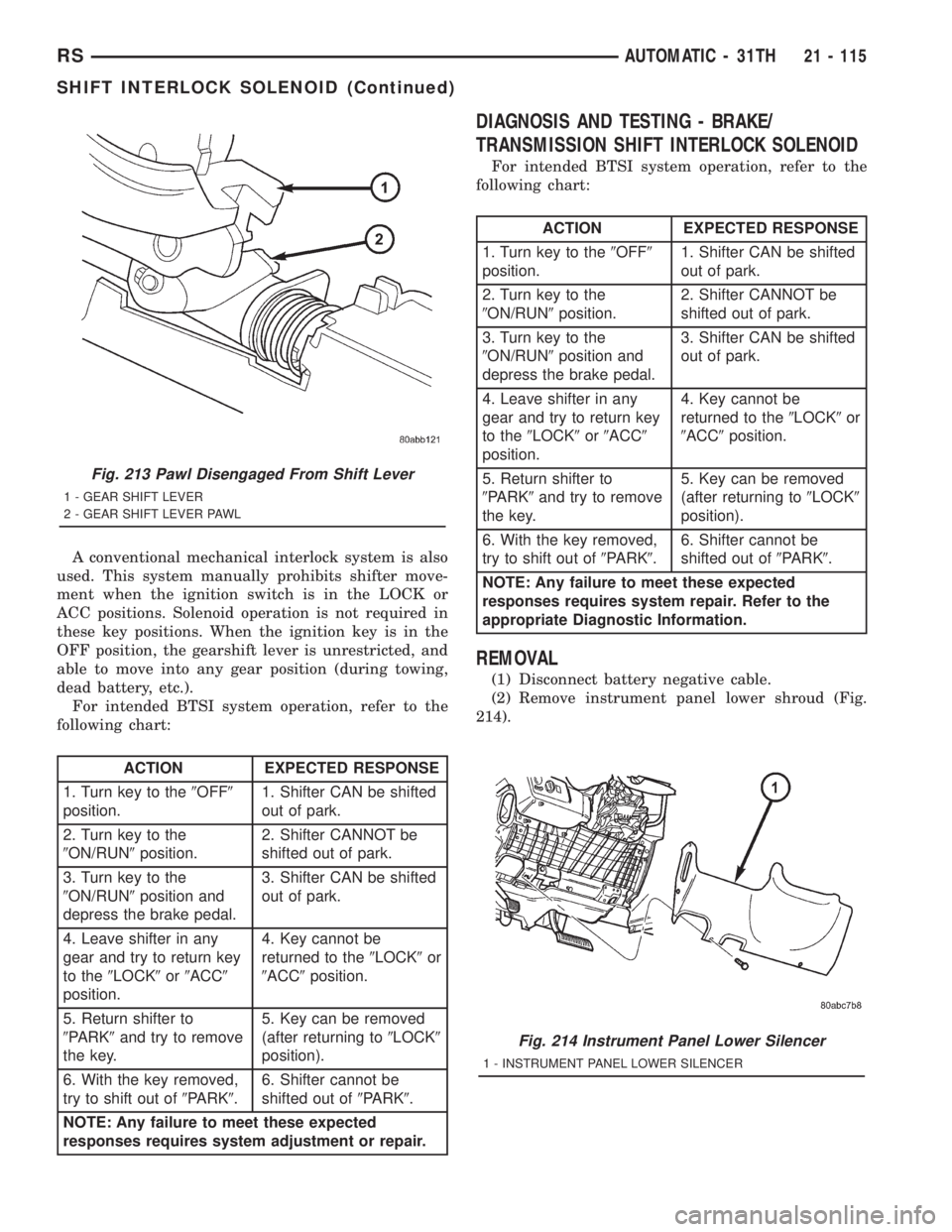
A conventional mechanical interlock system is also
used. This system manually prohibits shifter move-
ment when the ignition switch is in the LOCK or
ACC positions. Solenoid operation is not required in
these key positions. When the ignition key is in the
OFF position, the gearshift lever is unrestricted, and
able to move into any gear position (during towing,
dead battery, etc.).
For intended BTSI system operation, refer to the
following chart:
ACTION EXPECTED RESPONSE
1. Turn key to the9OFF9
position.1. Shifter CAN be shifted
out of park.
2. Turn key to the
9ON/RUN9position.2. Shifter CANNOT be
shifted out of park.
3. Turn key to the
9ON/RUN9position and
depress the brake pedal.3. Shifter CAN be shifted
out of park.
4. Leave shifter in any
gear and try to return key
to the9LOCK9or9ACC9
position.4. Key cannot be
returned to the9LOCK9or
9ACC9position.
5. Return shifter to
9PARK9and try to remove
the key.5. Key can be removed
(after returning to9LOCK9
position).
6. With the key removed,
try to shift out of9PARK9.6. Shifter cannot be
shifted out of9PARK9.
NOTE: Any failure to meet these expected
responses requires system adjustment or repair.
DIAGNOSIS AND TESTING - BRAKE/
TRANSMISSION SHIFT INTERLOCK SOLENOID
For intended BTSI system operation, refer to the
following chart:
ACTION EXPECTED RESPONSE
1. Turn key to the9OFF9
position.1. Shifter CAN be shifted
out of park.
2. Turn key to the
9ON/RUN9position.2. Shifter CANNOT be
shifted out of park.
3. Turn key to the
9ON/RUN9position and
depress the brake pedal.3. Shifter CAN be shifted
out of park.
4. Leave shifter in any
gear and try to return key
to the9LOCK9or9ACC9
position.4. Key cannot be
returned to the9LOCK9or
9ACC9position.
5. Return shifter to
9PARK9and try to remove
the key.5. Key can be removed
(after returning to9LOCK9
position).
6. With the key removed,
try to shift out of9PARK9.6. Shifter cannot be
shifted out of9PARK9.
NOTE: Any failure to meet these expected
responses requires system repair. Refer to the
appropriate Diagnostic Information.
REMOVAL
(1) Disconnect battery negative cable.
(2) Remove instrument panel lower shroud (Fig.
214).
Fig. 213 Pawl Disengaged From Shift Lever
1 - GEAR SHIFT LEVER
2 - GEAR SHIFT LEVER PAWL
Fig. 214 Instrument Panel Lower Silencer
1 - INSTRUMENT PANEL LOWER SILENCER
RSAUTOMATIC - 31TH21 - 115
SHIFT INTERLOCK SOLENOID (Continued)
Page 3087 of 4284
OPERATION
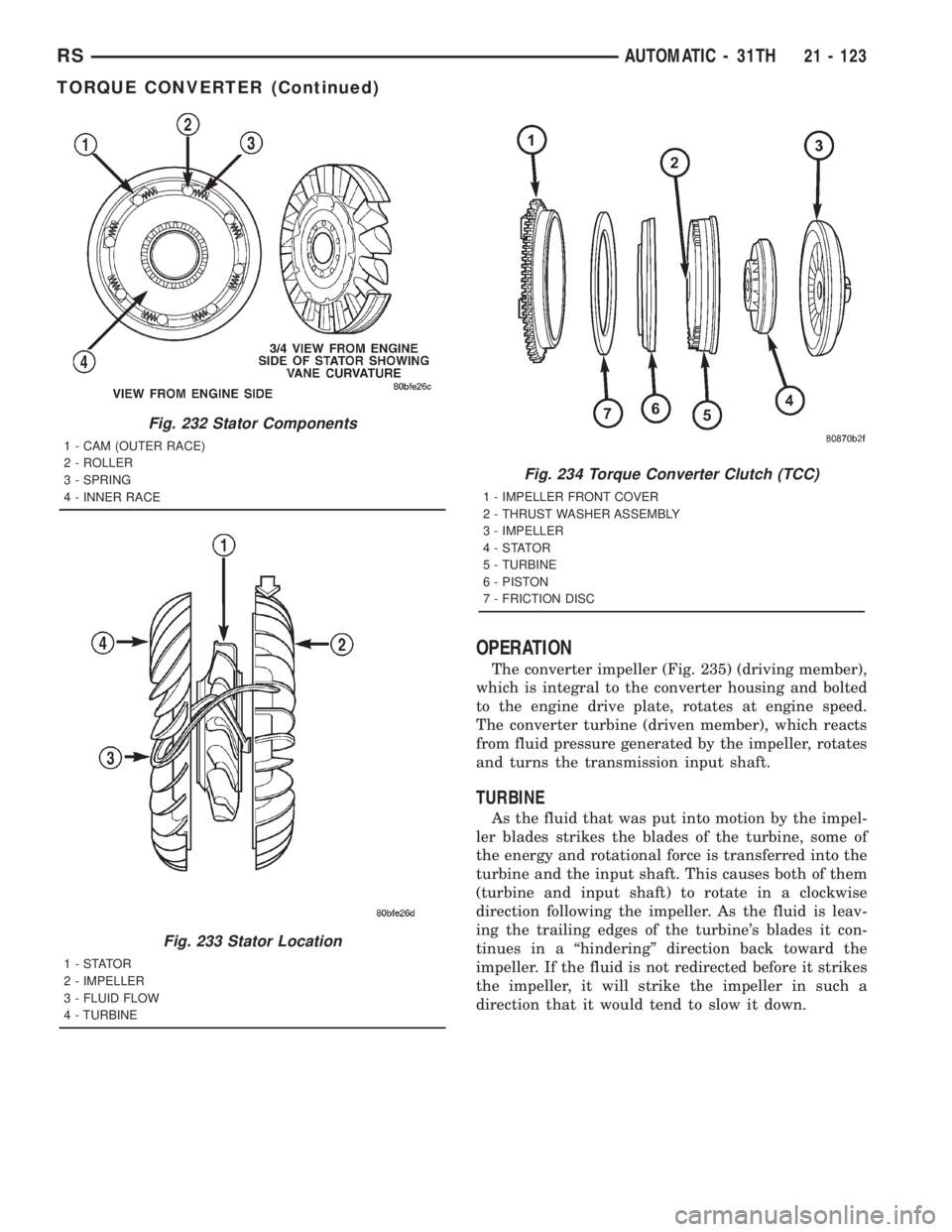
The converter impeller (Fig. 235) (driving member),
which is integral to the converter housing and bolted
to the engine drive plate, rotates at engine speed.
The converter turbine (driven member), which reacts
from fluid pressure generated by the impeller, rotates
and turns the transmission input shaft.
TURBINE
As the fluid that was put into motion by the impel-
ler blades strikes the blades of the turbine, some of
the energy and rotational force is transferred into the
turbine and the input shaft. This causes both of them
(turbine and input shaft) to rotate in a clockwise
direction following the impeller. As the fluid is leav-
ing the trailing edges of the turbine's blades it con-
tinues in a ªhinderingº direction back toward the
impeller. If the fluid is not redirected before it strikes
the impeller, it will strike the impeller in such a
direction that it would tend to slow it down.
Fig. 232 Stator Components
1 - CAM (OUTER RACE)
2 - ROLLER
3 - SPRING
4 - INNER RACE
Fig. 233 Stator Location
1-STATOR
2 - IMPELLER
3 - FLUID FLOW
4 - TURBINE
Fig. 234 Torque Converter Clutch (TCC)
1 - IMPELLER FRONT COVER
2 - THRUST WASHER ASSEMBLY
3 - IMPELLER
4-STATOR
5 - TURBINE
6 - PISTON
7 - FRICTION DISC
RSAUTOMATIC - 31TH21 - 123
TORQUE CONVERTER (Continued)
Page 3115 of 4284
CLEANING
Clean the valve body components in a parts clean-
ing solution only. Do not use gasoline, kerosene, or
any type of caustic solution. Dry the parts with com-
pressed air. Make sure all passages are clean and
free from obstructions.
NOTE: Do not use rags or shop towels to wipe off
valve body components. Lint from these materials
will adhere to the valve body components. Lint will
interfere with valve operation and may clog filters
and fluid passages.
Minor distortion of a valve body mating surface
may be corrected by smoothing the surface with cro-
cus cloth. The cloth should be in sheet form and be
positioned on a surface plate, sheet of plate glass, or
equally flat surface. However, if distortion is severeor any surfaces are heavily scored, the valve body
will have to be replaced.
CAUTION: Many of the valve body valves and plugs
are made of coated aluminum. Aluminum compo-
nents can be identified by the dark color of the spe-
cial coating applied to the surface (or by testing
with a magnet). DO NOT polish or sand aluminum
valves or plugs with any type of material, or under
any circumstances. This practice might damage the
special coating and cause the valves and plugs to
stick and bind.
Aluminum valves and plugs should not be sanded
or polished under any circumstances. However, minor
burrs or scratches on steel valves and plugs can be
removed with crocus cloth but do not round off the
valve or plug edges. Squareness of these edges is
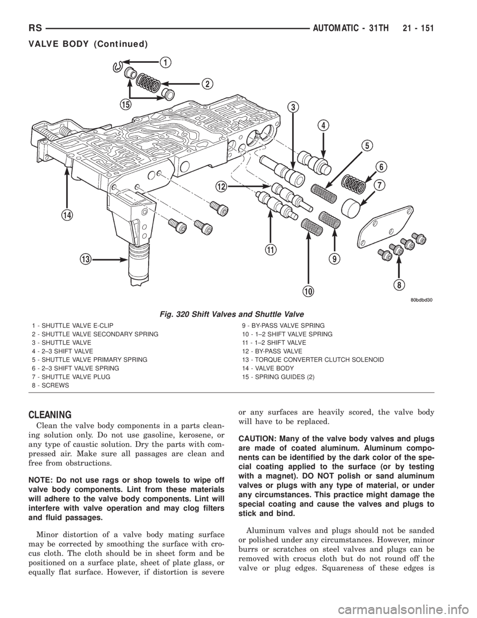
Fig. 320 Shift Valves and Shuttle Valve
1 - SHUTTLE VALVE E-CLIP
2 - SHUTTLE VALVE SECONDARY SPRING
3 - SHUTTLE VALVE
4 - 2±3 SHIFT VALVE
5 - SHUTTLE VALVE PRIMARY SPRING
6 - 2±3 SHIFT VALVE SPRING
7 - SHUTTLE VALVE PLUG
8 - SCREWS9 - BY-PASS VALVE SPRING
10 - 1±2 SHIFT VALVE SPRING
11 - 1±2 SHIFT VALVE
1 2 - B Y- PA S S VA LV E
13 - TORQUE CONVERTER CLUTCH SOLENOID
14 - VALVE BODY
15 - SPRING GUIDES (2)
RSAUTOMATIC - 31TH21 - 151
VALVE BODY (Continued)
Page 3169 of 4284

(55) Install cooler bypass valve with o-ring end
towards rear of case (Fig. 148).
(56) Install oil pump gasket (Fig. 149).(57) Install oil pump assembly (Fig. 150).
(58) Install oil pump-to-case bolts and torque to 27
N´m (20 ft. lbs.) (Fig. 151).
Fig. 148 Install Cooler Bypass Valve
1 - COOLER BYPASS VALVE
Fig. 149 Install Oil Pump Gasket
1 - PUMP GASKET
Fig. 150 Install Oil Pump
1 - OIL PUMP
2 - GASKET
Fig. 151 Install Pump-to-Case Bolts
1 - PUMP ATTACHING BOLTS
2 - PUMP HOUSING
RSAUTOMATIC - 41TE21 - 205
AUTOMATIC - 41TE (Continued)
Page 3229 of 4284
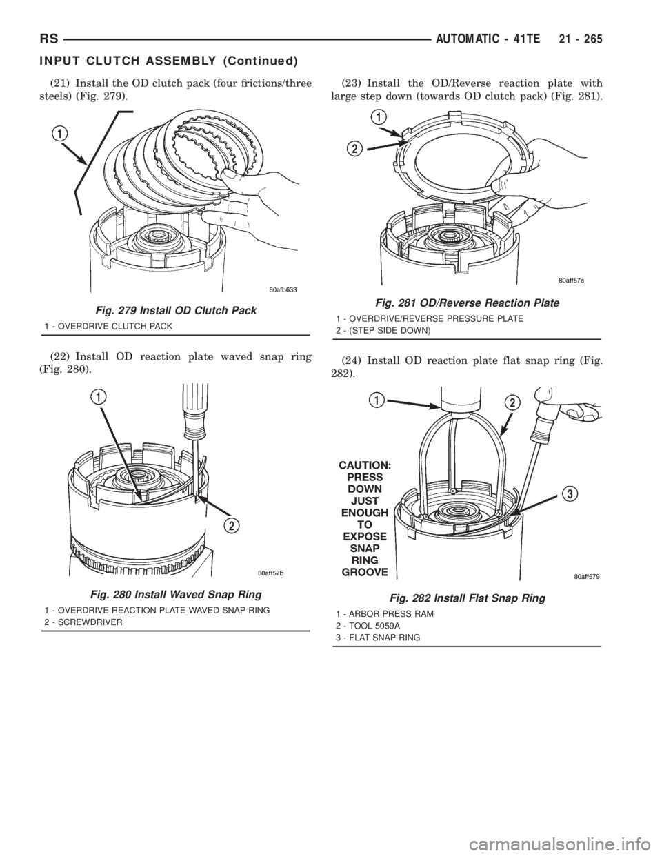
(21) Install the OD clutch pack (four frictions/three
steels) (Fig. 279).
(22) Install OD reaction plate waved snap ring
(Fig. 280).(23) Install the OD/Reverse reaction plate with
large step down (towards OD clutch pack) (Fig. 281).
(24) Install OD reaction plate flat snap ring (Fig.
282).
Fig. 279 Install OD Clutch Pack
1 - OVERDRIVE CLUTCH PACK
Fig. 280 Install Waved Snap Ring
1 - OVERDRIVE REACTION PLATE WAVED SNAP RING
2 - SCREWDRIVER
Fig. 281 OD/Reverse Reaction Plate
1 - OVERDRIVE/REVERSE PRESSURE PLATE
2 - (STEP SIDE DOWN)
Fig. 282 Install Flat Snap Ring
1 - ARBOR PRESS RAM
2 - TOOL 5059A
3 - FLAT SNAP RING
RSAUTOMATIC - 41TE21 - 265
INPUT CLUTCH ASSEMBLY (Continued)
Page 3230 of 4284
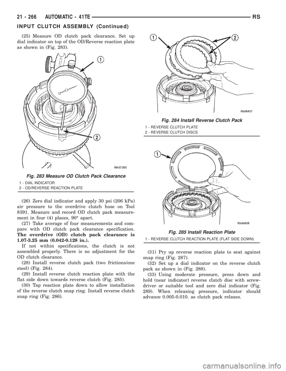
(25) Measure OD clutch pack clearance. Set up
dial indicator on top of the OD/Reverse reaction plate
as shown in (Fig. 283).
(26) Zero dial indicator and apply 30 psi (206 kPa)
air pressure to the overdrive clutch hose on Tool
8391. Measure and record OD clutch pack measure-
ment in four (4) places, 90É apart.
(27) Take average of four measurements and com-
pare with OD clutch pack clearance specification.
The overdrive (OD) clutch pack clearance is
1.07-3.25 mm (0.042-0.128 in.).
If not within specifications, the clutch is not
assembled properly. There is no adjustment for the
OD clutch clearance.
(28) Install reverse clutch pack (two frictions/one
steel) (Fig. 284).
(29) Install reverse clutch reaction plate with the
flat side down towards reverse clutch (Fig. 285).
(30) Tap reaction plate down to allow installation
of the reverse clutch snap ring. Install reverse clutch
snap ring (Fig. 286).(31) Pry up reverse reaction plate to seat against
snap ring (Fig. 287).
(32) Set up a dial indicator on the reverse clutch
pack as shown in (Fig. 288).
(33) Using moderate pressure, press down and
hold (near indicator) reverse clutch disc with screw-
driver or suitable tool and zero dial indicator (Fig.
289). When releasing pressure, indicator should
advance 0.005-0.010. as clutch pack relaxes.
Fig. 283 Measure OD Clutch Pack Clearance
1 - DIAL INDICATOR
2 - OD/REVERSE REACTION PLATE
Fig. 284 Install Reverse Clutch Pack
1 - REVERSE CLUTCH PLATE
2 - REVERSE CLUTCH DISCS
Fig. 285 Install Reaction Plate
1 - REVERSE CLUTCH REACTION PLATE (FLAT SIDE DOWN)
21 - 266 AUTOMATIC - 41TERS
INPUT CLUTCH ASSEMBLY (Continued)