brake sensor CHRYSLER VOYAGER 2001 Service Manual
[x] Cancel search | Manufacturer: CHRYSLER, Model Year: 2001, Model line: VOYAGER, Model: CHRYSLER VOYAGER 2001Pages: 4284, PDF Size: 83.53 MB
Page 3751 of 4284
EMISSIONS CONTROL
TABLE OF CONTENTS
page page
EMISSIONS CONTROL
DESCRIPTION............................1
OPERATION.............................8EVAPORATIVE EMISSIONS.................10
EXHAUST GAS RECIRCULATION............20
ON-BOARD DIAGNOSTICS.................23
EMISSIONS CONTROL
DESCRIPTION - MONITORED COMPONENT
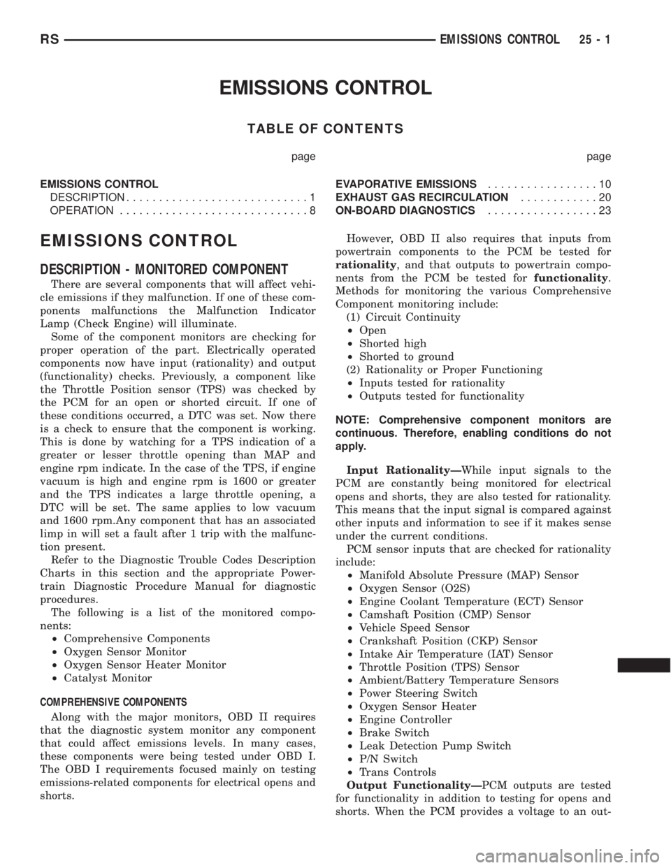
There are several components that will affect vehi-
cle emissions if they malfunction. If one of these com-
ponents malfunctions the Malfunction Indicator
Lamp (Check Engine) will illuminate.
Some of the component monitors are checking for
proper operation of the part. Electrically operated
components now have input (rationality) and output
(functionality) checks. Previously, a component like
the Throttle Position sensor (TPS) was checked by
the PCM for an open or shorted circuit. If one of
these conditions occurred, a DTC was set. Now there
is a check to ensure that the component is working.
This is done by watching for a TPS indication of a
greater or lesser throttle opening than MAP and
engine rpm indicate. In the case of the TPS, if engine
vacuum is high and engine rpm is 1600 or greater
and the TPS indicates a large throttle opening, a
DTC will be set. The same applies to low vacuum
and 1600 rpm.Any component that has an associated
limp in will set a fault after 1 trip with the malfunc-
tion present.
Refer to the Diagnostic Trouble Codes Description
Charts in this section and the appropriate Power-
train Diagnostic Procedure Manual for diagnostic
procedures.
The following is a list of the monitored compo-
nents:
²Comprehensive Components
²Oxygen Sensor Monitor
²Oxygen Sensor Heater Monitor
²Catalyst Monitor
COMPREHENSIVE COMPONENTS
Along with the major monitors, OBD II requires
that the diagnostic system monitor any component
that could affect emissions levels. In many cases,
these components were being tested under OBD I.
The OBD I requirements focused mainly on testing
emissions-related components for electrical opens and
shorts.However, OBD II also requires that inputs from
powertrain components to the PCM be tested for
rationality, and that outputs to powertrain compo-
nents from the PCM be tested forfunctionality.
Methods for monitoring the various Comprehensive
Component monitoring include:
(1) Circuit Continuity
²Open
²Shorted high
²Shorted to ground
(2) Rationality or Proper Functioning
²Inputs tested for rationality
²Outputs tested for functionality
NOTE: Comprehensive component monitors are
continuous. Therefore, enabling conditions do not
apply.
Input RationalityÐWhile input signals to the
PCM are constantly being monitored for electrical
opens and shorts, they are also tested for rationality.
This means that the input signal is compared against
other inputs and information to see if it makes sense
under the current conditions.
PCM sensor inputs that are checked for rationality
include:
²Manifold Absolute Pressure (MAP) Sensor
²Oxygen Sensor (O2S)
²Engine Coolant Temperature (ECT) Sensor
²Camshaft Position (CMP) Sensor
²Vehicle Speed Sensor
²Crankshaft Position (CKP) Sensor
²Intake Air Temperature (IAT) Sensor
²Throttle Position (TPS) Sensor
²Ambient/Battery Temperature Sensors
²Power Steering Switch
²Oxygen Sensor Heater
²Engine Controller
²Brake Switch
²Leak Detection Pump Switch
²P/N Switch
²Trans Controls
Output FunctionalityÐPCM outputs are tested
for functionality in addition to testing for opens and
shorts. When the PCM provides a voltage to an out-
RSEMISSIONS CONTROL25-1
Page 3754 of 4284
PCM calculates the A/F mixture from the output of
the O2S. A low voltage indicates high oxygen content
(lean mixture). A high voltage indicates a low content
of oxygen (rich mixture).
When the upstream O2S detects a lean condition,
there is an abundance of oxygen in the exhaust gas.
A functioning converter would store this oxygen so it
can use it for the oxidation of HC and CO. As the
converter absorbs the oxygen, there will be a lack of
oxygen downstream of the converter. The output of
the downstream O2S will indicate limited activity in
this condition.
As the converter loses the ability to store oxygen,
the condition can be detected from the behavior of
the downstream O2S. When the efficiency drops, no
chemical reaction takes place. This means the con-
centration of oxygen will be the same downstream as
upstream. The output voltage of the downstream
O2S copies the voltage of the upstream sensor. The
only difference is a time lag (seen by the PCM)
between the switching of the O2S's.
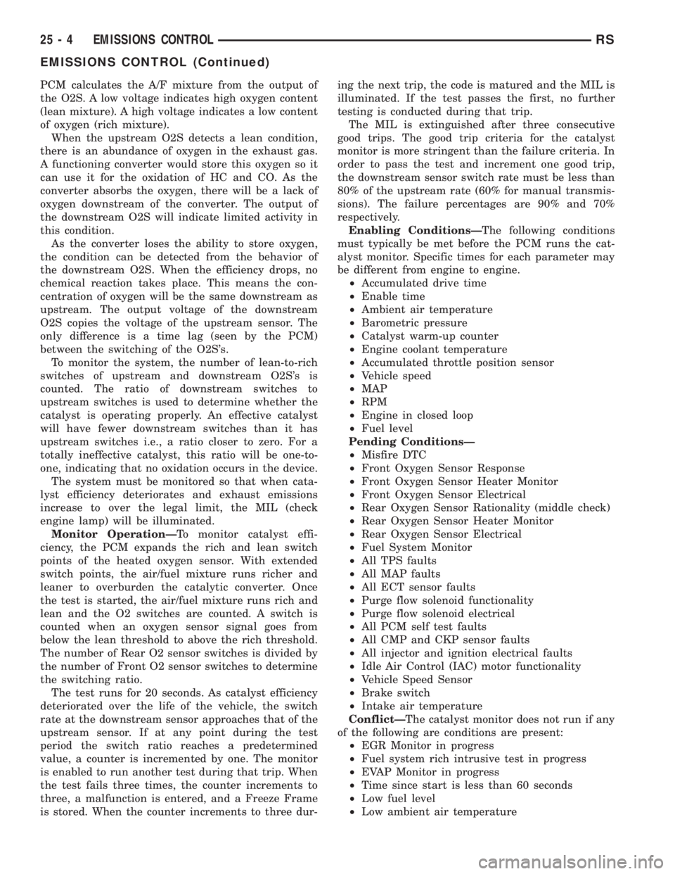
To monitor the system, the number of lean-to-rich
switches of upstream and downstream O2S's is
counted. The ratio of downstream switches to
upstream switches is used to determine whether the
catalyst is operating properly. An effective catalyst
will have fewer downstream switches than it has
upstream switches i.e., a ratio closer to zero. For a
totally ineffective catalyst, this ratio will be one-to-
one, indicating that no oxidation occurs in the device.
The system must be monitored so that when cata-
lyst efficiency deteriorates and exhaust emissions
increase to over the legal limit, the MIL (check
engine lamp) will be illuminated.
Monitor OperationÐTo monitor catalyst effi-
ciency, the PCM expands the rich and lean switch
points of the heated oxygen sensor. With extended
switch points, the air/fuel mixture runs richer and
leaner to overburden the catalytic converter. Once
the test is started, the air/fuel mixture runs rich and
lean and the O2 switches are counted. A switch is
counted when an oxygen sensor signal goes from
below the lean threshold to above the rich threshold.
The number of Rear O2 sensor switches is divided by
the number of Front O2 sensor switches to determine
the switching ratio.
The test runs for 20 seconds. As catalyst efficiency
deteriorated over the life of the vehicle, the switch
rate at the downstream sensor approaches that of the
upstream sensor. If at any point during the test
period the switch ratio reaches a predetermined
value, a counter is incremented by one. The monitor
is enabled to run another test during that trip. When
the test fails three times, the counter increments to
three, a malfunction is entered, and a Freeze Frame
is stored. When the counter increments to three dur-ing the next trip, the code is matured and the MIL is
illuminated. If the test passes the first, no further
testing is conducted during that trip.
The MIL is extinguished after three consecutive
good trips. The good trip criteria for the catalyst
monitor is more stringent than the failure criteria. In
order to pass the test and increment one good trip,
the downstream sensor switch rate must be less than
80% of the upstream rate (60% for manual transmis-
sions). The failure percentages are 90% and 70%
respectively.
Enabling ConditionsÐThe following conditions
must typically be met before the PCM runs the cat-
alyst monitor. Specific times for each parameter may
be different from engine to engine.
²Accumulated drive time
²Enable time
²Ambient air temperature
²Barometric pressure
²Catalyst warm-up counter
²Engine coolant temperature
²Accumulated throttle position sensor
²Vehicle speed
²MAP
²RPM
²Engine in closed loop
²Fuel level
Pending ConditionsÐ
²Misfire DTC
²Front Oxygen Sensor Response
²Front Oxygen Sensor Heater Monitor
²Front Oxygen Sensor Electrical
²Rear Oxygen Sensor Rationality (middle check)
²Rear Oxygen Sensor Heater Monitor
²Rear Oxygen Sensor Electrical
²Fuel System Monitor
²All TPS faults
²All MAP faults
²All ECT sensor faults
²Purge flow solenoid functionality
²Purge flow solenoid electrical
²All PCM self test faults
²All CMP and CKP sensor faults
²All injector and ignition electrical faults
²Idle Air Control (IAC) motor functionality
²Vehicle Speed Sensor
²Brake switch
²Intake air temperature
ConflictÐThe catalyst monitor does not run if any
of the following are conditions are present:
²EGR Monitor in progress
²Fuel system rich intrusive test in progress
²EVAP Monitor in progress
²Time since start is less than 60 seconds
²Low fuel level
²Low ambient air temperature
25 - 4 EMISSIONS CONTROLRS
EMISSIONS CONTROL (Continued)
Page 3779 of 4284
EXHAUST GAS RECIRCULATION
TABLE OF CONTENTS
page page
EXHAUST GAS RECIRCULATION
DESCRIPTION............................3
OPERATION.............................3
VA LV E
DESCRIPTION............................3
OPERATION.............................4REMOVAL...............................4
INSTALLATION............................4
VALVE COOLER
DESCRIPTION............................4
REMOVAL...............................4
INSTALLATION............................5
EXHAUST GAS
RECIRCULATION
DESCRIPTION
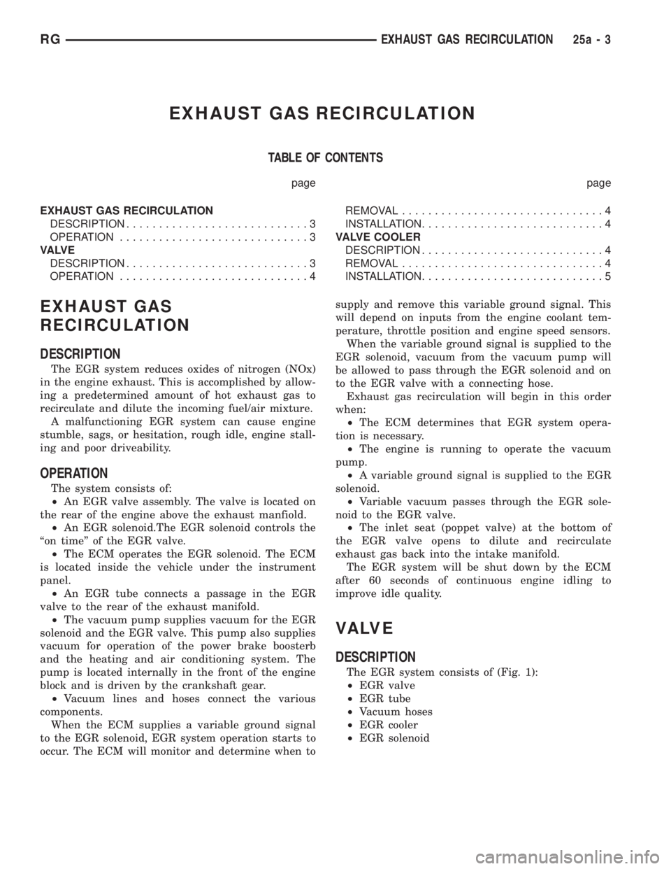
The EGR system reduces oxides of nitrogen (NOx)
in the engine exhaust. This is accomplished by allow-
ing a predetermined amount of hot exhaust gas to
recirculate and dilute the incoming fuel/air mixture.
A malfunctioning EGR system can cause engine
stumble, sags, or hesitation, rough idle, engine stall-
ing and poor driveability.
OPERATION
The system consists of:
²An EGR valve assembly. The valve is located on
the rear of the engine above the exhaust manfiold.
²An EGR solenoid.The EGR solenoid controls the
ªon timeº of the EGR valve.
²The ECM operates the EGR solenoid. The ECM
is located inside the vehicle under the instrument
panel.
²An EGR tube connects a passage in the EGR
valve to the rear of the exhaust manifold.
²The vacuum pump supplies vacuum for the EGR
solenoid and the EGR valve. This pump also supplies
vacuum for operation of the power brake boosterb
and the heating and air conditioning system. The
pump is located internally in the front of the engine
block and is driven by the crankshaft gear.
²Vacuum lines and hoses connect the various
components.
When the ECM supplies a variable ground signal
to the EGR solenoid, EGR system operation starts to
occur. The ECM will monitor and determine when tosupply and remove this variable ground signal. This
will depend on inputs from the engine coolant tem-
perature, throttle position and engine speed sensors.
When the variable ground signal is supplied to the
EGR solenoid, vacuum from the vacuum pump will
be allowed to pass through the EGR solenoid and on
to the EGR valve with a connecting hose.
Exhaust gas recirculation will begin in this order
when:
²The ECM determines that EGR system opera-
tion is necessary.
²The engine is running to operate the vacuum
pump.
²A variable ground signal is supplied to the EGR
solenoid.
²Variable vacuum passes through the EGR sole-
noid to the EGR valve.
²The inlet seat (poppet valve) at the bottom of
the EGR valve opens to dilute and recirculate
exhaust gas back into the intake manifold.
The EGR system will be shut down by the ECM
after 60 seconds of continuous engine idling to
improve idle quality.
VA LV E
DESCRIPTION
The EGR system consists of (Fig. 1):
²EGR valve
²EGR tube
²Vacuum hoses
²EGR cooler
²EGR solenoid
RGEXHAUST GAS RECIRCULATION25a-3
Page 3786 of 4284
Generic Scan Tool Code DRB IIITScan Tool Display
P1703 Brake Switch Signal CKTS Plaus. With Redundant Contact After
Initialization
P2120 Acc. Pedal Position Sensor 1 CKT Plausibility
Acc. Pedal Position Sensor 1 CKT Plausibility With Brake Switch
Acc. Pedal Position Sensor 1 CKT Plausibility With Potentiometer
Acc. Pedal Position Sensor 1 CKT Signal Voltage Too High
Acc. Pedal Position Sensor 1 CKT Signal Voltage Too Low
Acc. Pedal Position Sensor 1 CKT Signal Voltage Too High or Low
25a - 10 ON-BOARD DIAGNOSTICSRG
ON-BOARD DIAGNOSTICS (Continued)
Page 3791 of 4284
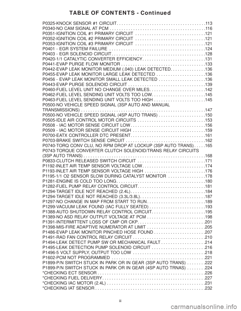
TABLE OF CONTENTS - Continued
P0325-KNOCK SENSOR #1 CIRCUIT......................................113
P0340-NO CAM SIGNAL AT PCM.........................................116
P0351-IGNITION COIL #1 PRIMARY CIRCUIT..............................121
P0352-IGNITION COIL #2 PRIMARY CIRCUIT..............................121
P0353-IGNITION COIL #3 PRIMARY CIRCUIT..............................121
P0401 - EGR SYSTEM FAILURE.........................................124
P0403 - EGR SOLENOID CIRCUIT........................................128
P0420-1/1 CATALYTIC CONVERTER EFFICIENCY...........................131
P0441-EVAP PURGE FLOW MONITOR....................................133
P0442-EVAP LEAK MONITOR MEDIUM (.040) LEAK DETECTED...............136
P0455-EVAP LEAK MONITOR LARGE LEAK DETECTED.....................136
P0456 - EVAP LEAK MONITOR SMALL LEAK DETECTED....................136
P0443-EVAP PURGE SOLENOID CIRCUIT.................................139
P0460-FUEL LEVEL UNIT NO CHANGE OVER MILES........................142
P0462-FUEL LEVEL SENDING UNIT VOLTS TOO LOW.......................145
P0463-FUEL LEVEL SENDING UNIT VOLTS TOO HIGH......................145
P0500-NO VEHICLE SPEED SIGNAL (3SP AUTO AND MANUAL
TRANSMISSIONS).....................................................147
P0500-NO VEHICLE SPEED SIGNAL (4SP AUTO TRANS)....................150
P0505-IDLE AIR CONTROL MOTOR CIRCUITS.............................153
P0508 - IAC MOTOR SENSE CIRCUIT LOW................................156
P0509 - IAC MOTOR SENSE CIRCUIT HIGH...............................159
P0700-EATX CONTROLLER DTC PRESENT................................161
P0703-BRAKE SWITCH SENSE CIRCUIT..................................162
P0740-TORQ CONV CLU, NO RPM DROP AT LOCKUP (3SP AUTO TRANS).....165
P0743-TORQUE CONVERTER CLUTCH SOLENOID/TRANS RELAY CIRCUITS
(3SP AUTO TRANS)....................................................168
P0833-CLUTCH RELEASED SWITCH CIRCUIT.............................171
P1192-INLET AIR TEMP SENSOR VOLTAGE LOW...........................174
P1193-INLET AIR TEMP SENSOR VOLTAGE HIGH..........................176
P1195-1/1 O2 SENSOR SLOW DURING CATALYST MONITOR................178
P1281-ENGINE IS COLD TOO LONG......................................180
P1282-FUEL PUMP RELAY CONTROL CIRCUIT.............................181
P1294-TARGET IDLE NOT REACHED (2.4L)................................184
P1294-TARGET IDLE NOT REACHED (3.3L/3.8L)............................187
P1297-NO CHANGE IN MAP FROM START TO RUN.........................189
P1299-VACUUM LEAK FOUND (IAC FULLY SEATED)........................193
P1388-AUTO SHUTDOWN RELAY CONTROL CIRCUIT.......................195
P1389-NO ASD RELAY OUTPUT VOLTAGE AT PCM.........................198
P1391-INTERMITTENT LOSS OF CMP OR CKP.............................201
P1398-MIS-FIRE ADAPTIVE NUMERATOR AT LIMIT.........................205
P1486-EVAP LEAK MONITOR PINCHED HOSE FOUND......................207
P1491-RAD FAN CONTROL RELAY CIRCUIT...............................210
P1494-LEAK DETECT PUMP SW OR MECHANICAL FAULT...................214
P1495-LEAK DETECTION PUMP SOLENOID CIRCUIT.......................216
P1496-5 VOLT SUPPLY, OUTPUT TOO LOW...............................218
P1602-PCM NOT PROGRAMMED........................................221
P1899-P/N SWITCH STUCK IN PARK OR IN GEAR (3SP AUTO TRANS)........222
P1899-P/N SWITCH STUCK IN PARK OR IN GEAR (4SP AUTO TRNAS)........224
*CHECKING ECT SENSOR..............................................226
*CHECKING FUEL DELIVERY............................................227
*CHECKING IAC MOTOR (2.4L)..........................................231
*CHECKING IAT SENSOR...............................................232
iii
Page 3793 of 4284
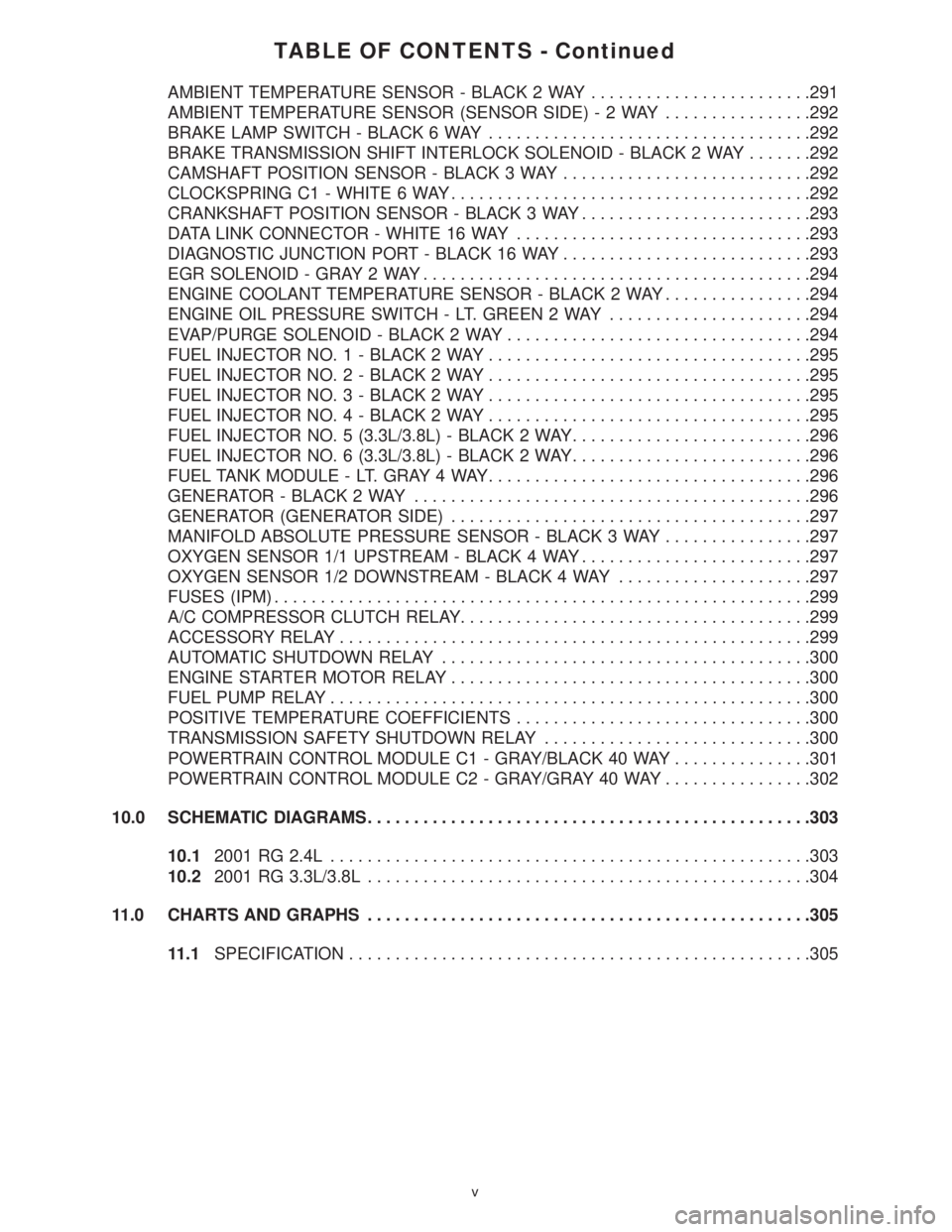
TABLE OF CONTENTS - Continued
AMBIENT TEMPERATURE SENSOR - BLACK 2 WAY........................291
AMBIENT TEMPERATURE SENSOR (SENSOR SIDE)-2WAY................292
BRAKE LAMP SWITCH - BLACK 6 WAY...................................292
BRAKE TRANSMISSION SHIFT INTERLOCK SOLENOID - BLACK 2 WAY.......292
CAMSHAFT POSITION SENSOR - BLACK 3 WAY...........................292
CLOCKSPRING C1 - WHITE 6 WAY.......................................292
CRANKSHAFT POSITION SENSOR - BLACK 3 WAY.........................293
DATA LINK CONNECTOR - WHITE 16 WAY................................293
DIAGNOSTIC JUNCTION PORT - BLACK 16 WAY...........................293
EGR SOLENOID - GRAY 2 WAY..........................................294
ENGINE COOLANT TEMPERATURE SENSOR - BLACK 2 WAY................294
ENGINE OIL PRESSURE SWITCH - LT. GREEN 2 WAY......................294
EVAP/PURGE SOLENOID - BLACK 2 WAY.................................294
FUEL INJECTOR NO. 1 - BLACK 2 WAY...................................295
FUEL INJECTOR NO. 2 - BLACK 2 WAY...................................295
FUEL INJECTOR NO. 3 - BLACK 2 WAY...................................295
FUEL INJECTOR NO. 4 - BLACK 2 WAY...................................295
FUEL INJECTOR NO. 5 (3.3L/3.8L) - BLACK 2 WAY..........................296
FUEL INJECTOR NO. 6 (3.3L/3.8L) - BLACK 2 WAY..........................296
FUEL TANK MODULE - LT. GRAY 4 WAY...................................296
GENERATOR - BLACK 2 WAY...........................................296
GENERATOR (GENERATOR SIDE).......................................297
MANIFOLD ABSOLUTE PRESSURE SENSOR - BLACK 3 WAY................297
OXYGEN SENSOR 1/1 UPSTREAM - BLACK 4 WAY.........................297
OXYGEN SENSOR 1/2 DOWNSTREAM - BLACK 4 WAY.....................297
FUSES (IPM)..........................................................299
A/C COMPRESSOR CLUTCH RELAY......................................299
ACCESSORY RELAY...................................................299
AUTOMATIC SHUTDOWN RELAY........................................300
ENGINE STARTER MOTOR RELAY.......................................300
FUEL PUMP RELAY....................................................300
POSITIVE TEMPERATURE COEFFICIENTS................................300
TRANSMISSION SAFETY SHUTDOWN RELAY.............................300
POWERTRAIN CONTROL MODULE C1 - GRAY/BLACK 40 WAY...............301
POWERTRAIN CONTROL MODULE C2 - GRAY/GRAY 40 WAY................302
10.0 SCHEMATIC DIAGRAMS................................................303
10.12001 RG 2.4L....................................................303
10.22001 RG 3.3L/3.8L................................................304
11.0 CHARTS AND GRAPHS................................................305
11.1SPECIFICATION..................................................305
v
Page 3804 of 4284
SYMPTOM DIAGNOSTIC TEST
POOR FUEL ECONOMY CHECKING PCM POWER AND GND CKT
CHECKING THE FUEL PRESSURE
CHECKING ECT SENSOR
CHECKING THROTTLE POSITION SENSOR
CHECKING MAP SENSOR
CHECKING IDLE AIR CONTROL MOTOR OPERATION
CHECKING IAT SENSOR
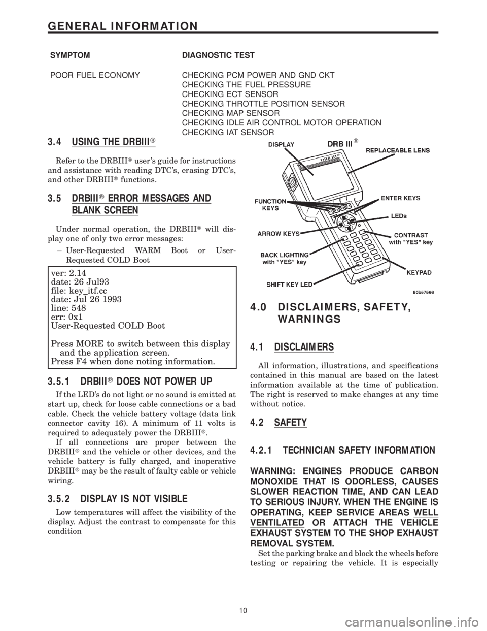
3.4 USING THE DRBIIIT
Refer to the DRBIIItuser 's guide for instructions
and assistance with reading DTC's, erasing DTC's,
and other DRBIIItfunctions.
3.5 DRBIIITERROR MESSAGES AND
BLANK SCREEN
Under normal operation, the DRBIIItwill dis-
play one of only two error messages:
± User-Requested WARM Boot or User-
Requested COLD Boot
ver: 2.14
date: 26 Jul93
file: key_itf.cc
date: Jul 26 1993
line: 548
err: 0x1
User-Requested COLD Boot
Press MORE to switch between this display
and the application screen.
Press F4 when done noting information.
3.5.1 DRBIIITDOES NOT POWER UP
If the LED's do not light or no sound is emitted at
start up, check for loose cable connections or a bad
cable. Check the vehicle battery voltage (data link
connector cavity 16). A minimum of 11 volts is
required to adequately power the DRBIIIt.
If all connections are proper between the
DRBIIItand the vehicle or other devices, and the
vehicle battery is fully charged, and inoperative
DRBIIItmay be the result of faulty cable or vehicle
wiring.
3.5.2 DISPLAY IS NOT VISIBLE
Low temperatures will affect the visibility of the
display. Adjust the contrast to compensate for this
condition
4.0 DISCLAIMERS, SAFETY,
WARNINGS
4.1 DISCLAIMERS
All information, illustrations, and specifications
contained in this manual are based on the latest
information available at the time of publication.
The right is reserved to make changes at any time
without notice.
4.2 SAFETY
4.2.1 TECHNICIAN SAFETY INFORMATION
WARNING: ENGINES PRODUCE CARBON
MONOXIDE THAT IS ODORLESS, CAUSES
SLOWER REACTION TIME, AND CAN LEAD
TO SERIOUS INJURY. WHEN THE ENGINE IS
OPERATING, KEEP SERVICE AREAS WELL
VENTILATED OR ATTACH THE VEHICLE
EXHAUST SYSTEM TO THE SHOP EXHAUST
REMOVAL SYSTEM.
Set the parking brake and block the wheels before
testing or repairing the vehicle. It is especially
10
GENERAL INFORMATION
Page 3806 of 4284
When testing voltage or continuity at any control
module, use the terminal side (not the wire end) of
the connector. Do not probe a wire through the
insulation; this will damage it and eventually cause
it to fail because of corrosion.
Be careful when performing electrical tests so as
to prevent accidental shorting of terminals. Such
mistakes can damage fuses or components. Also, a
second DTC could be set, making diagnosis of the
original problem more difficult.
5.0 REQUIRED TOOLS AND
EQUIPMENT
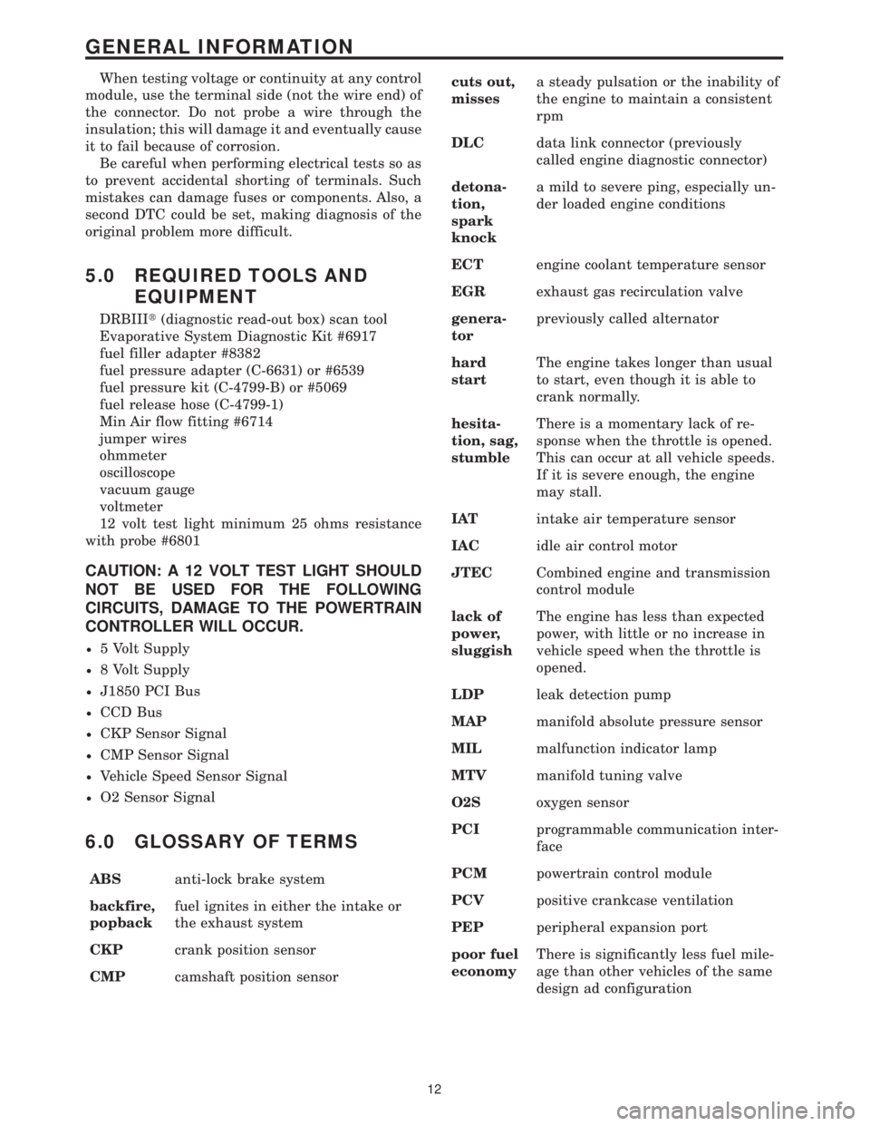
DRBIIIt(diagnostic read-out box) scan tool
Evaporative System Diagnostic Kit #6917
fuel filler adapter #8382
fuel pressure adapter (C-6631) or #6539
fuel pressure kit (C-4799-B) or #5069
fuel release hose (C-4799-1)
Min Air flow fitting #6714
jumper wires
ohmmeter
oscilloscope
vacuum gauge
voltmeter
12 volt test light minimum 25 ohms resistance
with probe #6801
CAUTION: A 12 VOLT TEST LIGHT SHOULD
NOT BE USED FOR THE FOLLOWING
CIRCUITS, DAMAGE TO THE POWERTRAIN
CONTROLLER WILL OCCUR.
²5 Volt Supply
²8 Volt Supply
²J1850 PCI Bus
²CCD Bus
²CKP Sensor Signal
²CMP Sensor Signal
²Vehicle Speed Sensor Signal
²O2 Sensor Signal
6.0 GLOSSARY OF TERMS
ABSanti-lock brake system
backfire,
popbackfuel ignites in either the intake or
the exhaust system
CKPcrank position sensor
CMPcamshaft position sensorcuts out,
missesa steady pulsation or the inability of
the engine to maintain a consistent
rpm
DLCdata link connector (previously
called engine diagnostic connector)
detona-
tion,
spark
knocka mild to severe ping, especially un-
der loaded engine conditions
ECTengine coolant temperature sensor
EGRexhaust gas recirculation valve
genera-
torpreviously called alternator
hard
startThe engine takes longer than usual
to start, even though it is able to
crank normally.
hesita-
tion, sag,
stumbleThere is a momentary lack of re-
sponse when the throttle is opened.
This can occur at all vehicle speeds.
If it is severe enough, the engine
may stall.
IATintake air temperature sensor
IACidle air control motor
JTECCombined engine and transmission
control module
lack of
power,
sluggishThe engine has less than expected
power, with little or no increase in
vehicle speed when the throttle is
opened.
LDPleak detection pump
MAPmanifold absolute pressure sensor
MILmalfunction indicator lamp
MTVmanifold tuning valve
O2Soxygen sensor
PCIprogrammable communication inter-
face
PCMpowertrain control module
PCVpositive crankcase ventilation
PEPperipheral expansion port
poor fuel
economyThere is significantly less fuel mile-
age than other vehicles of the same
design ad configuration
12
GENERAL INFORMATION
Page 3886 of 4284
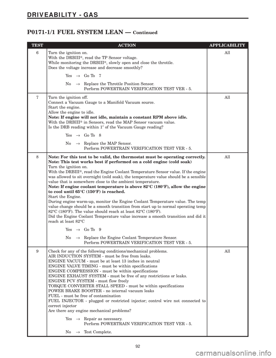
TEST ACTION APPLICABILITY
6 Turn the ignition on.
With the DRBIIIt, read the TP Sensor voltage.
While monitoring the DRBIIIt, slowly open and close the throttle.
Does the voltage increase and decrease smoothly?All
Ye s®Go To 7
No®Replace the Throttle Position Sensor.
Perform POWERTRAIN VERIFICATION TEST VER - 5.
7 Turn the ignition off.
Connect a Vacuum Gauge to a Manifold Vacuum source.
Start the engine.
Allow the engine to idle.
Note: If engine will not idle, maintain a constant RPM above idle.
With the DRBIIItin Sensors, read the MAP Sensor vacuum value.
Is the DRB reading within 19of the Vacuum Gauge reading?All
Ye s®Go To 8
No®Replace the MAP Sensor.
Perform POWERTRAIN VERIFICATION TEST VER - 5.
8Note: For this test to be valid, the thermostat must be operating correctly.
Note: This test works best if performed on a cold engine (cold soak)
Turn the ignition on.
With the DRBIIIt, read the Engine Coolant Temperature Sensor value. If the engine
was allowed to sit overnight (cold soak), the temperature value should be a sensible
value that is somewhere close to the ambient temperature.
Note: If engine coolant temperature is above 82ÉC (180ÉF), allow the engine
to cool until 65ÉC (150ÉF) is reached.
Start the Engine.
During engine warm-up, monitor the Engine Coolant Temperature value. The temp
value change should be a smooth transition from start up to normal operating temp
82ÉC (180ÉF). The value should reach at least 82ÉC (180ÉF).
Did the Engine Coolant Temperature value increase a smooth transition and did it
reach at least 82ÉCAll
Ye s®Go To 9
No®Replace the Engine Coolant Temperature Sensor.
Perform POWERTRAIN VERIFICATION TEST VER - 5.
9 Check for any of the following conditions/mechanical problems.
AIR INDUCTION SYSTEM - must be free from leaks.
ENGINE VACUUM - must be at least 13 inches in neutral
ENGINE VALVE TIMING - must be within specifications
ENGINE COMPRESSION - must be within specifications
ENGINE EXHAUST SYSTEM - must be free of any restrictions or leaks.
ENGINE PCV SYSTEM - must flow freely
TORQUE CONVERTER STALL SPEED - must be within specifications
POWER BRAKE BOOSTER - no internal vacuum leaks
FUEL - must be free of contamination
FUEL INJECTOR - plugged or restricted injector; control wire not connected to
correct injector
Are there any engine mechanical problems?All
Ye s®Repair as necessary.
Perform POWERTRAIN VERIFICATION TEST VER - 5.
No®Test Complete.
92
DRIVEABILITY - GAS
P0171-1/1 FUEL SYSTEM LEAN ÐContinued
Page 3892 of 4284
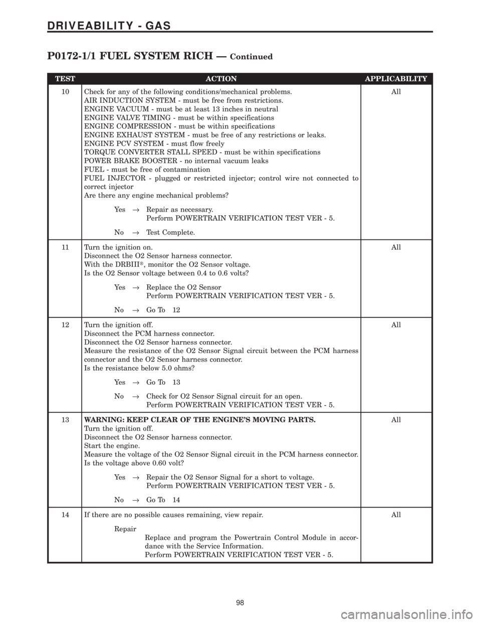
TEST ACTION APPLICABILITY
10 Check for any of the following conditions/mechanical problems.
AIR INDUCTION SYSTEM - must be free from restrictions.
ENGINE VACUUM - must be at least 13 inches in neutral
ENGINE VALVE TIMING - must be within specifications
ENGINE COMPRESSION - must be within specifications
ENGINE EXHAUST SYSTEM - must be free of any restrictions or leaks.
ENGINE PCV SYSTEM - must flow freely
TORQUE CONVERTER STALL SPEED - must be within specifications
POWER BRAKE BOOSTER - no internal vacuum leaks
FUEL - must be free of contamination
FUEL INJECTOR - plugged or restricted injector; control wire not connected to
correct injector
Are there any engine mechanical problems?All
Ye s®Repair as necessary.
Perform POWERTRAIN VERIFICATION TEST VER - 5.
No®Test Complete.
11 Turn the ignition on.
Disconnect the O2 Sensor harness connector.
With the DRBIIIt, monitor the O2 Sensor voltage.
Is the O2 Sensor voltage between 0.4 to 0.6 volts?All
Ye s®Replace the O2 Sensor
Perform POWERTRAIN VERIFICATION TEST VER - 5.
No®Go To 12
12 Turn the ignition off.
Disconnect the PCM harness connector.
Disconnect the O2 Sensor harness connector.
Measure the resistance of the O2 Sensor Signal circuit between the PCM harness
connector and the O2 Sensor harness connector.
Is the resistance below 5.0 ohms?All
Ye s®Go To 13
No®Check for O2 Sensor Signal circuit for an open.
Perform POWERTRAIN VERIFICATION TEST VER - 5.
13WARNING: KEEP CLEAR OF THE ENGINE'S MOVING PARTS.
Turn the ignition off.
Disconnect the O2 Sensor harness connector.
Start the engine.
Measure the voltage of the O2 Sensor Signal circuit in the PCM harness connector.
Is the voltage above 0.60 volt?All
Ye s®Repair the O2 Sensor Signal for a short to voltage.
Perform POWERTRAIN VERIFICATION TEST VER - 5.
No®Go To 14
14 If there are no possible causes remaining, view repair. All
Repair
Replace and program the Powertrain Control Module in accor-
dance with the Service Information.
Perform POWERTRAIN VERIFICATION TEST VER - 5.
98
DRIVEABILITY - GAS
P0172-1/1 FUEL SYSTEM RICH ÐContinued