ESP inoperative CHRYSLER VOYAGER 2001 User Guide
[x] Cancel search | Manufacturer: CHRYSLER, Model Year: 2001, Model line: VOYAGER, Model: CHRYSLER VOYAGER 2001Pages: 4284, PDF Size: 83.53 MB
Page 1181 of 4284

Symptom:
RIGHT FRONT WHEEL SPEED SIGNAL FAILURE
When Monitored and Set Condition:
RIGHT FRONT WHEEL SPEED SIGNAL FAILURE
When Monitored: Wheel speed comparison is checked at drive off or every 7 milliseconds
(ms). Wheel speed continuity is checked every 7 milliseconds. Wheel speed phase length
supervision is checked every 7 milliseconds.
Set Condition: If, during an ABS stop, the CAB commands any valve solenoid on for an
extended length of time, and does not see a corresponding wheel speed change, the
Diagnostic Trouble Code (DTC) is set. The DTC can also set if the signal is missing or
erratic.
POSSIBLE CAUSES
SENSOR OR TONE WHEEL CONCERN
DTC INTERMITTENT
RIGHT FRONT WHEEL SPEED SENSOR INOPERATIVE
CAB - WON'T RESPOND TO RIGHT FRONT WHEEL SPEED SENSOR SIGNAL
INTERMITTENT SIGNAL DTC
TEST ACTION APPLICABILITY
1 With the DRBIIIt, erase DTCs.
Turn the ignition off.
Start the engine.
Slowly accelerate as straight as possible from a stop to 24 km/h (15 mph).
Using the DRBIIIt, monitor the Right Front Wheel Speed Sensor while an assistant
drives the vehicle.
With the DRBIIIt, monitor all wheel speed sensors.
Is Right Front WSS Signal 0 km/h (0 mph) or differing from others by more than 5
km/h (3 mph)?All
Ye s®Go To 2
No®Go To 3
2 Inspect the Right Front Wheel Speed Sensor, Connector and Tone Wheel.
NOTE: Inspect components for damage and correct installation.
Are there any visible Sensor, Connector or Tone Wheel concerns?All
Ye s®Correct the sensor, connector or tone wheel concern as necessary.
The vehicle must be driven at 25 km/h (15 mph) to extinguish the
ABS indicator.
Perform ABS VERIFICATION TEST - VER 1.
No®Replace the Right Front Wheel Speed Sensor in accordance with
the Service Information. The vehicle must be driven at 25 km/h
(15 mph) to extinguish the ABS indicator.
Perform ABS VERIFICATION TEST - VER 1.
24
BRAKES (CAB)
Page 1183 of 4284

Symptom:
RIGHT REAR WHEEL SPEED SIGNAL FAILURE
When Monitored and Set Condition:
RIGHT REAR WHEEL SPEED SIGNAL FAILURE
When Monitored: Wheel speed comparison is checked at drive off or every 7 milliseconds
(ms). Wheel speed circuit continuity is checked every 7 milliseconds. Wheel speed phase
length supervision is checked every 7 milliseconds.
Set Condition: If, during an ABS stop, the CAB commands any valve solenoid on for an
extended length of time, and does not see a corresponding wheel speed change, the
Diagnostic Trouble Code (DTC) is set. The DTC can also set if the signal is missing or
erratic.
POSSIBLE CAUSES
SENSOR OR TONE WHEEL CONCERN
DTC INTERMITTENT
RIGHT REAR WHEEL SPEED SENSOR INOPERATIVE
INTERMITTENT SIGNAL DTC
TEST ACTION APPLICABILITY
1 With the DRBIIIt, erase DTCs.
Turn the ignition off.
Start the engine.
Slowly accelerate as straight as possible from a stop to 24 km/h (15 mph).
Using the DRBIIIt, monitor the Right Rear Wheel Speed Sensor while an assistant
drives the vehicle.
With the DRBIIIt, monitor all wheel speed sensors.
Is Right Rear WSS Signal 0 km/h (0 mph) or differing from others by more than 5
km/h (3 mph)?All
Ye s®Go To 2
No®Go To 3
2 Inspect the Right Rear Wheel Speed Sensor, Connector and Tone Wheel.
NOTE: Inspect components for damage and correct installation.
Are there any visible Sensor, Connector or Tone Wheel concerns?All
Ye s®Correct the sensor, connector or tone wheel concern as necessary.
The vehicle must be driven at 25 km/h (15 mph) to extinguish the
ABS indicator.
Perform ABS VERIFICATION TEST - VER 1.
No®Replace the Left Rear Wheel Speed Sensor in accordance with the
Service Information. The vehicle must be driven at 25 km/h (15
mph) to extinguish the ABS indicator.
Perform ABS VERIFICATION TEST - VER 1.
26
BRAKES (CAB)
Page 1225 of 4284
J1850 COMMUNICATION BUS SPI ERROR
J1850 COMMUNICATION BUS RECEIVE TIME-
OUT
J1850 COMMUNICATION BUS UNAUTHO-
RIZED RESET
EEPROM PLAUSIBILITY CHECKSUM ERROR
EEPROM PLAUSIBILITY VIN CHECKSUM
ERROR
EEPROM PLAUSIBILITY COMMUNICATION
ERROR
EEPROM PLAUSIBILITY WRITE ERROR
EEPROM PLAUSIBILITY VARIATION NUM-
BER ERROR
EEPROM PLAUSIBILITY CODE WORD IN-
CORRECT OR MISSING
SKIM SYSTEM SKIM ERROR
SKIM SYSTEM WRITE ACCESS TO EEPROM
FAILURE
SKIM SYSTEM INVALID SECRET KEY IN EE-
PROM
SKIM SYSTEM KEY COMMUNICATION
TIMED OUT
SKIM SYSTEM INVALID KEY CODE RE-
CEIVED
EEPROM RECOVERY OCCURRED
EEPROM REDUNDANT OVERRUN MONI-
TORING
EEPROM QUANTITY STOP
EEPROM COMMUNICATION ERROR
EEPROM COMMUNICATION NOT VERIFIED
ACC PEDAL POSITION SENSOR 1 CKT SIG-
NAL VOLTAGE TOO HIGH
ACC PEDAL POSITION SENSOR 1 CKT SIG-
NAL VOLTAGE TOO LOW
ACC PEDAL POSITION SENSOR 1 CKT SUP-
PLY VOLTAGE TOO HIGH OR LOW
ACC PEDAL POSITION SENSOR 1 CKT PLAU-
SIBILITY WITH POTENTIOMETER
ACC PEDAL POSITION SENSOR 1 CKT PLAU-
SIBILITY WITH BRAKE SWITCH
ACC PEDAL POSITION SENSOR 1 CKT PLAU-
SIBILITY
3.3.4 SKIM DIAGNOSTIC TROUBLE CODES
ANTENNA FAILURE
COP FAILURE
EEPROM FAILURE
PCM STATUS FAILURE
INTERNAL FAULT
RAM FAILURE
ROLLING CODE FAILURE
SERIAL LINK EXTERNAL FAULT
SERIAL LINK INTERNAL FAULT
STACK OVERFLOW FAILURE
TRANSPONDER COMMUNICATION FAILURE
TRANSPONDER CRC (CYCLIC REDUN-
DANCY CHECK) FAILURE
TRANSPONDER ID MISMATCHTRANSPONDER RESPONSE MISMATCH
VIN MISMATCH
3.3.5 HANDLING NO TROUBLE CODE
PROBLEMS
After reading Section 3.0 (System Description
and Functional Operation), you should have a bet-
ter understanding of the theory and operation of the
on-board diagnostics, and how this relates to the
diagnosis of a vehicle that may have a driveability-
related symptom or complaint.
3.4 USING THE DRBIIIT
Refer to the DRBIIItuser 's guide for instructions
and assistance with reading the DTCs, erasing the
DTCs, lab scope usage and other DRBIIItfunc-
tions.
3.4.1 DRBIIITDOES NOT POWER UP
If the LEDs do not light or no sound is emitted at
start up, check for loose cable connections or a bad
cable. Check the vehicle battery voltage at data link
connector cavity 16. A minimum of 11.0 volts is
required to adequately power the DRB. Check for
proper ground connection at data link connector
cavities 4 and 5.
If all connections are proper between the
DRBIIItand the vehicle or other devices, and the
vehicle battery is fully charged, an inoperative
DRBIIItmay be the result of a faulty cable or
vehicle wiring. For a blank screen, refer to the
appropriate diagnostic manual.
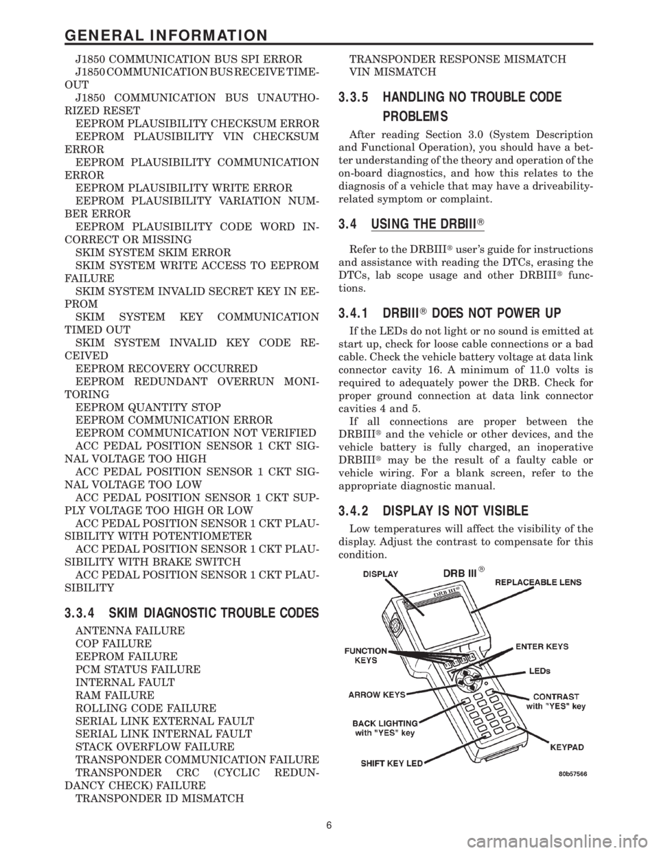
3.4.2 DISPLAY IS NOT VISIBLE
Low temperatures will affect the visibility of the
display. Adjust the contrast to compensate for this
condition.
6
GENERAL INFORMATION
Page 1847 of 4284
SKIM is properly installed on the steering column,
the antenna ring fits snugly around the circumfer-
ence of the ignition lock cylinder housing. If this ring
is not mounted properly, communication problems
may arise in the form of transponder-related faults.
For added system security, each SKIM is pro-
grammed with a unique9Secret Key9code. This code
is stored in memory and is sent over the PCI bus to
the PCM and to each key that is programmed to
work with the vehicle. The9Secret Key9code is there-
fore a common element found in all components of
the Sentry Key Immobilizer System (SKIS). In the
event that a SKIM replacement is required, the
9Secret Key9code can be restored from the PCM by
following the SKIM replacement procedure found in
the DRB IIItscan tool. Proper completion of this
task will allow the existing ignition keys to be repro-
grammed. Therefore, new keys will NOT be needed.
In the event that the original9Secret Key9code can
not be recovered, new ignition keys will be required.
The DRB IIItscan tool will alert the technician if
key replacement is necessary. Another security code,
called a PIN, is used to gain secured access to the
SKIM for service. The SKIM also stores in its mem-
ory the Vehicle Identification Number (VIN), which it
learns through a bus message from the assembly
plant tester. The SKIS scrambles the information
that is communicated between its components in
order to reduce the possibility of unauthorized SKIM
access and/or disabling.
OPERATION
When the ignition switch is moved to the RUN
position, the SKIM transmits an RF signal to the
transponder in the ignition key. The SKIM then
waits for a response RF signal from the transponder
in the key. If the response received identifies the key
as valid, the SKIM sends a9valid key9message to
the PCM over the PCI bus. If the response received
identifies the key as invalid or no response is
received from the transponder in the ignition key, the
SKIM sends an9invalid key9message to the PCM.
The PCM will enable or disable engine operation
based upon the status of the SKIM messages. It is
important to note that the default condition in the
PCM is9invalid key.9Therefore, if no response is
received by the PCM, the engine will be immobilized
after two (2) seconds of running.
The SKIM also sends indicator light status mes-
sages to the BCM to operate the light. This is the
method used to turn the light ON solid or to flash it
after the indicator light test is complete to signify a
fault in the SKIS. If the light comes ON and stays
ON solid after the indicator light test, this signifies
that the SKIM has detected a system malfunction
and/or that the SKIS has become inoperative. If theSKIM detects an invalid keyORa key-related fault
exists, the indicator light will flash following the
indicator light test. The SKIM may also request an
audible chime if the customer key programming fea-
ture is available and the procedure is being utilized.
Refer to Electrical, Vehicle Theft Security, Transpon-
der Key, Standard Procedure - Transponder Program-
ming.
REMOVAL
(1) Disconnect and isolate the battery negative
cable.
(2) Remove Lower Instrument Panel Cover. Refer
to Body, Instrument Panel, Lower Instrument Panel
Cover, Removal.
(3) Remove the steering column upper and lower
shrouds. Refer to Steering, Column, Column Shroud,
Removal.
(4) Disengage the steering column wire harness
from the Sentry Key Immobilizer Module (SKIM).
(5) Remove the one screws securing the SKIM to
the steering column.
(6) Rotate the SKIM upwards and then to the side
away from the steering column to slide the SKIM
antenna ring from around the ignition switch lock
cylinder housing.
(7) Remove the SKIM from the vehicle.
INSTALLATION
(1) Slip the SKIM antenna ring around the igni-
tion switch lock cylinder housing. Rotate the SKIM
downwards and then towards the steering column.
(2) Install the one screws securing the SKIM to
the steering column.
(3) Engage the steering column wire harness from
the Sentry Key Immobilizer Module (SKIM).
(4) Install the steering column upper and lower
shrouds. Refer to Steering, Column, Column Shroud,
Installation.
(5) Install the Lower Instrument Panel Cover.
Refer to Body, Instrument Panel, Lower Instrument
Panel Cover, Installation.
(6) Connect the battery negative cable.
SLIDING DOOR CONTROL
MODULE
DESCRIPTION
Vehicles equipped with a power sliding door utilize
a sliding door control module. The sliding door con-
trol module is located behind the sliding door trim
panel in the center of the door, just above the sliding
door motor. This module controls the operation of the
door through the Programmable Communication
Interface (PCI) J1850 data bus circuit and the Body
RSELECTRONIC CONTROL MODULES8E-23
SENTRY KEY IMMOBILIZER MODULE (Continued)
Page 1905 of 4284
OPERATION
There are three positions that can be selected with
each of the heated seat switches: Off, Low, or High.
When the left side of the switch rocker is fully
depressed, the Low position is selected and the high
position LED indicator illuminates. When the right
side of the switch rocker is fully depressed, the High
position is selected and the low position LED indica-
tor illuminates. When the switch rocker is moved to
its neutral position (middle), Off is selected and both
LED indicators are extinguished.
Both switches provide separate resistor multi-
plexed hard wire inputs to the BCM to indicate the
selected switch position. The BCM monitors the
switch inputs and sends heated seat switch status
messages to the Heated Seat Module (HSM) or the
Memory Heated Seat Module (MHSM) over the Pro-
grammable Communications Interface (PCI) data
bus. The HSM or MHSM responds to the heated seat
switch status messages by controlling the output to
the seat heater elements of the selected seat. The
Low heat position set point is about 36É C (97É F),
and the High heat position set point is about 41É C
(105É F).
DIAGNOSIS & TESTING - HEATED SEAT
SWITCH
For complete circuit diagrams, refer toWiring
Diagrams.
WARNING: ON VEHICLES EQUIPPED WITH AIR-
BAGS, REFER TO THE RESTRAINTS SECTION OF
THIS MANUAL BEFORE ATTEMPTING ANY STEER-
ING WHEEL, STEERING COLUMN, SEAT OR
INSTRUMENT PANEL COMPONENT DIAGNOSIS OR
SERVICE. FAILURE TO TAKE THE PROPER PRE-
CAUTIONS COULD RESULT IN ACCIDENTAL AIR-
BAG DEPLOYMENT AND POSSIBLE PERSONAL
INJURY.
(1) Check the fused ignition switch output (run)
fuse in the intelligent power module. If OK, go to
Step 2. If not OK, repair the shorted circuit or com-
ponent as required and replace the faulty fuse.
(2) Turn the ignition switch to the On position.
Check for battery voltage at the fused ignition switch
output (run) fuse in the intelligent power module. If
OK, go to Step 3. If not OK, repair the open fused
ignition switch output (run) circuit to the ignition
switch as required.
(3) Disconnect and isolate the battery negative
cable. Remove the center bezel from the instrument
panel and disconnect the instrument panel wire har-
ness connectors from the heated seat switch connec-
tor receptacle. Check for continuity between the
ground circuit cavity of the instrument panel wireharness connector for the inoperative heated seat
switch(es) and a good ground. There should be conti-
nuity. If OK, go to Step 4. If not OK, repair the open
ground circuit to ground as required.
(4) Reconnect the battery negative cable. Turn the
ignition switch to the On position. Check for battery
voltage at the fused ignition switch output (run) cir-
cuit cavity of the instrument panel wire harness con-
nector for the inoperative heated seat switch(es). If
OK, turn the ignition switch to the Off position, dis-
connect and isolate the battery negative cable, and go
to Step 5. If not OK, repair the open fused ignition
switch output (run) circuit to the intelligent power
module fuse as required.
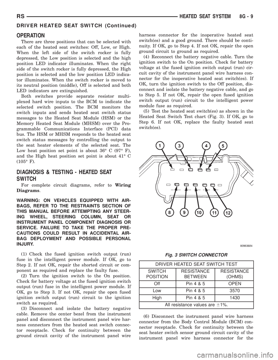
(5) Test the heated seat switch(es) as shown in the
Heated Seat Switch Test chart (Fig. 3). If OK, go to
Step 6. If not OK, replace the faulty heated seat
switch(es).
DRIVER HEATED SEAT SWITCH TEST
SWITCH
POSITIONRESISTANCE
BETWEENRESISTANCE
(OHMS)
Off Pin4&5OPEN
Low Pin4&53570
High Pin4&51430
All resistance values are61%.
(6) Disconnect the instrument panel wire harness
connector from the Body Control Module (BCM) con-
nector receptacle. Check for continuity between the
seat heater switch sensor ground circuit cavity of the
instrument panel wire harness connector for the
Fig. 3 SWITCH CONNECTOR
RSHEATED SEAT SYSTEM8G-9
DRIVER HEATED SEAT SWITCH (Continued)
Page 1908 of 4284
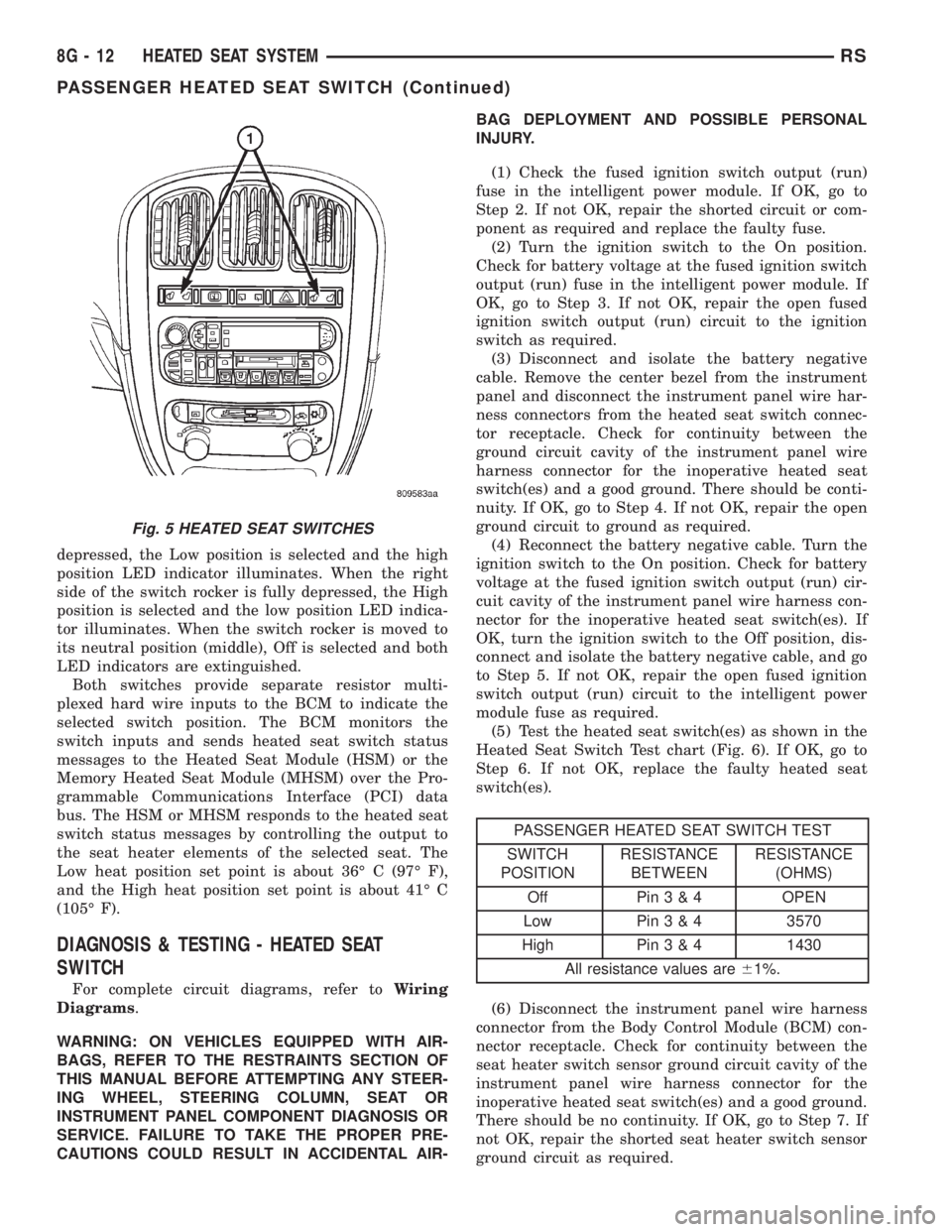
depressed, the Low position is selected and the high
position LED indicator illuminates. When the right
side of the switch rocker is fully depressed, the High
position is selected and the low position LED indica-
tor illuminates. When the switch rocker is moved to
its neutral position (middle), Off is selected and both
LED indicators are extinguished.
Both switches provide separate resistor multi-
plexed hard wire inputs to the BCM to indicate the
selected switch position. The BCM monitors the
switch inputs and sends heated seat switch status
messages to the Heated Seat Module (HSM) or the
Memory Heated Seat Module (MHSM) over the Pro-
grammable Communications Interface (PCI) data
bus. The HSM or MHSM responds to the heated seat
switch status messages by controlling the output to
the seat heater elements of the selected seat. The
Low heat position set point is about 36É C (97É F),
and the High heat position set point is about 41É C
(105É F).
DIAGNOSIS & TESTING - HEATED SEAT
SWITCH
For complete circuit diagrams, refer toWiring
Diagrams.
WARNING: ON VEHICLES EQUIPPED WITH AIR-
BAGS, REFER TO THE RESTRAINTS SECTION OF
THIS MANUAL BEFORE ATTEMPTING ANY STEER-
ING WHEEL, STEERING COLUMN, SEAT OR
INSTRUMENT PANEL COMPONENT DIAGNOSIS OR
SERVICE. FAILURE TO TAKE THE PROPER PRE-
CAUTIONS COULD RESULT IN ACCIDENTAL AIR-BAG DEPLOYMENT AND POSSIBLE PERSONAL
INJURY.
(1) Check the fused ignition switch output (run)
fuse in the intelligent power module. If OK, go to
Step 2. If not OK, repair the shorted circuit or com-
ponent as required and replace the faulty fuse.
(2) Turn the ignition switch to the On position.
Check for battery voltage at the fused ignition switch
output (run) fuse in the intelligent power module. If
OK, go to Step 3. If not OK, repair the open fused
ignition switch output (run) circuit to the ignition
switch as required.
(3) Disconnect and isolate the battery negative
cable. Remove the center bezel from the instrument
panel and disconnect the instrument panel wire har-
ness connectors from the heated seat switch connec-
tor receptacle. Check for continuity between the
ground circuit cavity of the instrument panel wire
harness connector for the inoperative heated seat
switch(es) and a good ground. There should be conti-
nuity. If OK, go to Step 4. If not OK, repair the open
ground circuit to ground as required.
(4) Reconnect the battery negative cable. Turn the
ignition switch to the On position. Check for battery
voltage at the fused ignition switch output (run) cir-
cuit cavity of the instrument panel wire harness con-
nector for the inoperative heated seat switch(es). If
OK, turn the ignition switch to the Off position, dis-
connect and isolate the battery negative cable, and go
to Step 5. If not OK, repair the open fused ignition
switch output (run) circuit to the intelligent power
module fuse as required.
(5) Test the heated seat switch(es) as shown in the
Heated Seat Switch Test chart (Fig. 6). If OK, go to
Step 6. If not OK, replace the faulty heated seat
switch(es).
PASSENGER HEATED SEAT SWITCH TEST
SWITCH
POSITIONRESISTANCE
BETWEENRESISTANCE
(OHMS)
Off Pin3&4OPEN
Low Pin3&43570
High Pin3&41430
All resistance values are61%.
(6) Disconnect the instrument panel wire harness
connector from the Body Control Module (BCM) con-
nector receptacle. Check for continuity between the
seat heater switch sensor ground circuit cavity of the
instrument panel wire harness connector for the
inoperative heated seat switch(es) and a good ground.
There should be no continuity. If OK, go to Step 7. If
not OK, repair the shorted seat heater switch sensor
ground circuit as required.
Fig. 5 HEATED SEAT SWITCHES
8G - 12 HEATED SEAT SYSTEMRS
PASSENGER HEATED SEAT SWITCH (Continued)
Page 1929 of 4284

CONDITIONS
Refer to the following tables for possible problems,
causes, and corrections.
²INSTRUMENT CLUSTER
²SPEEDOMETER DIAGNOSIS
²TACHOMETER DIAGNOSIS
²FUEL GAUGE DIAGNOSIS
²TEMPERATURE GAUGE DIAGNOSIS²ODOMETER DIAGNOSIS
²ELECTRONIC GEAR INDICATOR DISPLAY
DIAGNOSIS
²MECHANICAL TRANSMISSION RANGE INDI-
CATOR (PRND21) DIAGNOSIS
NOTE: Always check the functionality of the cluster
by running the self test prior to troubleshooting.
INSTRUMENT CLUSTER
CONDITION POSSIBLE CAUSES CORRECTION
INSTRUMENT CLUSTER
INOPERATIVE.
NO RESPONSE FROM
INSTRUMENT CLUSTER.NO PCI BUS MESSAGES
FROM THE BCM.1. USE A DRB IIITSCAN TOOL TO CHECK THE
BCM. IF OK, LOOK FOR ANOTHER POSSIBLE
CAUSE FOR CLUSTER FAILURE. IF NOT OK,
REFER TO THE PROPER BODY DIAGNOSTIC
PROCEDURES MANUAL.
SPREAD TERMINAL(S)
ON WIRING HARNESS
CLUSTER CONNECTOR.1. REMOVE CLUSTER FROM INSTRUMENT PANEL
AND CHECK WIRING HARNESS CONNECTOR FOR
SPREAD TERMINAL. IF OK, LOOK FOR ANOTHER
POSSIBLE CAUSE FOR THE CLUSTER FAILURE. IF
NOT OK, REPAIR CONNECTOR.
BCM IS NOT RECEIVING
PROPER INPUT FROM
THE IGNITION SWITCH.1. USE A DRB IIITSCAN TOOL TO VERIFY IGNITION
SWITCH STATUS INTO THE BCM. IF NOT OK, GO
TO STEP (2). IF OK, LOOK AT ANOTHER POSSIBLE
CAUSE OF FAILURE.
2. CHECK IGNITION SWITCH FUNCTION AND
WIRING.
INTERNAL CLUSTER
FAILURE.1. REPLACE CLUSTER.
WAKE UP CIRCUIT
FAULTY.VERIFY CONTINUITY OF WAKE UP CIRCUIT FROM
BCM TO MIC. CIRCUIT SHALL BE LOW WHENEVER
BCM IS AWAKE.
POWER OR GROUND
MISSING.IF NO RESPONSE FROM THE MIC, CHECK FOR
POWER AND GROUND AT THE MIC CONNECTOR.
REFER TO WIRING DIAGRAMS FOR CONNECTOR
CALL OUTS.
RSINSTRUMENT CLUSTER8J-3
INSTRUMENT CLUSTER (Continued)
Page 1979 of 4284
DIAGNOSIS & TESTING - HOMELINKT
If the Homelinktis inoperative, but the Electronic
Vehicle Information Center (EVIC) or Compass Mini-
Trip Computer is operating normally, see the owner's
manual in the vehicle glove box for instructions on
training the Homelinkt. Retrain the Homelinktwith
a known good transmitter as instructed in the own-
er's manual and test the Homelinktoperation again.
If the unit is still inoperative, replace the faulty
Homelinktand EVIC/CMTC module as a unit. If
both the Homelinktand the EVIC/CMTC module are
inoperative, refer toOverhead Console Diagnosis
and Testingearlier in this group for further diagno-
sis. For complete circuit diagrams, refer toOver-
head Consolein Wiring Diagrams.
AMBIENT TEMP SENSOR
DESCRIPTION
Ambient air temperature is monitored by the over-
head console through ambient temperature messages
received from the Front Control Module (FCM) over
the Programmable Communications Interface (PCI)
J1850 data bus circuit. The FCM receives a hard
wired input from the ambient temperature sensor.
The ambient temperature sensor is a variable resis-
tor mounted to a bracket that is secured with a screw
to the right side of the headlamp mounting module
grille opening, behind the radiator grille and in front
of the engine compartment.
Refer toFront Control Modulein Electronic
Control Modules. For complete circuit diagrams, refer
to the appropriate wiring information. The ambient
temperature sensor cannot be adjusted or repaired
and, if faulty or damaged, it must be replaced.
OPERATION
The ambient temperature sensor is a variable
resistor that operates on a five-volt reference signal
sent to it by the Front Control Module. The resis-
tance in the sensor changes as temperature changes,
changing the temperature sensor signal circuit volt-
age to the Front Control Module. Based upon the
resistance in the sensor, the Front Control Module
senses a specific voltage on the temperature sensor
signal circuit, which it is programmed to correspond
to a specific temperature. The Front Control Module
then sends the proper ambient temperature mes-
sages to the EVIC, CMTC over the PCI J1850 data
bus.
The thermometer function is supported by the
ambient temperature sensor, a wiring circuit, the
Front Control Module, the Programmable Communi-
cations Interface (PCI) data bus, and a portion of the
Electronics module. If any portion of the ambienttemperature sensor circuit fails, the Front Control
Module will self-diagnose the circuit.
The ambient temperature sensor circuit can also be
diagnosed by referring toDiagnosis and Testing -
Ambient Temperature Sensor, and Diagnosis
and Testing - Ambient Temperature Sensor Cir-
cuit. If the temperature sensor and circuit are con-
firmed to be OK, but the temperature display is
inoperative or incorrect, refer toDiagnosis and
Testing - Overhead Consolein this group. For
complete circuit diagrams, refer to the appropriate
wiring information.
DIAGNOSIS AND TESTING - AMBIENT
TEMPERATURE SENSOR
(1) Turn the ignition switch to the Off position.
Disconnect and isolate the battery negative cable.
Disconnect the ambient temperature sensor wire har-
ness connector.
(2) Measure the resistance of the ambient temper-
ature sensor. At ±40É C (±40É F), the sensor resis-
tance is 336 kilohms. At 55É C (140É F), the sensor
resistance is 2.488 kilohms. The sensor resistance
should read between these two values. If OK, refer to
Diagnosis and Testing - Ambient Temperature
Sensor Circuitin this group. If not OK, replace the
faulty ambient temperature sensor.
DIAGNOSIS AND TESTING - AMBIENT
TEMPERATURE SENSOR CIRCUIT
(1) Turn the ignition switch to the Off position.
Disconnect and isolate the battery negative cable.
Disconnect the ambient temperature sensor wire har-
ness connector and the Front Control Module wire
harness connector.
(2) Connect a jumper wire between the two termi-
nals in the body half of the ambient temperature sen-
sor wire harness connector.
(3) Check for continuity between the sensor return
circuit and the ambient temperature sensor signal
circuit cavities of the Front Control Module wire har-
ness connector. There should be continuity. If OK, go
to Step 4. If not OK, repair the open sensor return
circuit or ambient temperature sensor signal circuit
to the ambient temperature sensor as required.
(4) Remove the jumper wire from the body half of
the ambient temperature sensor wire harness con-
nector. Check for continuity between the sensor
return circuit cavity of the Front Control Module
wire harness connector and a good ground. There
should be no continuity. If OK, go to Step 5. If not
OK, repair the shorted sensor return circuit as
required.
(5) Check for continuity between the ambient tem-
perature sensor signal circuit cavity of the Front
Control Module wire harness connector and a good
RSOVERHEAD CONSOLE8M-11
UNIVERSAL TRANSMITTER (Continued)
Page 2065 of 4284
If the driver applies the brakes, canceling auto-
matic speed control operation with the transaxle still
in THIRD gear, the TCM maintains this gear until
the driver opens the throttle at least 6 degrees to
avoid an inappropriate upshift. The upshift is also
delayed for 2.5 seconds after reaching the 6 degrees
throttle opening in anticipation that the driver might
open the throttle enough to require THIRD gear.
This will avoid unnecessary and disturbing transmis-
sion cycling. If the automatic speed control RESUME
feature is used after braking, the upshift is delayed
until the set speed is achieved to reduce cycling and
provide better response.
DIAGNOSIS AND TESTING - ROAD TEST
Perform a vehicle road test to verify reports of
speed control system malfunction. The road test
should include attention to the speedometer. Speed-
ometer operation should be smooth and without flut-
ter at all speeds.
Flutter in the speedometer indicates a problem
which might cause surging in the speed control sys-
tem. The cause of any speedometer problems should
be corrected before proceeding. Refer to the Instru-
ment Panel and Gauges for speedometer diagnosis.
If a road test verifies an inoperative system, and
the speedometer operates properly, check for:²A Diagnostic Trouble Code (DTC). If a DTC
exists, conduct tests per the Powertrain Diagnostic
Procedures service manual.
²A misadjusted brake (stop) lamp switch. This
could also cause an intermittent problem.
²Loose or corroded electrical connections at the
servo. Corrosion should be removed from electrical
terminals and a light coating of Mopar Multipurpose
Grease, or equivalent, applied.
²Leaking vacuum reservoir.
²Loose or leaking vacuum hoses or connections.
²Defective one-way vacuum check valve.
²Secure attachment at both ends of the speed
control servo cable.
²Smooth operation of throttle linkage and throttle
body air valve.
²Conduct electrical test at PCM.
²Failed speed control servo. Do the servo vacuum
test.
CAUTION: When test probing for voltage or conti-
nuity at electrical connectors, care must be taken
not to damage connector, terminals or seals. If
these components are damaged, intermittent or
complete system failure may occur.
SPECIFICATIONS
SPECIFICATIONS - TORQUE
DESCRIPTION N´m Ft. Lbs. In. Lbs.
Servo Mounting Bracket
Nuts14 10.3 123.9
Servo Mounting Bracket
Bolts14 10.3 123.9
Servo Mounting Nuts 6.7 60
CABLE
DESCRIPTION
The speed control servo cable is connected between
the speed control vacuum servo diaphragm and the
throttle body control linkage.
OPERATION
This cable causes the throttle control linkage to
open or close the throttle valve in response to move-
ment of the vacuum servo diaphragm.
REMOVAL
(1) Disconnect the negative battery cable.(2) Remove speed control cable from throttle cam
by sliding clasp out hole used for throttle cable.
(3) Compress the retaining tabs on the cable and
slide cable out of bracket.
(4) Disconnect electrical connectors and vacuum
hose from servo.
(5) Remove two nuts attaching speed control cable
and mounting bracket to servo.
(6) Pull cable away from servo to expose retaining
clip and remove clip attaching cable to servo.
(7) Remove speed control cable.
RSSPEED CONTROL8P-3
SPEED CONTROL (Continued)
2001 RS Service Manual
Publication No. 81-370-1005
TSB 26-04-01 April, 2001
Page 2999 of 4284
DIAGNOSIS AND TESTING - CLUTCH AND
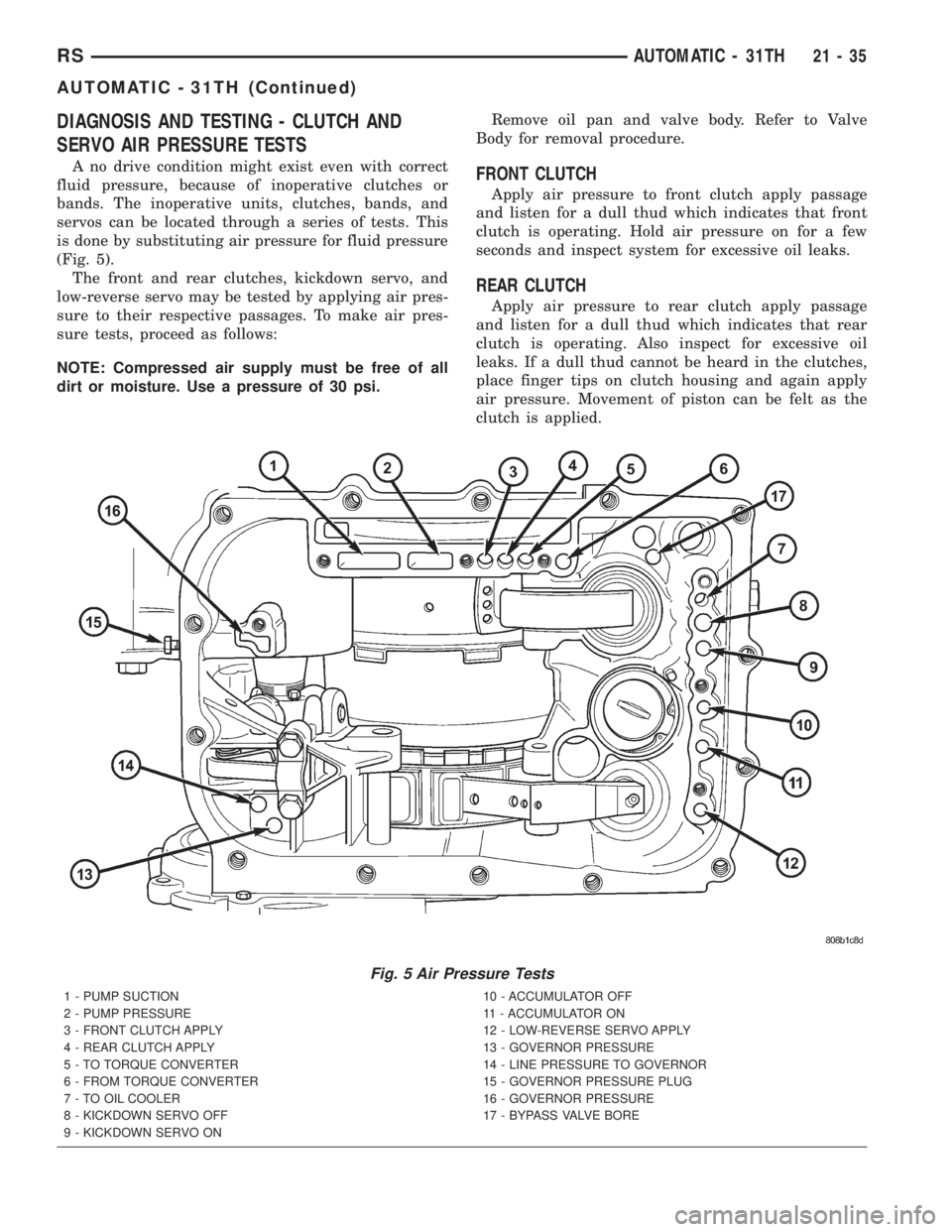
SERVO AIR PRESSURE TESTS
A no drive condition might exist even with correct
fluid pressure, because of inoperative clutches or
bands. The inoperative units, clutches, bands, and
servos can be located through a series of tests. This
is done by substituting air pressure for fluid pressure
(Fig. 5).
The front and rear clutches, kickdown servo, and
low-reverse servo may be tested by applying air pres-
sure to their respective passages. To make air pres-
sure tests, proceed as follows:
NOTE: Compressed air supply must be free of all
dirt or moisture. Use a pressure of 30 psi.Remove oil pan and valve body. Refer to Valve
Body for removal procedure.FRONT CLUTCH
Apply air pressure to front clutch apply passage
and listen for a dull thud which indicates that front
clutch is operating. Hold air pressure on for a few
seconds and inspect system for excessive oil leaks.
REAR CLUTCH
Apply air pressure to rear clutch apply passage
and listen for a dull thud which indicates that rear
clutch is operating. Also inspect for excessive oil
leaks. If a dull thud cannot be heard in the clutches,
place finger tips on clutch housing and again apply
air pressure. Movement of piston can be felt as the
clutch is applied.
Fig. 5 Air Pressure Tests
1 - PUMP SUCTION
2 - PUMP PRESSURE
3 - FRONT CLUTCH APPLY
4 - REAR CLUTCH APPLY
5 - TO TORQUE CONVERTER
6 - FROM TORQUE CONVERTER
7 - TO OIL COOLER
8 - KICKDOWN SERVO OFF
9 - KICKDOWN SERVO ON10 - ACCUMULATOR OFF
11 - ACCUMULATOR ON
12 - LOW-REVERSE SERVO APPLY
13 - GOVERNOR PRESSURE
14 - LINE PRESSURE TO GOVERNOR
15 - GOVERNOR PRESSURE PLUG
16 - GOVERNOR PRESSURE
17 - BYPASS VALVE BORE
RSAUTOMATIC - 31TH21-35
AUTOMATIC - 31TH (Continued)