relay CHRYSLER VOYAGER 2001 Service Manual
[x] Cancel search | Manufacturer: CHRYSLER, Model Year: 2001, Model line: VOYAGER, Model: CHRYSLER VOYAGER 2001Pages: 4284, PDF Size: 83.53 MB
Page 1913 of 4284
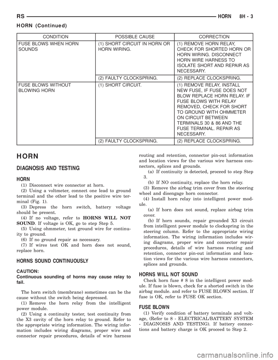
CONDITION POSSIBLE CAUSE CORRECTION
FUSE BLOWS WHEN HORN
SOUNDS(1) SHORT CIRCUIT IN HORN OR
HORN WIRING.(1) REMOVE HORN RELAY,
CHECK FOR SHORTED HORN OR
HORN WIRING. DISCONNECT
HORN WIRE HARNESS TO
ISOLATE SHORT AND REPAIR AS
NECESSARY.
(2) FAULTY CLOCKSPRING. (2) REPLACE CLOCKSPRING.
FUSE BLOWS WITHOUT
BLOWING HORN(1) SHORT CIRCUIT. (1) REMOVE RELAY, INSTALL
NEW FUSE, IF FUSE DOES NOT
BLOW REPLACE HORN RELAY. IF
FUSE BLOWS WITH RELAY
REMOVED, CHECK FOR SHORT
TO GROUND WITH OHMMETER
ON CIRCUIT BETWEEN
TERMINALS 30 & 86 AND THE
FUSE TERMINAL. REPAIR AS
NECESSARY.
(2) FAULTY CLOCKSPRING. (2) REPLACE CLOCKSPRING.
HORN
DIAGNOSIS AND TESTING
HORN
(1) Disconnect wire connector at horn.
(2) Using a voltmeter, connect one lead to ground
terminal and the other lead to the positive wire ter-
minal (Fig. 1).
(3) Depress the horn switch, battery voltage
should be present.
(4) If no voltage, refer toHORNS WILL NOT
SOUND. If voltage is OK, go to step Step 5.
(5) Using ohmmeter, test ground wire for continu-
ity to ground.
(6) If no ground repair as necessary.
(7) If wires test OK and horn does not sound,
replace horn.
HORNS SOUND CONTINUOUSLY
CAUTION:
Continuous sounding of horns may cause relay to
fail.
The horn switch (membrane) sometimes can be the
cause without the switch being depressed.
(1) Remove the horn relay from the intelligent
power module.
(2) Using a continuity tester, test continuity from
the X3 cavity of the horn relay to ground. Refer to
the appropriate wiring information. The wiring infor-
mation includes wiring diagrams, proper wire and
connector repair procedures, details of wire harnessrouting and retention, connector pin-out information
and location views for the various wire harness con-
nectors, splices and grounds.
(a) If continuity is detected, proceed to step Step
3.
(b) If NO continuity, replace the horn relay.
(3) Remove the airbag trim cover from the steering
wheel and disengage horn connector.
(4) Install horn relay into intelligent power mod-
ule.
(a) If horn does not sound, replace airbag trim
cover.
(b) If horn sounds, repair grounded X3 circuit
from intelligent power module to clockspring in the
steering column. Refer to the appropriate wiring
information. The wiring information includes wir-
ing diagrams, proper wire and connector repair
procedures, details of wire harness routing and
retention, connector pin-out information and loca-
tion views for the various wire harness connectors,
splices and grounds.HORNS WILL NOT SOUND
Check horn fuse#8intheintelligent power mod-
ule. If fuse is blown, check for a shorted switch in the
airbag module. and refer to FUSE BLOWN section. If
fuse is OK, refer to FUSE OK section.
FUSE BLOWN
(1) Verify condition of battery terminals and volt-
age, (Refer to 8 - ELECTRICAL/BATTERY SYSTEM
- DIAGNOSIS AND TESTING). If battery connec-
tions and battery charge is OK proceed to Step 2.
RSHORN8H-3
HORN (Continued)
Page 1914 of 4284
(2) Using a voltmeter, test for battery voltage at
both sides of horn fuse 7. If voltage is OK, on both
sides of fuse, proceed to Fuse OK. If voltage is OK,
on one side of fuse, the fuse is blown, proceed to Step
3.
(3) Using a suitable ammeter in place of the fuse,
test amperage draw of the horn circuit. If amperage
draw is greater than 20 amps without the horn
switch depressed, a grounded circuit exists between
the fuse and the horn relay. Proceed to Step 4. If
amperage draw is greater than 20 amps with the
horn switch depressed, a grounded circuit exists
between the horn relay and the horn. Proceed to step
Step 5.
(4) Remove the horn relay from the intelligent
power module. If the amperage draw drops to 0
amps, the horn switch or circuit is shorted. Refer to
the appropriate wiring information. The wiring infor-
mation includes wiring diagrams, proper wire and
connector repair procedures, details of wire harness
routing and retention, connector pin-out information
and location views for the various wire harness con-
nectors, splices and grounds. If the amperage draw
does not drop to 0 amps, repair short at the intelli-
gent power module.
(5) Disengage a wire connector from one of the
horns. If amperage drops and the connected horn
sounds, replace the faulty horn. If amperage does not
drop with both horns disconnected and the horn
switch depressed, proceed to Step 6.
(6) Using a continuity tester, with the horns dis-
connected test continuity of the X2 cavity of the horn
relay to ground. Refer to the appropriate wiring
information. The wiring information includes wiring
diagrams, proper wire and connector repair proce-
dures, details of wire harness routing and retention,
connector pin-out information and location views for
the various wire harness connectors, splices and
grounds. If continuity is detected, the circuit is
grounded between the Junction Block and the horns.
Locate and repair pinched harness.
FUSE OK
(1) Remove the horn relay from the intelligent
power module.
(2) Using a continuity tester, Depress horn switch
and test continuity from the X3 cavity of the horn
relay to ground. Refer to the appropriate wiring
information. The wiring information includes wiring
diagrams, proper wire and connector repair proce-
dures, details of wire harness routing and retention,
connector pin-out information and location views for
the various wire harness connectors, splices and
grounds.
(a) If continuity is detected, proceed to Step 3.
(b) If NO continuity, proceed to Step 4.(3) Using a suitable jumper wire, jump across the
fuse F62 cavity and the X2 cavity of the horn relay in
the Junction Block.
(a) If the horn sounds, replace the horn relay.
(b) If the horn does not sound, proceed to Step 4.
(4) Remove airbag trim cover from steering wheel.
Refer to ELECTRICAL, RESTRAINTS.
(5) Test continuity across horn switch connectors
with horn switch depressed.
(a) If continuity is detected, repair open circuit
between the relay and the horn switch.
(b) If NO continuity, replace airbag trim cover.
(6) Install horn relay into intelligent power mod-
ule.
(7) Disengage wire connectors from horns.
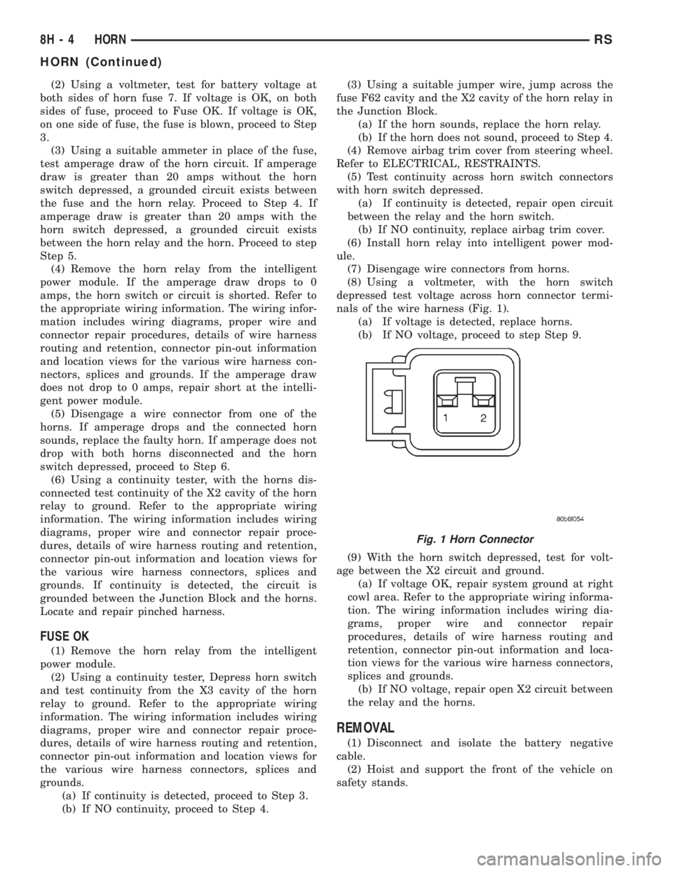
(8) Using a voltmeter, with the horn switch
depressed test voltage across horn connector termi-
nals of the wire harness (Fig. 1).
(a) If voltage is detected, replace horns.
(b) If NO voltage, proceed to step Step 9.
(9) With the horn switch depressed, test for volt-
age between the X2 circuit and ground.
(a) If voltage OK, repair system ground at right
cowl area. Refer to the appropriate wiring informa-
tion. The wiring information includes wiring dia-
grams, proper wire and connector repair
procedures, details of wire harness routing and
retention, connector pin-out information and loca-
tion views for the various wire harness connectors,
splices and grounds.
(b) If NO voltage, repair open X2 circuit between
the relay and the horns.
REMOVAL
(1) Disconnect and isolate the battery negative
cable.
(2) Hoist and support the front of the vehicle on
safety stands.
Fig. 1 Horn Connector
8H - 4 HORNRS
HORN (Continued)
Page 1915 of 4284
(3) From behind the front fascia and forward of
the left front wheel, disconnect the wire connectors
from horn.
(4) Remove the mounting bracket attaching nut
from the bottom of radiator closure panel. Do not
remove the horn from mounting bracket.
(5) Separate the horn(s) from vehicle.
INSTALLATION
(1) Install the horns to the vehicle.
(2) Install the mounting bracket nut.
(3) Reconnect the wire connectors to the horns.
(4) Lower the vehicle.
(5) Reconnect the battery negative cable.
HORN RELAY
DIAGNOSIS AND TESTING
(1) Remove horn relay.
(2) Using ohmmeter, test between relay connector
terminals 85 to 86 for 70 to 75 ohms resistance. If
resistance not OK, replace relay.
(3) Test for continuity between ground and termi-
nal 85 of horn relay.
(a) When the horn switch is not depressed, no
continuity should be present.
(b) Continuity to ground when horn switch is
depressed.
(c) If continuity is not correct repair horn
switch or wiring as necessary, refer to the appro-
priate wiring information. The wiring information
includes wiring diagrams, proper wire and connec-
tor repair procedures, details of wire harness rout-
ing and retention, connector pin-out information
and location views for the various wire harness
connectors, splices and grounds.
(4) Using voltmeter, test voltage at:
(a) Terminals 30 and 86 of the horn relay to
body ground.(b) If NO voltage check fuse 8 of the intelligent
power module.
(c) If incorrect voltage, repair as necessary. Refer
to the appropriate wiring information. The wiring
information includes wiring diagrams, proper wire
and connector repair procedures, details of wire
harness routing and retention, connector pin-out
information and location views for the various wire
harness connectors, splices and grounds.
(5) Insert a jumper wire between terminal 30 and
87 of the intelligent power module.
(a) If horn sounds replace relay.
(b) If the horn does not sound, install horn relay
and refer to Horn Test.
REMOVAL
(1) Disconnect and isolate the battery negative
cable.
(2) Remove cover from the intelligent power mod-
ule.
(3) Remove relay from intelligent power module.
INSTALLATION
(1) Push relay into intelligent power module.
(2) Install cover.
(3) Reconnect battery negative cable.
HORN SWITCH
DESCRIPTION
The horn switch is molded into the airbag trim
cover. The horn switch can not be serviced separately.
For service procedures, refer to ELECTRICAL /
RESTRAINTS.
RSHORN8H-5
HORN (Continued)
Page 1917 of 4284
IGNITION CONTROL
TABLE OF CONTENTS
page page
IGNITION CONTROL
DESCRIPTION............................1
OPERATION.............................1
SPECIFICATIONS.........................1
AUTO SHUT DOWN RELAY
DESCRIPTION............................3
OPERATION.............................3
CAMSHAFT POSITION SENSOR
DESCRIPTION............................3
OPERATION.............................3
REMOVAL...............................3
INSTALLATION............................5
IGNITION COIL
DESCRIPTION............................6
OPERATION.............................6REMOVAL...............................6
INSTALLATION............................6
KNOCK SENSOR
DESCRIPTION............................7
OPERATION.............................7
REMOVAL...............................7
INSTALLATION............................8
SPARK PLUG
DESCRIPTION............................8
REMOVAL...............................9
INSTALLATION............................9
SPARK PLUG CABLE
DESCRIPTION............................9
REMOVAL...............................9
INSTALLATION............................9
IGNITION CONTROL
DESCRIPTION - IGNITION SYSTEM
NOTE: All engines use a fixed ignition timing sys-
tem. Basic ignition timing is not adjustable. All
spark advance is determined by the Powertrain
Control Module (PCM).
The distributorless ignition system used on these
engines is referred to as the Direct Ignition System
(DIS). The system's three main components are the
coils, crankshaft position sensor, and camshaft posi-
tion sensor. The coil on plug ignition system utilizesan ignition coil for every cylinder, it is mounted
directly over the each spark plug.
OPERATION - IGNITION SYSTEM
The crankshaft position sensor and camshaft posi-
tion sensor are hall effect devices. The camshaft posi-
tion sensor and crankshaft position sensor generate
pulses that are inputs to the PCM. The PCM deter-
mines engine position from these sensors. The PCM
calculates injector sequence and ignition timing from
crankshaft & camshaft position. For a description of
both sensors, refer to Camshaft Position Sensor and
Crankshaft Position Sensor in this section.
SPECIFICATIONS
TORQUE
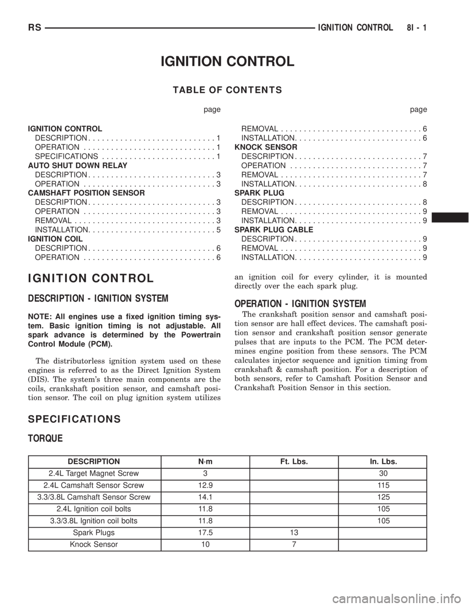
DESCRIPTION N´m Ft. Lbs. In. Lbs.
2.4L Target Magnet Screw 3 30
2.4L Camshaft Sensor Screw 12.9 115
3.3/3.8L Camshaft Sensor Screw 14.1 125
2.4L Ignition coil bolts 11.8 105
3.3/3.8L Ignition coil bolts 11.8 105
Spark Plugs 17.5 13
Knock Sensor 10 7
RSIGNITION CONTROL8I-1
Page 1919 of 4284
AUTO SHUT DOWN RELAY
DESCRIPTION
The relay is located in the Power Distribution Cen-
ter (PDC). For the location of the relay within the
PDC, refer to the PDC cover for location. Check elec-
trical terminals for corrosion and repair as necessary
OPERATION
The ASD sense circuit informs the PCM when the
ASD relay energizes. A 12 volt signal at this input
indicates to the PCM that the ASD has been acti-
vated. This input is used only to sense that the ASD
relay is energized.
When energized, the ASD relay supplies battery
voltage to the fuel injectors, ignition coils and the
heating element in each oxygen sensor. If the PCM
does not receive 12 volts from this input after
grounding the ASD relay, it sets a Diagnostic Trouble
Code (DTC).
When energized, the ASD relay provides power to
operate the injectors, ignition coil, generator field, O2
sensor heaters (both upstream and downstream), and
also provides a sense circuit to the PCM for diagnos-
tic purposes. The PCM energizes the ASD any time
there is a Crankshaft Position sensor signal that
exceeds a predetermined value. The ASD relay can
also be energized after the engine has been turned
off to perform an O2 sensor heater test, if vehicle is
equipped with OBD II diagnostics.
As mentioned earlier, the PCM energizes the ASD
relay during an O2 sensor heater test. This test is
performed only after the engine has been shut off.
The PCM still operates internally to perform several
checks, including monitoring the O2 sensor heaters.
CAMSHAFT POSITION
SENSOR
DESCRIPTION
The camshaft position sensorfor the 3.3/3.8L is
mounted in the front of the timing case cover (Fig. 7)
and the camshaft position sensor for the 2.4L is
mounted on the end of the cylinder head (Fig. 4).
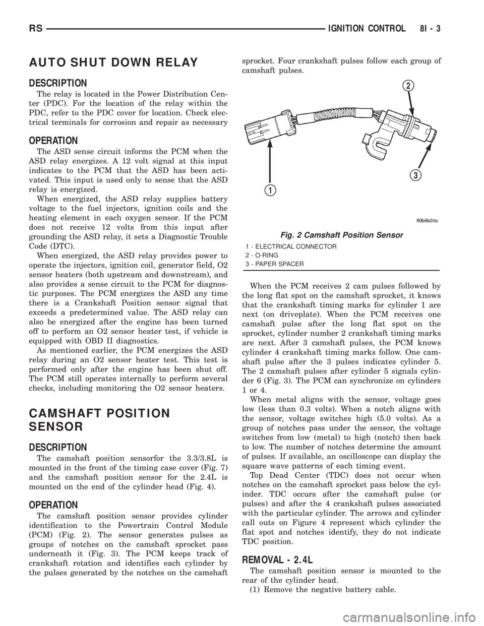
OPERATION
The camshaft position sensor provides cylinder
identification to the Powertrain Control Module
(PCM) (Fig. 2). The sensor generates pulses as
groups of notches on the camshaft sprocket pass
underneath it (Fig. 3). The PCM keeps track of
crankshaft rotation and identifies each cylinder by
the pulses generated by the notches on the camshaftsprocket. Four crankshaft pulses follow each group of
camshaft pulses.
When the PCM receives 2 cam pulses followed by
the long flat spot on the camshaft sprocket, it knows
that the crankshaft timing marks for cylinder 1 are
next (on driveplate). When the PCM receives one
camshaft pulse after the long flat spot on the
sprocket, cylinder number 2 crankshaft timing marks
are next. After 3 camshaft pulses, the PCM knows
cylinder 4 crankshaft timing marks follow. One cam-
shaft pulse after the 3 pulses indicates cylinder 5.
The 2 camshaft pulses after cylinder 5 signals cylin-
der 6 (Fig. 3). The PCM can synchronize on cylinders
1or4.
When metal aligns with the sensor, voltage goes
low (less than 0.3 volts). When a notch aligns with
the sensor, voltage switches high (5.0 volts). As a
group of notches pass under the sensor, the voltage
switches from low (metal) to high (notch) then back
to low. The number of notches determine the amount
of pulses. If available, an oscilloscope can display the
square wave patterns of each timing event.
Top Dead Center (TDC) does not occur when
notches on the camshaft sprocket pass below the cyl-
inder. TDC occurs after the camshaft pulse (or
pulses) and after the 4 crankshaft pulses associated
with the particular cylinder. The arrows and cylinder
call outs on Figure 4 represent which cylinder the
flat spot and notches identify, they do not indicate
TDC position.
REMOVAL - 2.4L
The camshaft position sensor is mounted to the
rear of the cylinder head.
(1) Remove the negative battery cable.
Fig. 2 Camshaft Position Sensor
1 - ELECTRICAL CONNECTOR
2 - O-RING
3 - PAPER SPACER
RSIGNITION CONTROL8I-3
Page 1922 of 4284

IGNITION COIL
DESCRIPTION
The ignition coil assembly consists of 2 or 3 inde-
pendent coils molded together (Fig. 10) or (Fig. 11).
The coil assembly for the 3.3/3.8L is mounted on the
intake manifold. The coil assembly for the 2.4L is
mounted on the cylinder head cover. Spark plug
cables route to each cylinder from the coil.
OPERATION
The coil fires two spark plugs every power stroke.
One plug is the cylinder under compression, the
other cylinder fires on the exhaust stroke. The Pow-
ertrain Control Module (PCM) determines which of
the coils to charge and fire at the correct time.
The Auto Shutdown (ASD) relay provides battery
voltage to the ignition coil. The PCM provides a
ground contact (circuit) for energizing the coil. When
the PCM breaks the contact, the magnetic energy in
the coil transfers to the secondary causing the spark.
The PCM will de-energize the ASD relay if it does
not receive the crankshaft position sensor and cam-
shaft position sensor inputs. Refer to Auto Shutdown
(ASD) RelayÐPCM Output, in this section for relay
operation.
REMOVAL - 2.4L
The electronic ignition coil pack attaches directly
to the valve cover.
(1) Diconnect the negative battery cable.
(2) Disconnect electrical connector from coil pack
(3) Remove coil pack mounting bolts.(4) Remove coil pack and heat shield (Fig. 10).
REMOVAL - 3.3/3.8L
(1) Disconnect the negative battery cable.
(2) Remove the throttle and speed control cables
from clip.
(3) Remove 2 bolts from the Power steering reser-
voir to intake manifold.
(4) Loosen the lower nut for the power steering
reservoir from stud on ignition coil bracket.
(5) Reposition the Power steering reservoir (Fig.
12).
(6) Remove the ignition cables from the ignition
coil.
(7) Disconnect the electrical connector from the
ignition coil.
(8) Remove 2 nuts from the ignition coil studs.
(9) Remove 2 bolts from ignition coil, remove coil.
INSTALLATION - 2.4L
(1) Install ignition coil and heat shield to valve
cover and tighten bolts.
(2) Connect the electrical connector to the ignition
coil.
(3) Transfer spark plug cables to new coil pack.
The coil pack towers are numbered with the cylinder
identification. Be sure the ignition cables are fully
seated onto the towers.
(4) Connect the negative battery cable.
Fig. 10 IGNITION COIL - 2.4L
Fig. 11 IGNITION COIL - 3.3/3.8L
1 - IGNITION COIL
8I - 6 IGNITION CONTROLRS
Page 1943 of 4284
DAYTIME RUNNING LAMPS
Power is reduced using pulse-width modulation to
the high beams, where by the power is switched on
and off rapidly instead of remaining on continuously.
The duration and interval of the power pulses is pro-
grammed into the Front Control Module (FCM).
HEADLAMP SYSTEM
The headlamp system will default to headlamps
ON position when ignition switch is ON and when an
open or short circuit failure occurs on the headlamp
switch input. The system will return to normal oper-
ation when the open or short is repaired. A fault will
be reported by the BCM when a failure occurs on the
dimmer or headlamp switch input.
If the exterior lamps are ON and the headlamp
switch is in any position other than OFF or AUTO
and with the ignition switch OFF (LOCK) after 3
minutes the BCM sends a message via J1850 to the
FCM informing the FCM to turn off the headlamps,
park lamps and fog lamps. This feature prevents the
vehicle battery from being discharged when the vehi-
cle lights have been left ON.
HEADLAMP TIME DELAY SYSTEM
The headlamp time delay system is activated by
turning the headlamps ON (high or low beam) while
the engine is running, turning the ignition switch
OFF, and then turning the headlamp switch OFF
within 45 seconds. The system will not activate if
more than 45 seconds elapse between ignition switch
OFF and headlamp switch OFF. The BCM will allow
the headlamps to remain ON for 90 seconds (config-
urable) before they automatically turn off (If the key
is in the ignition during the headlamp time delay
mode, then both the headlamps and park lamps
(including panel dimming) will be ON). Refer to the
Owner's Manual for more information.
If the headlamp switch is in the Auto Headlamp
Position, the headlamps are ON due to the night sig-
nal from the CMTC and the ignition switch is in any
position other than run/start, the BCM shall enter a
90 second (configurable) Auto Headlamps time delay
mode. If the key is in the ignition during the head-
lamp time delay mode, then both the headlamps and
park lamps (including panel dimming) will be ON. If
the key is not in the ignition, then only the head-
lamps will be ON. The BCM will allow the head-
lamps to remain ON for 90 seconds before they
automatically turn OFF. Refer to the Owner's Man-
ual for more information.
LAMP OUTAGE
If one or more of the following lamps (Low and/or
High beams) are out, then a ªlamps outº indicator
located in the cluster will illuminate.
OPTICAL HORN/HIGH BEAMS
When the multifunction switch is pulled to the first
detent (optical horn) signal, the headlamps are ON,
key-in the ignition the BCM shall send a message via
J1850 to the FCM to turn on the headlamps drivers
to illuminate all four filaments (Low and High
beams). When the multifunction switch is pulled to
the second detent (high beam) signal and the head-
lamps are ON, the BCM shall send a message via
J1850 to the FCM to turn on the headlamps drivers.
The High Beams are illuminated and the Low Beams
and Fog Lamps (if ON) are extinguished. If the head-
lamps were in the high beam configuration when
power was removed from the headlamps, the head-
lamps will be configured as low beam the next time
they are activated.
DIAGNOSIS AND TESTING
WARNING: EYE PROTECTION SHOULD BE USED
WHEN SERVICING GLASS COMPONENTS. PER-
SONAL INJURY CAN RESULT.
CAUTION: Do not touch the glass of halogen bulbs
with fingers or other possibly oily surface, reduced
bulb life will result. Do not use bulbs other than
those indicated in the Bulb Application table. Dam-
age to lamp and/or Daytime Running Lamp Module
can result. Do not use fuses, circuit breakers or
relays having greater amperage value than indi-
cated on the fuse panel or in the Owners Manual.
When a vehicle experiences problems with the
headlamp system, verify the condition of the battery
connections, fuses, charging system, headlamp bulbs,
wire connectors, relay, high beam switch, dimmer
switch, and headlamp switch. Refer to the appropri-
ate wiring information. The wiring information
includes wiring diagrams, proper wire and connector
repair procedures, details of wire harness routing
and retention, connector pin-out information and
location views for the various wire harness connec-
tors, splices and grounds.
Each vehicle is equipped with various lamp assem-
blies. A good ground is necessary for proper lighting
operation. Grounding is provided by the lamp socket
when it comes in contact with the metal body, or
through a separate ground wire.
When changing lamp bulbs check the socket for
corrosion. If corrosion is present, clean it with a wire
brush.
When it is necessary to remove components to ser-
vice another, it should not be necessary to apply
excessive force or bend a component to remove it.
Before damaging a trim component, verify hidden
fasteners or captured edges are not holding the com-
ponent in place.
RSLAMPS/LIGHTING - EXTERIOR8L-3
LAMPS/LIGHTING - EXTERIOR (Continued)
Page 1946 of 4284

CONDITION POSSIBLE CAUSES CORRECTION
3. Faulty fog lamp switch (part of
headlamp switch).3. Replace headlamp switch.
4. Loose or corroded terminals or
splices in circuit.4. Inspect and repair all connectors and
splices. Refer to Electrical, Wiring
Information.
5. Is relay engaging properly? 5. Verify function of fog lamp relay in IPM.
6. J1850 Bus Communication. 6. Verify J1850 message (fog lamp info)
transmitted from BCM and received by
FCM.
FOG LAMPS DO NOT
ILLUMINATE1. Blown fuse for fog lamp. 1. Replace fuse. Refer to Electrical, Wiring
Information.
2. No Z349/Z248 ground at fog
lamps.2. Repair circuit ground. Refer to Electrical,
Wiring Information.
3. Faulty fog lamp switch (part of
headlamp switch).3. Replace headlamp switch.
4. Broken connector terminal or wire
splice in fog lamp circuit.4. Repair connector terminal or wire splice.
5. Faulty or burned out bulb. 5. Replace bulb.
6. Is relay engaging? 6. Verify function of fog lamp relay in IPM.
7. J1850 Bus Communication. 7. Verify J1850 message (fog lamp info)
transmitted from BCM and received by
FCM.
DAYTIME RUNNING LAMP (CANADA ONLY)
CONDITION POSSIBLE CAUSES CORRECTION
DAYTIME RUNNING
LAMPS DO NOT
WORK
1. Parking brake engaged. 1. Disengage parking brake.
2. Parking brake circuit shorted to
ground.2. Check cluster telltale, refer to the appropriate
wiring information. The wiring information
includes wiring diagrams, proper wire and
connector repair procedures, further details on
wire harness routing and retention, as well as
pin-out and location views for the various wire
harness connectors, splices and grounds.
3. Headlamp circuit shorted to ground. 3. Refer to the appropriate wiring information.
The wiring information includes wiring
diagrams, proper wire and connector repair
procedures, further details on wire harness
routing and retention, as well as pin-out and
location views for the various wire harness
connectors, splices and grounds.
4. Faulty DRL relay. 4. Replace DRL relay.
5. Body controller not programed with
Canadian country code.5. Check country code.
8L - 6 LAMPS/LIGHTING - EXTERIORRS
LAMPS/LIGHTING - EXTERIOR (Continued)
Page 2031 of 4284
trically and independently using the separate power
seat switches found on the outboard seat cushion
side shield of each front seat. See the owner's manual
in the vehicle glove box for more information on the
features, use and operation of the power seat system.
OPERATION - MEMORY SYSTEM
The Memory Seat/Mirror Module (MSMM) will
drive a maximum of 2 motors at a time in a given
direction. If conflicting directions are requested, the
priority for response will be as follows:
²Seat Track Rearward
²Seat Front Down
²Seat Rear Down
²Recliner Rearward
²Seat Track Forward
²Seat Front Up
²Seat Rear Up
²Recliner Forward
The inputs from these switches to the MSMM is a
current limited battery source fed by the MSMM.
This protects the MSMM printed circuit board traces
from acting as fuses. All of these switch contact
inputs to the MSMM are normally closed to ground,
except when actuated.
Soft stops are incorporated to prevent the motor
from being driven into a stall. Should the seat have
restricted travel, refer to Resetting Soft Stops in this
section.
See the owner's manual in the vehicle glove box for
more information on the features, use and operation
of the memory system. For diagnosis of the MSM, the
PCI data bus, or the other electronic modules on the
PCI data bus that provide inputs and outputs for the
memory system, the use of a DRBtscan tool and the
proper Diagnostic Procedures manual are recom-
mended.
ELECTRONIC VEHICLE INFORMATION CENTER
The Electronic Vehicle Information Center (EVIC)
serves as the user interface for the memory system.
It displays memory system status messages and pro-
vides the user with the means for enabling and dis-
abling the many customer programmable features
available on the vehicle, including those for the mem-
ory system.
See the owner's manual in the vehicle glove box for
more information on the features, use and operation
of the EVIC. Refer toElectronic Vehicle Informa-
tion Centerin Overhead Console Systems for more
information on the EVIC.
DIAGNOSIS AND TESTING - POWER SEAT
SYSTEM
Following are tests that will help to diagnose the
hard wired components and circuits of the power seatsystem. However, if the vehicle is also equipped with
the optional memory system, these tests may not
prove conclusive in the diagnosis of the driver side
power seat. In order to obtain conclusive testing of
the driver side power seat with the memory system
option, the Programmable Communications Interface
(PCI) data bus network and all of the electronic mod-
ules that provide inputs to, or receive outputs from
the memory system components must be checked.
The most reliable, efficient, and accurate means to
diagnose the driver side power seat with the memory
system option requires the use of a DRBtscan tool
and the proper Diagnostic Procedures manual. The
DRBtscan tool can provide confirmation that the
PCI data bus is functional, that all of the electronic
modules are sending and receiving the proper mes-
sages on the PCI data bus, and that the memory sys-
tem is receiving the proper hard wired inputs and
relaying the proper hard wired outputs to perform its
driver side power seat functions.
WARNING: SOME VEHICLES ARE EQUIPPED WITH
SEATBACK MOUNTED AIRBAGS (Fig. 1). BEFORE
ATTEMPTING TO DIAGNOSE OR SERVICE ANY
SEAT OR POWER SEAT SYSTEM COMPONENT
YOU MUST FIRST DISCONNECT AND ISOLATE THE
BATTERY NEGATIVE CABLE. THEN WAIT TWO MIN-
UTES FOR THE SYSTEM CAPACITOR TO DIS-
CHARGE BEFORE FURTHER SYSTEM SERVICE.
THIS IS THE ONLY SURE WAY TO DISABLE THE
AIRBAG SYSTEM. FAILURE TO DO SO COULD
RESULT IN ACCIDENTAL AIRBAG DEPLOYMENT
AND POSSIBLE PERSONAL INJURY.
Before any testing of the power seat system is
attempted, the battery should be fully-charged and
all of the power seat system wire harness connections
and pins cleaned and tightened to ensure proper cir-
cuit continuity and ground paths. For complete cir-
cuit diagrams, refer toPower Seatin Wiring
Diagrams.
With the dome lamp on, apply the power seat
switch in the direction of the failure. If the dome
lamp dims, the seat may be jamming. Check under
and behind the seat for binding or obstructions. If
the dome lamp does not dim, proceed with testing of
the individual components and circuits.
DIAGNOSIS AND TESTING - MEMORY SYSTEM
CHECK AND RESET SOFT STOPS
To check and reset the power memory seat soft
stops, use the power seat control switches to move
the seat in one direction to the end of travel, allow a
couple of seconds before re-energizing the seat in the
same direction until it stops and for three additional
seconds after it stops. (The amount the seat moved
RSPOWER SEATS8N-51
POWER SEATS (Continued)
Page 2032 of 4284
upon the second energizing is the amount the soft
stops have been reprogrammed.
Repeat this procedure for each direction of seat
movement (One at a time).
NOTE: Checking and resetting of the power mem-
ory seat soft stops will not affect the customer's
programmed positions.
DIAGNOSIS AND TESTING MEMORY SYSTEM
In order to obtain conclusive testing of the memory
system, the Programmable Communications Interface
(PCI) data bus network and all of the electronic mod-
ules that provide inputs to, or receive outputs from
the memory system components must be checked.
The most reliable, efficient, and accurate means to
diagnose the memory system requires the use of a
DRB IIItscan tool and the proper Diagnostic Proce-
dures manual. The DRB IIItscan tool can provide
confirmation that the PCI data bus is functional, that
all of the electronic modules are sending and receiv-
ing the proper messages on the PCI data bus, and
that the memory system is receiving the proper hard
wired inputs and relaying the proper hard wired out-
puts to perform its functions.
Following are diagnostic routines that are built
into the module which can be performed without the
use of a diagnostic scan tool. Refer to Wiring Dia-
grams for complete circuit schematic or connector
pin-out information.
DIAGNOSTIC MODE 1
Diagnostic Mode 1 clears soft limits and sets mem-
ory selector switches (1 and 2) to predetermined val-
ues.
ACTIVATION-Press and hold the S and 1 buttons
for 5 seconds to enter diagnostic mode 1. This mode
is exited at the completion of the mode 1 tasks or
upon grounding the DATA G87 circuit input to the
module.
Mode 1 will:
²Clear all soft limits to their default hard limit
values
²Load memory 1 with default settings corre-
sponding to horizontal rearward, front down, rear
down, and recliner rearward positions
²Load memory 2 with default settings corre-
sponding to horizontal forward, front up, rear up,
and recliner forward positions
DIAGNOSTIC MODE 2
Diagnostic mode 2 provides a way to determine if
the seat/mirror motors and position sensors are con-
nected properly.
ACTIVATION-Press and hold the S and 2 buttons
for 5 seconds to enter diagnostic mode 2. This modeis exited after 5 seconds of switch inactivity or upon
grounding the DATA G87 circuit input by moving the
transmission out of the PARK position.
Mode 2 will:
²Place the seat and mirror motors at their mid-
point
²When a single axis of seat or mirror motion is
requested by pressing a switch, the corresponding
motor is energized. This tests switch input and motor
output
DRIVER SEAT SWITCH
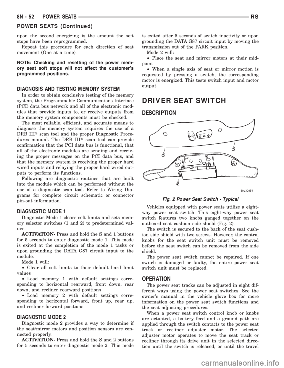
DESCRIPTION
Vehicles equipped with power seats utilize a eight-
way power seat switch. This eight-way power seat
switch features two knobs ganged together on the
outboard seat cushion side shield (Fig. 2).
The switch is secured to the back of the seat cush-
ion side shield with two screws. However, the control
knobs for the seat switch unit must be removed
before the seat switch can be removed from the side
shield.
The power seat switch cannot be repaired. If one
switch is damaged or faulty, the entire power seat
switch unit must be replaced.
OPERATION
The power seat tracks can be adjusted in eight dif-
ferent ways using the power seat switches. See the
owner's manual in the vehicle glove box for more
information on the power seat switch functions and
the seat adjusting procedures.
When a power seat switch control knob or knobs
are actuated, a battery feed and a ground path are
applied through the switch contacts to the power seat
track or recliner adjuster motor. The selected
adjuster motor operates to move the seat track or
recliner through its drive unit in the selected direc-
tion until the switch is released, or until the travel
Fig. 2 Power Seat Switch - Typical
8N - 52 POWER SEATSRS
POWER SEATS (Continued)