CD changer CHRYSLER VOYAGER 2001 Owner's Manual
[x] Cancel search | Manufacturer: CHRYSLER, Model Year: 2001, Model line: VOYAGER, Model: CHRYSLER VOYAGER 2001Pages: 4284, PDF Size: 83.53 MB
Page 1810 of 4284
CD CHANGER
DESCRIPTION
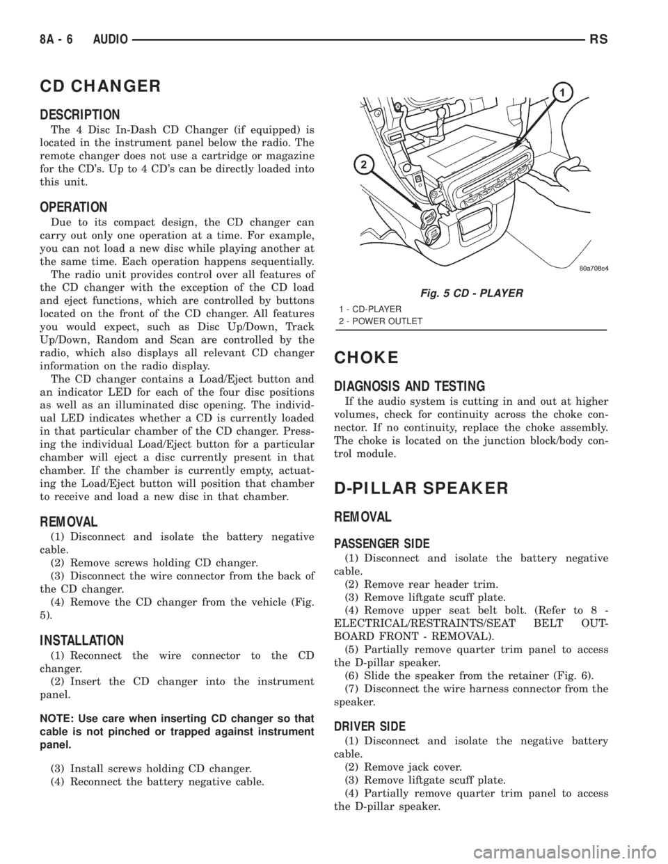
The 4 Disc In-Dash CD Changer (if equipped) is
located in the instrument panel below the radio. The
remote changer does not use a cartridge or magazine
for the CD's. Up to 4 CD's can be directly loaded into
this unit.
OPERATION
Due to its compact design, the CD changer can
carry out only one operation at a time. For example,
you can not load a new disc while playing another at
the same time. Each operation happens sequentially.
The radio unit provides control over all features of
the CD changer with the exception of the CD load
and eject functions, which are controlled by buttons
located on the front of the CD changer. All features
you would expect, such as Disc Up/Down, Track
Up/Down, Random and Scan are controlled by the
radio, which also displays all relevant CD changer
information on the radio display.
The CD changer contains a Load/Eject button and
an indicator LED for each of the four disc positions
as well as an illuminated disc opening. The individ-
ual LED indicates whether a CD is currently loaded
in that particular chamber of the CD changer. Press-
ing the individual Load/Eject button for a particular
chamber will eject a disc currently present in that
chamber. If the chamber is currently empty, actuat-
ing the Load/Eject button will position that chamber
to receive and load a new disc in that chamber.
REMOVAL
(1) Disconnect and isolate the battery negative
cable.
(2) Remove screws holding CD changer.
(3) Disconnect the wire connector from the back of
the CD changer.
(4) Remove the CD changer from the vehicle (Fig.
5).
INSTALLATION
(1) Reconnect the wire connector to the CD
changer.
(2) Insert the CD changer into the instrument
panel.
NOTE: Use care when inserting CD changer so that
cable is not pinched or trapped against instrument
panel.
(3) Install screws holding CD changer.
(4) Reconnect the battery negative cable.
CHOKE
DIAGNOSIS AND TESTING
If the audio system is cutting in and out at higher
volumes, check for continuity across the choke con-
nector. If no continuity, replace the choke assembly.
The choke is located on the junction block/body con-
trol module.
D-PILLAR SPEAKER
REMOVAL
PASSENGER SIDE
(1) Disconnect and isolate the battery negative
cable.
(2) Remove rear header trim.
(3) Remove liftgate scuff plate.
(4) Remove upper seat belt bolt. (Refer to 8 -
ELECTRICAL/RESTRAINTS/SEAT BELT OUT-
BOARD FRONT - REMOVAL).
(5) Partially remove quarter trim panel to access
the D-pillar speaker.
(6) Slide the speaker from the retainer (Fig. 6).
(7) Disconnect the wire harness connector from the
speaker.
DRIVER SIDE
(1) Disconnect and isolate the negative battery
cable.
(2) Remove jack cover.
(3) Remove liftgate scuff plate.
(4) Partially remove quarter trim panel to access
the D-pillar speaker.
Fig. 5 CD - PLAYER
1 - CD-PLAYER
2 - POWER OUTLET
8A - 6 AUDIORS
Page 1814 of 4284
REMOTE SWITCHES
DESCRIPTION
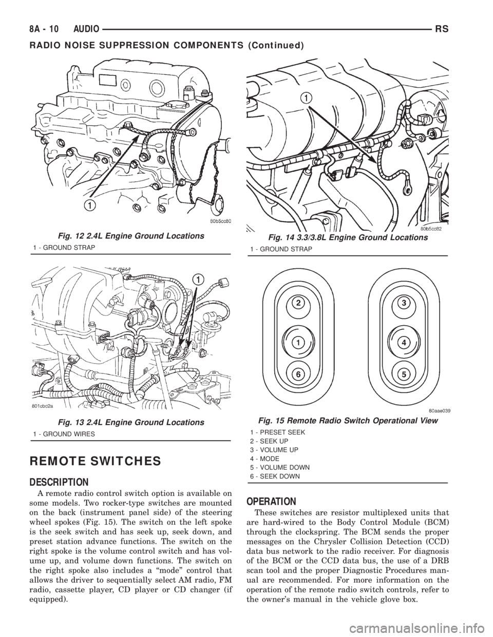
A remote radio control switch option is available on
some models. Two rocker-type switches are mounted
on the back (instrument panel side) of the steering
wheel spokes (Fig. 15). The switch on the left spoke
is the seek switch and has seek up, seek down, and
preset station advance functions. The switch on the
right spoke is the volume control switch and has vol-
ume up, and volume down functions. The switch on
the right spoke also includes a ªmodeº control that
allows the driver to sequentially select AM radio, FM
radio, cassette player, CD player or CD changer (if
equipped).
OPERATION
These switches are resistor multiplexed units that
are hard-wired to the Body Control Module (BCM)
through the clockspring. The BCM sends the proper
messages on the Chrysler Collision Detection (CCD)
data bus network to the radio receiver. For diagnosis
of the BCM or the CCD data bus, the use of a DRB
scan tool and the proper Diagnostic Procedures man-
ual are recommended. For more information on the
operation of the remote radio switch controls, refer to
the owner's manual in the vehicle glove box.
Fig. 12 2.4L Engine Ground Locations
1 - GROUND STRAP
Fig. 13 2.4L Engine Ground Locations
1 - GROUND WIRES
Fig. 14 3.3/3.8L Engine Ground Locations
1 - GROUND STRAP
Fig. 15 Remote Radio Switch Operational View
1 - PRESET SEEK
2 - SEEK UP
3 - VOLUME UP
4 - MODE
5 - VOLUME DOWN
6 - SEEK DOWN
8A - 10 AUDIORS
RADIO NOISE SUPPRESSION COMPONENTS (Continued)
Page 2099 of 4284

8W-02 COMPONENT INDEX
Component Page
A/C Compressor Clutch Relay........... 8Wa-42
A/C Compressor Clutch................ 8Wa-42
A/C-Heater Control................... 8Wa-42
A/C Pressure Sensor.................. 8Wa-42
Accelerator Pedal Position Sensor........ 8Wa-30
Accessory Relay...................... 8Wa-10
Airbags............................. 8Wa-43
Ambient Temp Sensor................. 8Wa-49
Antenna............................ 8Wa-47
ATC Remote Sensor................... 8Wa-42
Auto Shut Down Relay................. 8Wa-30
Auto Temp Control.................... 8Wa-42
Automatic Day/Night Mirror............ 8Wa-49
Autostick Switch..................... 8Wa-31
Back-Up Lamp Switch................. 8Wa-51
Battery Temperature Sensor............ 8Wa-20
Battery............................. 8Wa-20
Blend Door Actuators.................. 8Wa-42
Blower Motor Resistor................. 8Wa-42
Body Control Module.................. 8Wa-45
Boost Pressure Sensor................. 8Wa-30
B-Pillar Switches..................... 8Wa-61
Brake Fluid Level Switch............... 8Wa-40
Brake Lamp Switch................... 8Wa-51
Brake Transmission Shift Interlock
Solenoid.......................... 8Wa-31
Cabin Heater Assist................... 8Wa-30
Camshaft Position Sensor.............. 8Wa-30
CD Changer......................... 8Wa-47
Center High Mounted Stop Lamp........ 8Wa-51
Cinch/Release Motors.................. 8Wa-61
Clockspring................. 8Wa-33, 41, 43, 47
Clutch Pedal Interlock Switch Jumper..... 8Wa-10
Clutch Pedal Interlock Switch........... 8Wa-10
Clutch Pedal Upstop Switch............. 8Wa-30
Combination Relays................... 8Wa-54
Controller Antilock Brake.............. 8Wa-35
Crank Case Ventilation Heater.......... 8Wa-30
Crankshaft Position Sensor............. 8Wa-30
Cylinder Lock Switches................ 8Wa-39
Data Link Connector.................. 8Wa-18
Defogger Relay....................... 8Wa-48
Diagnostic Junction Port............... 8Wa-18
Dome Lamps........................ 8Wa-44
Door Ajar Switches.................... 8Wa-39
Door Courtesy Lamps.................. 8Wa-44
Door Lock Motor/Ajar Switches.......... 8Wa-61
Door Lock Switches................... 8Wa-61
Dosing Pump........................ 8Wa-30
Driver Heated Seat Module............. 8Wa-63
ECM/PCM Relay..................... 8Wa-30
EGR Solenoid........................ 8Wa-30Component Page
Electric Wiper De-Icer................. 8Wa-48
Engine Control Module................ 8Wa-30
Engine Coolant Temp Sensor............ 8Wa-30
Engine Oil Pressure Sensor............. 8Wa-30
Engine Oil Pressure Switch............. 8Wa-30
Engine Oil Temperature Sensor.......... 8Wa-30
EVAP/Purge Solenoid.................. 8Wa-30
Evaporator Temperature Sensor......... 8Wa-42
Floor Console Lamp................... 8Wa-44
Floor Console Power Outlet............. 8Wa-41
Fog Lamps.......................... 8Wa-50
Front Blower Module.................. 8Wa-42
Front Blower Motor Relay.............. 8Wa-42
Front Blower Motor................... 8Wa-42
Front Cigar Lighter................... 8Wa-41
Front Control Module.................. 8Wa-10
Front Fog Lamp Relay................. 8Wa-50
Front Intrusion Sensor................. 8Wa-39
Front Reading Lamps/Switch............ 8Wa-44
Front Washer Pump Motor.............. 8Wa-53
Front Wiper Hi/Low Relay.............. 8Wa-53
Front Wiper On/Off Relay.............. 8Wa-53
Fuel Heater Relay.................... 8Wa-10
Fuel Heater......................... 8Wa-30
Fuel Injectors........................ 8Wa-30
Fuel Pressure Sensor.................. 8Wa-30
Fuel Pressure Solenoid................. 8Wa-30
Fuel Pump Module.................... 8Wa-30
Fuel Pump Relay..................... 8Wa-30
Full Open Switches................... 8Wa-61
Fuselink............................ 8Wa-10
Fuses (IPM)......................... 8Wa-10
Generator........................... 8Wa-20
Glove Box Lamp...................... 8Wa-44
Glow Plug Relay...................... 8Wa-30
Glow Plugs.......................... 8Wa-30
Grounds............................ 8Wa-15
Halo Lamp.......................... 8Wa-44
Headlamp Leveling Motors............. 8Wa-50
Headlamp Switch..................... 8Wa-50
Headlamp Washer Pump Motor.......... 8Wa-53
Headlamp Washer Relay............... 8Wa-53
Headlamps.......................... 8Wa-50
Heated Seat Backs.................... 8Wa-63
Heated Seat Cushions................. 8Wa-63
High Beam Lamps.................... 8Wa-50
Hood Ajar Switch..................... 8Wa-39
Horn Relay.......................... 8Wa-41
Horn Switch......................... 8Wa-41
Horns.............................. 8Wa-41
Idle Air Control Motor................. 8Wa-30
Ignition Coil......................... 8Wa-30
RG8W-02 COMPONENT INDEX8Wa-02-1
Page 2189 of 4284

8W-18 BUS COMMUNICATIONS
Component Page
A/C-Heater Control.................. 8Wa-18-4
Auto Temp Control.................. 8Wa-18-4
Battery........................... 8Wa-18-2
Battery........................... 8Wa-18-3
Body Control Module............. 8Wa-18-2, 3, 4
Cabin Heater Assist................. 8Wa-18-3
CD Changer....................... 8Wa-18-4
Controller Antilock Brake............. 8Wa-18-4
Data Link Connector............. 8Wa-18-2, 3, 4
Diagnostic Junction Port........ 8Wa-18-2, 3, 4, 5
Engine Control Module............. 8Wa-18-3, 5
Front Control Module............ 8Wa-18-2, 3, 4
G100........................... 8Wa-18-2, 3
G101........................... 8Wa-18-2, 3
G300........................... 8Wa-18-2, 3
Instrument Cluster.................. 8Wa-18-4Component Page
Intelligent Power Module......... 8Wa-18-2, 3, 4
Left Side Impact Airbag Control Module . . 8Wa-18-5
Left Sliding Door Control Module....... 8Wa-18-5
Memory Seat/ Mirror Module.......... 8Wa-18-5
Occupant Restraint Controller......... 8Wa-18-4
Overhead Console................... 8Wa-18-4
Power Liftgate Module............... 8Wa-18-5
Powertrain Control Module.......... 8Wa-18-2, 5
PTC7 .......................... 8Wa-18-2, 3
Radio............................. 8Wa-18-4
Right Side Impact Airbag Control
Module......................... 8Wa-18-5
Right Sliding Door Control Module...... 8Wa-18-5
Sentry Key Immobilizer Module........ 8Wa-18-5
Thatcham Alarm Module.......... 8Wa-18-2, 3, 5
Transmission Control Module........ 8Wa-18-2, 4
RG8W-18 BUS COMMUNICATIONS8Wa-18-1
Page 2339 of 4284
8W-47 AUDIO SYSTEM
Component Page
Accessory Relay................... 8Wa-47-2, 5
Antenna.......................... 8Wa-47-5
Body Control Module............. 8Wa-47-2, 5, 6
CD Changer...................... 8Wa-47-10
Clockspring........................ 8Wa-47-6
Diagnostic Junction Port............ 8Wa-47-2, 5
Front Cigar Lighter................ 8Wa-47-2, 5
Front Control Module.............. 8Wa-47-2, 5
Fuse 5 (IPM)..................... 8Wa-47-2, 5
Fuse 14 (IPM).................... 8Wa-47-2, 5
Intelligent Power Module........... 8Wa-47-2, 5
Left Door Speaker............... 8Wa-47-3, 7, 8
Left Instrument Panel Speaker....... 8Wa-47-3, 7
Left Rear Pillar Speaker.............. 8Wa-47-9
Left Rear Speaker............... 8Wa-47-4, 5, 9
Left Remote Radio Switch............. 8Wa-47-6
Name Brand Speaker Relay........... 8Wa-47-5
Radio.............. 8Wa-47-2, 3, 4, 5, 6, 8, 9, 10
Radio Choke....................... 8Wa-47-5
Right Door Speaker.............. 8Wa-47-3, 7, 8
Right Instrument Panel Speaker...... 8Wa-47-3, 7
Right Rear Pillar Speaker............. 8Wa-47-9
Right Rear Speaker.............. 8Wa-47-4, 5, 9
Right Remote Radio Switch............ 8Wa-47-6
RG8W-47 AUDIO SYSTEM8Wa-47-1
Page 2442 of 4284
Component Page
C326............................. 8W-80-41
C327............................. 8W-80-41
C327............................. 8W-80-41
C329 (Diesel)....................... 8W-80-42
C329 (Diesel)....................... 8W-80-42
C330 (Diesel)....................... 8W-80-42
C330 (Diesel)....................... 8W-80-42
C331 (Diesel)....................... 8W-80-42
C331 (Diesel)....................... 8W-80-43
C332 (ATC)........................ 8W-80-43
C332 (ATC)........................ 8W-80-43
Cabin Heater Assist C1 (Diesel)........ 8W-80-43
Cabin Heater Assist C2 (Diesel)........ 8W-80-44
Camshaft Position Sensor (Gas)........ 8W-80-44
Camshaft Position Sensor (Diesel)...... 8W-80-44
CD Changer....................... 8W-80-44
Center Dome Lamp (Base/High Line).... 8W-80-45
Center High Mounted Stop Lamp....... 8W-80-45
Clockspring C1..................... 8W-80-45
Clockspring C2..................... 8W-80-45
Clockspring C3..................... 8W-80-45
Clockspring C4..................... 8W-80-46
Clockspring C5..................... 8W-80-46
Clutch Departure Switch (Diesel)....... 8W-80-46
Clutch Interlock/Upstop Switch (MTX) . . . 8W-80-46
Controller Antilock Brake............. 8W-80-47
Crank Case Ventilation Heater (Diesel) . . 8W-80-47
Crankshaft Position Sensor (Diesel)..... 8W-80-48
Crankshaft Position Sensor (Gas)....... 8W-80-48
Data Link Connector................. 8W-80-48
Diagnostic Junction Port.............. 8W-80-49
Dosing Pump....................... 8W-80-49
Driver Airbag C1.................... 8W-80-49
Driver Airbag C2.................... 8W-80-49
Driver Blend Door Actuator (ATC)...... 8W-80-50
Driver Blend Door Actuator (MTC)...... 8W-80-50
Driver Door Courtesy Lamp........... 8W-80-50
Driver Door Lock Switch.............. 8W-80-50
Driver Heated Seat Back............. 8W-80-50
Driver Heated Seat Cushion........... 8W-80-51
Driver Heated Seat Module C1......... 8W-80-51
Driver Heated Seat Module C2......... 8W-80-51
Driver Heated Seat Module C3......... 8W-80-51
Driver Power Seat Front Riser Motor.... 8W-80-52
Driver Power Seat Horizontal Motor..... 8W-80-52
Driver Power Seat Rear Riser Motor.... 8W-80-52
Driver Power Seat Recliner Motor...... 8W-80-52
Driver Power Seat Switch............. 8W-80-52
Driver Power Window Motor........... 8W-80-53
Driver Power Window Switch (LHD)..... 8W-80-53
Driver Power Window Switch (RHD).... 8W-80-53
Driver Seat Belt Switch.............. 8W-80-54
Driver Seat Belt Tensioner............ 8W-80-54
EGR Solenoid (Diesel)................ 8W-80-54Component Page
EGR Solenoid (Gas)................. 8W-80-54
Electric Wiper De-Icer C1............. 8W-80-54
Electric Wiper De-Icer C2............. 8W-80-55
Engine Control Module C1 (Diesel)...... 8W-80-55
Engine Control Module C2 (Diesel)...... 8W-80-57
Engine Coolant Temp Sensor (Diesel).... 8W-80-57
Engine Coolant Temp Sensor (Gas)...... 8W-80-58
Engine Oil Pressure Sensor (Diesel)..... 8W-80-58
Engine Oil Pressure Switch (Gas)....... 8W-80-58
Engine Oil Temperature Sensor (Diesel) . . 8W-80-58
EVAP/Purge Solenoid (Gas)............ 8W-80-58
Evaporator Temperature Sensor........ 8W-80-59
Floor Console Lamp................. 8W-80-59
Floor Console Power Outlet........... 8W-80-59
Front Blower Module C1 (ATC)......... 8W-80-59
Front Blower Module C2 (ATC)......... 8W-80-59
Front Cigar Lighter................. 8W-80-60
Front Reading Lamps/Switch.......... 8W-80-60
Front Washer Pump Motor............ 8W-80-60
Fuel Heater (Diesel)................. 8W-80-60
Fuel Injector No. 1 (2.4L/3.3L/3.8L)..... 8W-80-60
Fuel Injector No. 1 (Diesel)............ 8W-80-61
Fuel Injector No. 2 (2.4L/3.3L/3.8L)..... 8W-80-61
Fuel Injector No. 2 (Diesel)............ 8W-80-61
Fuel Injector No. 3 (2.4L/3.3L/3.8L)..... 8W-80-61
Fuel Injector No. 3 (Diesel)............ 8W-80-61
Fuel Injector No. 4 (2.4L/3.3L/3.8L)..... 8W-80-62
Fuel Injector No. 4 (Diesel)............ 8W-80-62
Fuel Injector No. 5 (3.3L/3.8L)......... 8W-80-62
Fuel Injector No. 6 (3.3L/3.8L)......... 8W-80-62
Fuel Pressure Sensor (Diesel).......... 8W-80-62
Fuel Pressure Solenoid (Diesel)......... 8W-80-63
Fuel Pump Module.................. 8W-80-63
Generator......................... 8W-80-63
Glove Box Lamp.................... 8W-80-63
Glow Plug Relay (Diesel).............. 8W-80-63
Halo Lamp........................ 8W-80-64
Headlamp Switch................... 8W-80-64
Headlamp Washer Pump Motor
(Built-Up-Export)................. 8W-80-64
High Note Horn.................... 8W-80-64
Hood Ajar Switch................... 8W-80-65
Idle Air Control Motor (2.4L).......... 8W-80-65
Idle Air Control Motor (3.3L/3.8L)....... 8W-80-65
Ignition Coil (2.4L).................. 8W-80-65
Ignition Coil (3.3L/3.8L).............. 8W-80-65
Ignition Switch..................... 8W-80-66
Inlet Air Temperature Sensor.......... 8W-80-66
Instrument Cluster.................. 8W-80-66
Instrument Panel Switch Bank......... 8W-80-67
Intelligent Power Module C1.......... 8W-80-67
Intelligent Power Module C2.......... 8W-80-68
Intelligent Power Module C3 (Diesel).... 8W-80-68
Intelligent Power Module C3 (Gas)...... 8W-80-69
8Wa - 80 - 2 8W-80 CONNECTOR PIN-OUTSRG
Page 2484 of 4284
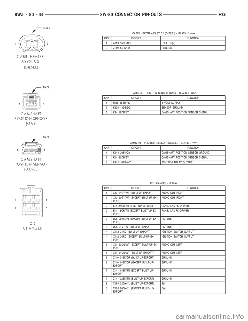
CABIN HEATER ASSIST C2 (DIESEL) - BLACK 2 WAY
CAV CIRCUIT FUNCTION
1 A119 14RD/OR FUSED B(+)
2 Z149 14BK/DB GROUND
CAMSHAFT POSITION SENSOR (GAS) - BLACK 3 WAY
CAV CIRCUIT FUNCTION
1 F888 18BR/PK 8 VOLT SUPPLY
2 K900 18DB/DG SENSOR GROUND
3 K44 18DB/GY CAMSHAFT POSITION SENSOR SIGNAL
CAMSHAFT POSITION SENSOR (DIESEL) - BLACK 3 WAY
CAV CIRCUIT FUNCTION
1 K944 20BK/GY CAMSHAFT POSITION SENSOR GROUND
2 K44 20DB/GY CAMSHAFT POSITION SENSOR SIGNAL
3 K342 16BR/WT ECM/PCM RELAY OUTPUT
CD CHANGER-8WAY
CAV CIRCUIT FUNCTION
1 X40 24GY/WT (BUILT-UP-EXPORT) AUDIO OUT RIGHT
1 X40 20GY/WT (EXCEPT BUILT-UP-EX-
PORT)AUDIO OUT RIGHT
2 E14 24OR/TN (BUILT-UP-EXPORT) PANEL LAMPS DRIVER
2 E14 18OR/TN (EXCEPT BUILT-UP-EX-
PORT)PANEL LAMPS DRIVER
3 D25 20WT/VT (EXCEPT BUILT-UP-EX-
PORT)PCI BUS
3 D25 24VT/YL (BUILT-UP-EXPORT) PCI BUS
4 X112 24RD (BUILT-UP-EXPORT) IGNITION SWITCH OUTPUT
4 X112 20RD (EXCEPT BUILT-UP-EX-
PORT)IGNITION SWITCH OUTPUT
5 X41 20DG/WT (EXCEPT BUILT-UP-EX-
PORT)AUDIO OUT LEFT
5 X41 24DG/WT (BUILT-UP-EXPORT) AUDIO OUT LEFT
6 Z140 24BK/OR (BUILT-UP-EXPORT) GROUND
6 Z140 18BK/OR (EXCEPT BUILT-UP-
EXPORT)GROUND
7 Z141 18BK/TN (EXCEPT BUILT-UP-
EXPORT)GROUND
7 Z141 22BK/TN (BUILT-UP-EXPORT) GROUND
8 X160 22GY/YL (BUILT-UP-EXPORT) B(+)
8 X160 20GY/YL (EXCEPT BUILT-UP-
EXPORT)B(+)
8Wa - 80 - 44 8W-80 CONNECTOR PIN-OUTSRG
Page 2565 of 4284
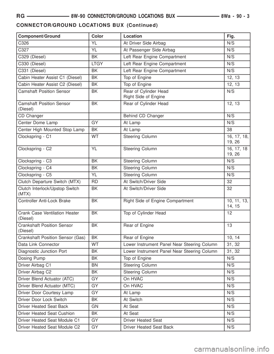
Component/Ground Color Location Fig.
C326 YL At Driver Side Airbag N/S
C327 YL At Passenger Side Airbag N/S
C329 (Diesel) BK Left Rear Engine Compartment N/S
C330 (Diesel) LTGY Left Rear Engine Compartment N/S
C331 (Diesel) BK Left Rear Engine Compartment N/S
Cabin Heater Assist C1 (Diesel) BK Top of Engine 12, 13
Cabin Heater Assist C2 (Diesel) BK Top of Engine 12, 13
Camshaft Position Sensor BK Rear of Cylinder Head
Right Side of EngineN/S
Camshaft Position Sensor
(Diesel)BK Rear of Cylinder Head 12, 13
CD Changer Behind CD Changer N/S
Center Dome Lamp GY At Lamp N/S
Center High Mounted Stop Lamp BK At Lamp 38
Clockspring - C1 WT Steering Column 16, 17, 18,
19, 26
Clockspring - C2 YL Steering Column 16, 17, 18
19, 26
Clockspring - C3 BK Steering Column N/S
Clockspring - C4 BK Steering Column N/S
Clockspring - C5 YL Steering Column N/S
Clutch Departure Switch (MTX) RD At Switch/Driver Side 32
Clutch Interlock/Upstop Switch
(MTX)BK At Switch/Driver Side 32
Controller Anti-Lock Brake BK Right Side of Engine Compartment 10, 11, 13,
14, 15
Crank Case Ventilation Heater
(Diesel)BK Top of Cylinder Head 12
Crankshaft Position Sensor
(Diesel)BK Rear of Engine 13
Crankshaft Position Sensor (Gas) BK Rear of Engine 10, 14
Data Link Connector WT Lower Instrument Panel Near Steering Column 31, 32
Diagnostic Junction Port BK Lower Instrument Panel Near Steering Column 31, 32
Dosing Pump BK Top of Engine N/S
Driver Airbag C1 BN Steering Column N/S
Driver Airbag C2 BK Steering Column N/S
Driver Blend Actuator (ATC) GY On HVAC N/S
Driver Blend Actuator (MTC) GY On HVAC N/S
Driver Door Courtesy Lamp GY At Lamp N/S
Driver Door Lock Switch BK At Switch N/S
Driver Heated Seat Back GN At Seat N/S
Driver Heated Seat Cushion BK At Seat N/S
Driver Heated Seat Module C1 GY Driver Heated Seat N/S
Driver Heated Seat Module C2 GY Driver Heated Seat Back N/S
RG8W-90 CONNECTOR/GROUND LOCATIONS BUX8Wa-90-3
CONNECTOR/GROUND LOCATIONS BUX (Continued)
Page 2986 of 4284
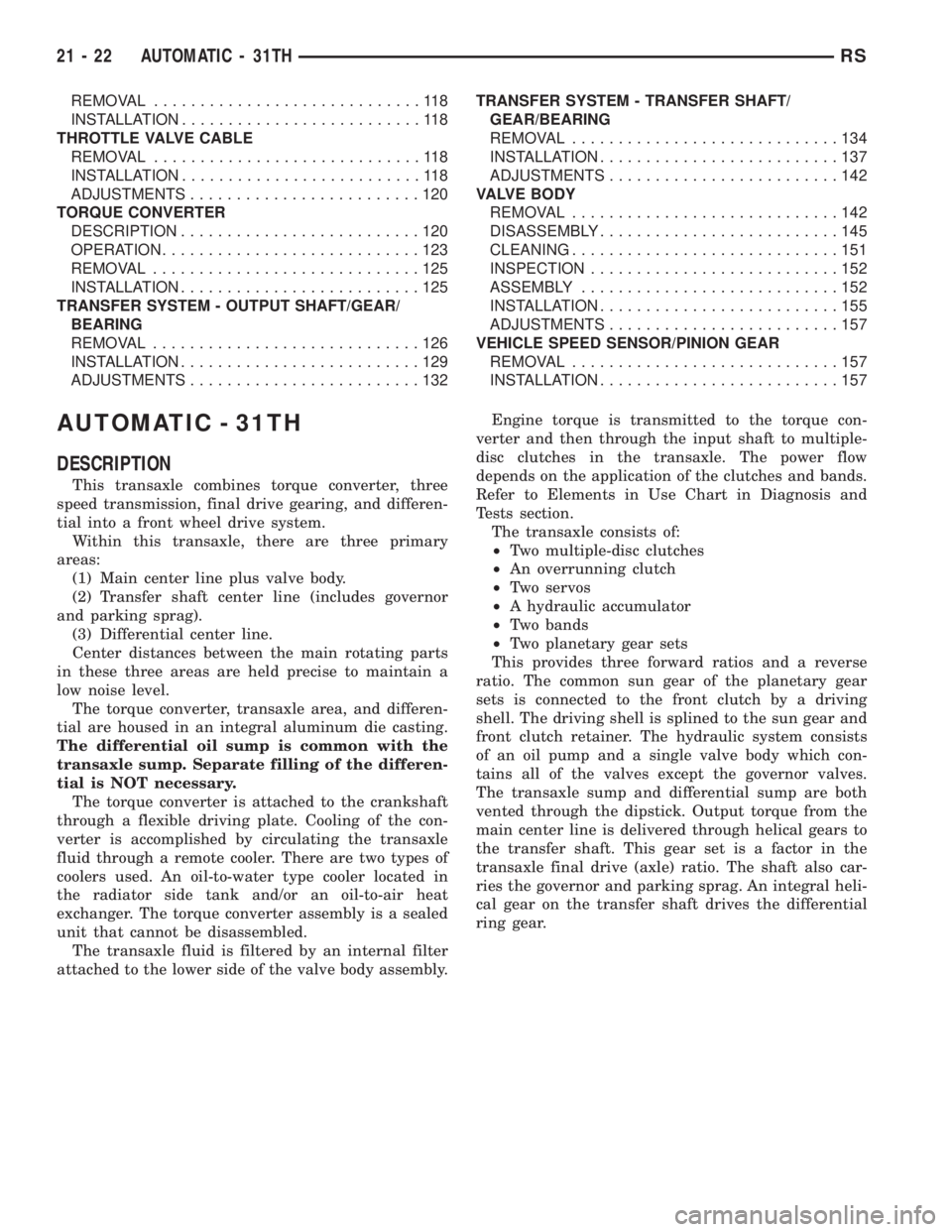
REMOVAL.............................118
INSTALLATION..........................118
THROTTLE VALVE CABLE
REMOVAL.............................118
INSTALLATION..........................118
ADJUSTMENTS.........................120
TORQUE CONVERTER
DESCRIPTION..........................120
OPERATION............................123
REMOVAL.............................125
INSTALLATION..........................125
TRANSFER SYSTEM - OUTPUT SHAFT/GEAR/
BEARING
REMOVAL.............................126
INSTALLATION..........................129
ADJUSTMENTS.........................132TRANSFER SYSTEM - TRANSFER SHAFT/
GEAR/BEARING
REMOVAL.............................134
INSTALLATION..........................137
ADJUSTMENTS.........................142
VALVE BODY
REMOVAL.............................142
DISASSEMBLY..........................145
CLEANING.............................151
INSPECTION...........................152
ASSEMBLY............................152
INSTALLATION..........................155
ADJUSTMENTS.........................157
VEHICLE SPEED SENSOR/PINION GEAR
REMOVAL.............................157
INSTALLATION..........................157
AUTOMATIC - 31TH
DESCRIPTION
This transaxle combines torque converter, three
speed transmission, final drive gearing, and differen-
tial into a front wheel drive system.
Within this transaxle, there are three primary
areas:
(1) Main center line plus valve body.
(2) Transfer shaft center line (includes governor
and parking sprag).
(3) Differential center line.
Center distances between the main rotating parts
in these three areas are held precise to maintain a
low noise level.
The torque converter, transaxle area, and differen-
tial are housed in an integral aluminum die casting.
The differential oil sump is common with the
transaxle sump. Separate filling of the differen-
tial is NOT necessary.
The torque converter is attached to the crankshaft
through a flexible driving plate. Cooling of the con-
verter is accomplished by circulating the transaxle
fluid through a remote cooler. There are two types of
coolers used. An oil-to-water type cooler located in
the radiator side tank and/or an oil-to-air heat
exchanger. The torque converter assembly is a sealed
unit that cannot be disassembled.
The transaxle fluid is filtered by an internal filter
attached to the lower side of the valve body assembly.Engine torque is transmitted to the torque con-
verter and then through the input shaft to multiple-
disc clutches in the transaxle. The power flow
depends on the application of the clutches and bands.
Refer to Elements in Use Chart in Diagnosis and
Tests section.
The transaxle consists of:
²Two multiple-disc clutches
²An overrunning clutch
²Two servos
²A hydraulic accumulator
²Two bands
²Two planetary gear sets
This provides three forward ratios and a reverse
ratio. The common sun gear of the planetary gear
sets is connected to the front clutch by a driving
shell. The driving shell is splined to the sun gear and
front clutch retainer. The hydraulic system consists
of an oil pump and a single valve body which con-
tains all of the valves except the governor valves.
The transaxle sump and differential sump are both
vented through the dipstick. Output torque from the
main center line is delivered through helical gears to
the transfer shaft. This gear set is a factor in the
transaxle final drive (axle) ratio. The shaft also car-
ries the governor and parking sprag. An integral heli-
cal gear on the transfer shaft drives the differential
ring gear.
21 - 22 AUTOMATIC - 31THRS
Page 3035 of 4284
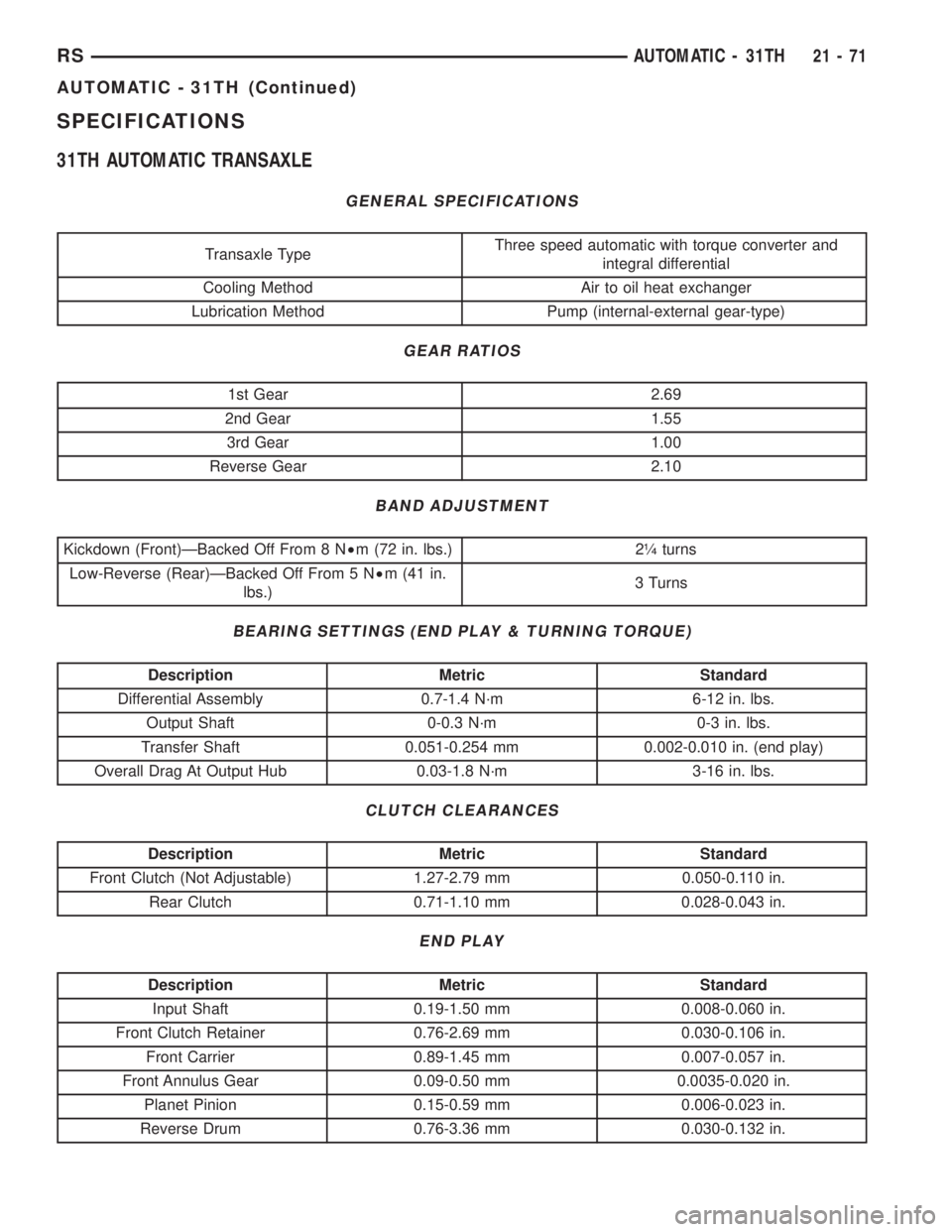
SPECIFICATIONS
31TH AUTOMATIC TRANSAXLE
GENERAL SPECIFICATIONS
Transaxle TypeThree speed automatic with torque converter and
integral differential
Cooling Method Air to oil heat exchanger
Lubrication Method Pump (internal-external gear-type)
GEAR RATIOS
1st Gear 2.69
2nd Gear 1.55
3rd Gear 1.00
Reverse Gear 2.10
BAND ADJUSTMENT
Kickdown (Front)ÐBacked Off From 8 N²m (72 in. lbs.) 2ò turns
Low-Reverse (Rear)ÐBacked Off From 5 N²m (41 in.
lbs.)3 Turns
BEARING SETTINGS (END PLAY & TURNING TORQUE)
Description Metric Standard
Differential Assembly 0.7-1.4 N´m 6-12 in. lbs.
Output Shaft 0-0.3 N´m 0-3 in. lbs.
Transfer Shaft 0.051-0.254 mm 0.002-0.010 in. (end play)
Overall Drag At Output Hub 0.03-1.8 N´m 3-16 in. lbs.
CLUTCH CLEARANCES
Description Metric Standard
Front Clutch (Not Adjustable) 1.27-2.79 mm 0.050-0.110 in.
Rear Clutch 0.71-1.10 mm 0.028-0.043 in.
END PLAY
Description Metric Standard
Input Shaft 0.19-1.50 mm 0.008-0.060 in.
Front Clutch Retainer 0.76-2.69 mm 0.030-0.106 in.
Front Carrier 0.89-1.45 mm 0.007-0.057 in.
Front Annulus Gear 0.09-0.50 mm 0.0035-0.020 in.
Planet Pinion 0.15-0.59 mm 0.006-0.023 in.
Reverse Drum 0.76-3.36 mm 0.030-0.132 in.
RSAUTOMATIC - 31TH21-71
AUTOMATIC - 31TH (Continued)