rear view mirror CHRYSLER VOYAGER 2001 Owner's Manual
[x] Cancel search | Manufacturer: CHRYSLER, Model Year: 2001, Model line: VOYAGER, Model: CHRYSLER VOYAGER 2001Pages: 4284, PDF Size: 83.53 MB
Page 3623 of 4284
STATIONARY GLASS
TABLE OF CONTENTS
page page
WINDSHIELD
DESCRIPTION..........................243
WARNING.............................243
REMOVAL.............................243
INSTALLATION..........................244
SLIDING DOOR GLASS
REMOVAL.............................245INSTALLATION..........................245
QUARTER WINDOW
REMOVAL.............................246
INSTALLATION..........................246
REAR DOOR GLASS
REMOVAL.............................246
INSTALLATION..........................246
WINDSHIELD
DESCRIPTION
The windshield is attached to the window frame
with urethane adhesive. The urethane adhesive is
applied cold and seals the surface area between the
window opening and the glass. The primer adheres
the urethane adhesive to the windshield.
It is difficult to salvage a windshield during the
removal operation. The windshield is part of the
structural support for the roof. The urethane bonding
used to secure the windshield to the fence is difficult
to cut or clean from any surface. If the moldings are
set in urethane, it would also be unlikely they could
be salvaged. Before removing the windshield, check
the availability of the windshield and moldings from
the parts supplier.
WINDSHIELD SAFETY PRECAUTIONS
WARNING: DO NOT OPERATE THE VEHICLE
WITHIN 24 HOURS OF WINDSHIELD INSTALLATION.
IT TAKES AT LEAST 24 HOURS FOR URETHANE
ADHESIVE TO CURE. IF IT IS NOT CURED, THE
WINDSHIELD MAY NOT PERFORM PROPERLY IN
AN ACCIDENT.
URETHANE ADHESIVES ARE APPLIED AS A SYS-
TEM. USE GLASS CLEANER, GLASS PREP SOL-
VENT, GLASS PRIMER, PVC (VINYL) PRIMER AND
PINCH WELD (FENCE) PRIMER PROVIDED BY THE
ADHESIVE MANUFACTURER. IF NOT, STRUCTURAL
INTEGRITY COULD BE COMPROMISED.
DAIMLERCHRYSLER DOES NOT RECOMMEND
GLASS ADHESIVE BY BRAND. TECHNICIANS
SHOULD REVIEW PRODUCT LABELS AND TECHNI-
CAL DATA SHEETS, AND USE ONLY ADHESIVES
THAT THEIR MANUFACTURES WARRANT WILL
RESTORE A VEHICLE TO THE REQUIREMENTS OF
FMVSS 212. TECHNICIANS SHOULD ALSO INSURE
THAT PRIMERS AND CLEANERS ARE COMPATIBLEWITH THE PARTICULAR ADHESIVE USED.
BE SURE TO REFER TO THE URETHANE MANU-
FACTURER'S DIRECTIONS FOR CURING TIME
SPECIFICATIONS, AND DO NOT USE ADHESIVE
AFTER ITS EXPIRATION DATE.
VAPORS THAT ARE EMITTED FROM THE URE-
THANE ADHESIVE OR PRIMER COULD CAUSE
PERSONAL INJURY. USE THEM IN A WELL-VENTI-
LATED AREA.
SKIN CONTACT WITH URETHANE ADHESIVE
SHOULD BE AVOIDED. PERSONAL INJURY MAY
RESULT.
ALWAYS WEAR EYE AND HAND PROTECTION
WHEN WORKING WITH GLASS.
CAUTION: Protect all painted and trimmed surfaces
from coming in contact with urethane or primers.
Be careful not to damage painted surfaces when
removing moldings or cutting urethane around
windshield.
REMOVAL
WINDSHIELD REMOVAL ± EXTERIOR METHOD
The urethane adhesive holding the windshield to
the opening pinch weld (fence) can be cut using a
sharp cold knife from the exterior of the vehicle.
Using the cold knife method is effective if the wind-
shield is already broken. If the glass must be sal-
vaged, cutting the urethane adhesive from the
interior of the vehicle using a reciprocating or oscil-
lating power knife is recommended.
(1) Remove inside rear view mirror.
(2) Remove windshield wiper arms.
(3) Remove cowl cover.
(4) Remove A-pillar trim panels.
(5) Disconnect wire connectors to windshield
defroster grid.
RSSTATIONARY GLASS23 - 243
Page 3624 of 4284
(6) Place protective covers over instrument panel
and hood.
(7) Remove windshield molding. Using pliers, pull
outward on molding at the bottom of A-pillars.
(8) Using a sharp cold knife, cut urethane adhe-
sive holding the windshield to the A-pillars, roof
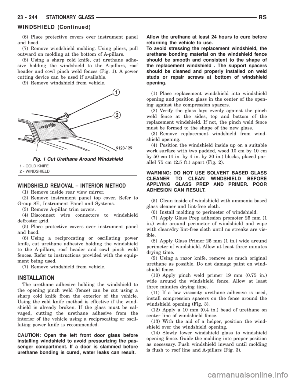
header and cowl pinch weld fences (Fig. 1). A power
cutting device can be used if available.
(9) Remove windshield from vehicle.
WINDSHIELD REMOVAL ± INTERIOR METHOD
(1) Remove inside rear view mirror.
(2) Remove instrument panel top cover. Refer to
Group 8E, Instrument Panel and Systems.
(3) Remove A-pillar trim covers.
(4) Disconnect wire connectors to windshield
defroster grid.
(5) Place protective covers over instrument panel
and hood.
(6) Using a reciprocating or oscillating power
knife, cut urethane adhesive holding the windshield
to the A-pillars, roof header and cowl pinch weld
fences. Refer to instructions provided with the equip-
ment being used.
(7) Remove windshield from vehicle.
INSTALLATION
The urethane adhesive holding the windshield to
the opening pinch weld (fence) can be cut using a
sharp cold knife from the exterior of the vehicle.
Using the cold knife method is effective if the wind-
shield is already broken. If the glass must be sal-
vaged, cutting the urethane adhesive from the
interior of the vehicle using a reciprocating or oscil-
lating power knife is recommended.
CAUTION: Open the left front door glass before
installing windshield to avoid pressurizing the pas-
senger compartment. If a door is slammed before
urethane bonding is cured, water leaks can result.Allow the urethane at least 24 hours to cure before
returning the vehicle to use.
To avoid stressing the replacement windshield, the
urethane bonding material on the windshield fence
should be smooth and consistent to the shape of
the replacement windshield . The support spacers
should be cleaned and properly installed on weld
studs or repair screws at bottom of windshield
opening.
(1) Place replacement windshield into windshield
opening and position glass in the center of the open-
ing against the compression spacers.
(2) Verify the glass lays evenly against the pinch
weld fence at the sides, top and bottom of the
replacement windshield. If not, the pinch weld fence
must be formed to the shape of the new glass.
(3) Remove replacement windshield from wind-
shield opening.
(4) Position the windshield inside up on a suitable
work surface with two padded, wood 10 cm by 10 cm
by 50 cm (4 in. by 4 in. by 20 in.) blocks, placed par-
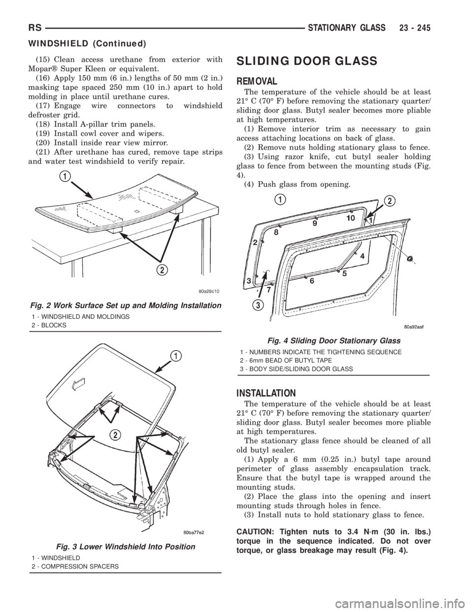
allel 75 cm (2.5 ft.) apart (Fig. 2).
WARNING: DO NOT USE SOLVENT BASED GLASS
CLEANER TO CLEAN WINDSHIELD BEFORE
APPLYING GLASS PREP AND PRIMER. POOR
ADHESION CAN RESULT.
(5) Clean inside of windshield with ammonia based
glass cleaner and lint-free cloth.
(6) Install molding to perimeter of windshield.
(7) Apply Glass Prep adhesion promoter 25 mm (1
in.) wide around perimeter of windshield and wipe
with clean/dry lint-free cloth until no streaks are vis-
ible.
(8) Apply Glass Primer 25 mm (1 in.) wide around
perimeter of windshield. Allow at least three minutes
drying time.
(9) Using a razor knife, remove as much original
urethane as possible. Do not damage paint on wind-
shield fence.
(10) Apply pinch weld primer 19 mm (0.75 in.)
wide around the windshield fence. Allow at least
three minutes drying time.
(11) If a low viscosity urethane adhesive is used,
install compression spacers on the fence around the
windshield opening (Fig. 3).
(12) Apply a 10 mm (0.4 in.) bead of urethane on
center line of windshield fence.
(13) With the aid of a helper, position the wind-
shield over the windshield opening.
(14) Slowly lower windshield glass to windshield
opening fence. Guide the molding into proper position
as necessary. Push windshield inward until molding
is flush to roof line and A-pillars (Fig. 3).
Fig. 1 Cut Urethane Around Windshield
1 - COLD KNIFE
2 - WINDSHIELD
23 - 244 STATIONARY GLASSRS
WINDSHIELD (Continued)
Page 3625 of 4284
(15) Clean access urethane from exterior with
Moparž Super Kleen or equivalent.
(16) Apply 150 mm (6 in.) lengths of 50 mm (2 in.)
masking tape spaced 250 mm (10 in.) apart to hold
molding in place until urethane cures.
(17) Engage wire connectors to windshield
defroster grid.
(18) Install A-pillar trim panels.
(19) Install cowl cover and wipers.
(20) Install inside rear view mirror.
(21) After urethane has cured, remove tape strips
and water test windshield to verify repair.SLIDING DOOR GLASS
REMOVAL
The temperature of the vehicle should be at least
21É C (70É F) before removing the stationary quarter/
sliding door glass. Butyl sealer becomes more pliable
at high temperatures.
(1) Remove interior trim as necessary to gain
access attaching locations on back of glass.
(2) Remove nuts holding stationary glass to fence.
(3) Using razor knife, cut butyl sealer holding
glass to fence from between the mounting studs (Fig.
4).
(4) Push glass from opening.
INSTALLATION
The temperature of the vehicle should be at least
21É C (70É F) before removing the stationary quarter/
sliding door glass. Butyl sealer becomes more pliable
at high temperatures.
The stationary glass fence should be cleaned of all
old butyl sealer.
(1) Applya6mm(0.25 in.) butyl tape around
perimeter of glass assembly encapsulation track.
Ensure that the butyl tape is wrapped around the
mounting studs.
(2) Place the glass into the opening and insert
mounting studs through holes in fence.
(3) Install nuts to hold stationary glass to fence.
CAUTION: Tighten nuts to 3.4 N´m (30 in. lbs.)
torque in the sequence indicated. Do not over
torque, or glass breakage may result (Fig. 4).
Fig. 2 Work Surface Set up and Molding Installation
1 - WINDSHIELD AND MOLDINGS
2 - BLOCKS
Fig. 3 Lower Windshield Into Position
1 - WINDSHIELD
2 - COMPRESSION SPACERS
Fig. 4 Sliding Door Stationary Glass
1 - NUMBERS INDICATE THE TIGHTENING SEQUENCE
2 - 6mm BEAD OF BUTYL TAPE
3 - BODY SIDE/SLIDING DOOR GLASS
RSSTATIONARY GLASS23 - 245
WINDSHIELD (Continued)
Page 3634 of 4284
cloudy days and at night it will probably be slightly
warmer. Infrared Three-Zone Temperature Control
provides side-to-side and front-to-rear variation in
comfort temperature settings. The Infrared Three-
Zone Automatic Temperature Control fan provides a
continuously variable air flow rate to meet occupant
comfort requirements.
FRONT CONTROL PANEL
²AUTO HI/LO± This system features two sets of
automatic control logic that allow either a rapid cool-
down rate or a somewhat slower cool-down rate with
less fan noise. HI-AUTO controls the system to reach
its assigned temperature quickly with a higher fan
speed. LO-AUTO controls the system to reach its
assigned temperature somewhat slower with less fan
noise. Both modes will automatically engage auto
recirculation.
²DE-FROST± The front de-frost function is
active when the rear window defogger function is
active or when the defog/defrost mode is selected.
²RECIRC± The RECIRC button will close the
air inlet door. If the system is in auto recirc (indica-
tor being displayed automatically), pressing the man-
ual recirc button will disable the auto recirc function
until one of the auto keys are pressed or the ignition
is cycled. If Auto HI/LO is pressed while manual
recirc is active, manual recirc will be deactivated.
²REAR WINDOW DEFOGGER± Pushing the
button sends a PCI bus message to the Intelligent
Power Module which controls the Rear Window
Defogger and side view mirror (if equipped) circuitry.
The defogger function will be active for 10 minutes
and can be turned off by a switch press. The defogger
will function while the control is in the OFF mode.
²FAN/MODE± The Fan and Mode knobs have
17 manual selectable positions. Manually changing
either of the rotary knobs for mode or fan speed set-
tings makes control of that function alone manual for
as long as the ignition is on. If only one is changed
manually, the other remains under automatic control.
Pressing the HI-AUTO/LO-AUTO rocker switch
restores full automatic control.
²REAR CONTROL± When the Rear System
control knob is moved to the OFF position, there will
be a delay of approximately 1 second before the sys-
tem actually turns off. This delay is to prevent an
undesired blower dropout if the knob is moved
through OFF to the other selections.
²BLOWER DELAY TIMER± The word DELAY
is displayed at start-up to signify that the system is
waiting so that cold air will not be blowing. This tells
the operator that it is unnecessary to turn the sys-
tem off, raise the temperature setting or turn the fan
speed setting down to prevent cold air from blowing.
A countdown in minutes and seconds until the engineis warm enough to begin delivering heat to the pas-
sengers alternates with the DELAY message at 25
second intervals. This countdown is based on actual
measurement of the rate of engine coolant tempera-
ture change. During the delay time, Defrost mode is
selected and the fan operates at a low speed to keep
the windshield fog free.
REAR CONTROL PANEL
Primary control of the rear compartment unit is in
the instrument panel center stack. The rear unit con-
trol knob there allows the driver to turn the rear
unit off, allow control by the intermediate seat occu-
pants by switching to the REAR position, or provide
fully automatic control based on the temperature set-
ting shown on the front control display.
²REAR CONTROL± Selecting automatic control
of the rear unit at the instrument panel, illuminates
a Locked Padlock in the rear control panel display.
Selecting REAR activates the rear control panel and
the Padlock then appears unlocked.
²FAN KNOB± The rear fan control has Off and
AUTO positions and a range of manual speed set-
tings that override the AUTO setting.
²MODE KNOB± The mode control allows inter-
mediate seat occupants to manually override the
automatic mode and select any balance of air flow
between overhead and floor outlets from full over-
head to full floor.
²SET TEMP± The rear set temp control will
operate identical to the front controls. If the front
control rear set temp button is pressed simulta-
neously with the rear control head, then the front
control head press events shall have priority, i.e. if
the front user presses Rear Set Temp down and the
rear user presses Set Temp up, then the rear set
temp will decrease.
DIAGNOSIS AND TESTING - A/C COOL DOWN
TEST
The heater-A/C control module can perform an A/C
cool down test, which is a test performed during the
manufacturing process to confirm that the air condi-
tioning system is performing satisfactorily. This test
can also provide a quick confirmation of air condi-
tioning system performance to the service technician.
If the test is completed satisfactorily, no further ser-
vice is required. If the test is failed, proceed to the
A/C Performance Test to confirm the a/c system is
operating properly, or use a DRBIIItscan tool to
diagnose the A/C system control and distribution sys-
tems. Refer to the appropriate diagnostic informa-
tion.
24 - 4 HEATING & AIR CONDITIONINGRS
HEATING & AIR CONDITIONING (Continued)
Page 3805 of 4284
important to block the wheels on front-wheel drive
vehicles; the parking brake does not hold the drive
wheels.
When servicing a vehicle, always wear eye pro-
tection, and remove any metal jewelry such as
watchbands or bracelets that might make an inad-
vertent electrical contact.
When diagnosing a powertrain system problem,
it is important to follow approved procedures where
applicable. These procedures can be found in ser-
vice manual procedures. Following these proce-
dures is very important to the safety of individuals
performing diagnostic tests.
4.2.2 VEHICLE PREPARATION FOR
TESTING
Make sure the vehicle being tested has a fully
charged battery. If it does not, false diagnostic codes
or error messages may occur.
4.2.3 SERVICING SUB ASSEMBLIES
Some components of the powertrain system are
intended to be serviced in assembly only. Attempt-
ing to remove or repair certain system sub-
components may result in personal injury and/or
improper system operation. Only those components
with approved repair and installation procedures in
the service manual should be serviced.
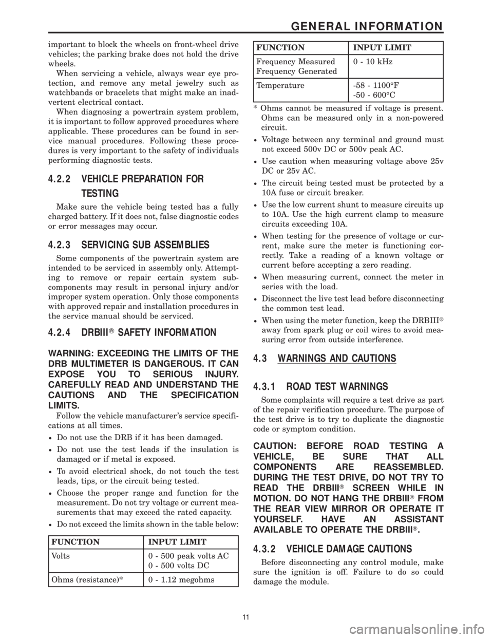
4.2.4 DRBIIITSAFETY INFORMATION
WARNING: EXCEEDING THE LIMITS OF THE
DRB MULTIMETER IS DANGEROUS. IT CAN
EXPOSE YOU TO SERIOUS INJURY.
CAREFULLY READ AND UNDERSTAND THE
CAUTIONS AND THE SPECIFICATION
LIMITS.
Follow the vehicle manufacturer 's service specifi-
cations at all times.
²Do not use the DRB if it has been damaged.
²Do not use the test leads if the insulation is
damaged or if metal is exposed.
²To avoid electrical shock, do not touch the test
leads, tips, or the circuit being tested.
²Choose the proper range and function for the
measurement. Do not try voltage or current mea-
surements that may exceed the rated capacity.
²Do not exceed the limits shown in the table below:
FUNCTION INPUT LIMIT
Volts 0 - 500 peak volts AC
0 - 500 volts DC
Ohms (resistance)* 0 - 1.12 megohms
FUNCTION INPUT LIMIT
Frequency Measured
Frequency Generated0-10kHz
Temperature -58 - 1100ÉF
-50 - 600ÉC
* Ohms cannot be measured if voltage is present.
Ohms can be measured only in a non-powered
circuit.
²Voltage between any terminal and ground must
not exceed 500v DC or 500v peak AC.
²Use caution when measuring voltage above 25v
DC or 25v AC.
²The circuit being tested must be protected by a
10A fuse or circuit breaker.
²Use the low current shunt to measure circuits up
to 10A. Use the high current clamp to measure
circuits exceeding 10A.
²When testing for the presence of voltage or cur-
rent, make sure the meter is functioning cor-
rectly. Take a reading of a known voltage or
current before accepting a zero reading.
²When measuring current, connect the meter in
series with the load.
²Disconnect the live test lead before disconnecting
the common test lead.
²When using the meter function, keep the DRBIIIt
away from spark plug or coil wires to avoid mea-
suring error from outside interference.
4.3 WARNINGS AND CAUTIONS
4.3.1 ROAD TEST WARNINGS
Some complaints will require a test drive as part
of the repair verification procedure. The purpose of
the test drive is to try to duplicate the diagnostic
code or symptom condition.
CAUTION: BEFORE ROAD TESTING A
VEHICLE, BE SURE THAT ALL
COMPONENTS ARE REASSEMBLED.
DURING THE TEST DRIVE, DO NOT TRY TO
READ THE DRBIIITSCREEN WHILE IN
MOTION. DO NOT HANG THE DRBIIITFROM
THE REAR VIEW MIRROR OR OPERATE IT
YOURSELF. HAVE AN ASSISTANT
AVAILABLE TO OPERATE THE DRBIIIT.
4.3.2 VEHICLE DAMAGE CAUTIONS
Before disconnecting any control module, make
sure the ignition is off. Failure to do so could
damage the module.
11
GENERAL INFORMATION
Page 4124 of 4284
4.3 WARNINGS
4.3.1 VEHICLE DAMAGE WARNINGS
Before disconnecting any control module, make
sure the ignition is ªoffº. Failure to do so could
damage the module.
When testing voltage or continuity at any control
module, use the terminal side (not the wire end) of
the connector. Do not probe a wire through the
insulation; this will damage it and eventually cause
it to fail because of corrosion.
Be careful when performing electrical tests so as
to prevent accidental shorting of terminals. Such
mistakes can damage fuses or components. Also, a
second code could be set, making diagnosis of the
original problem more difficult.
4.3.2 ROAD TEST COMPLAINT VEHICLE
Some complaints will require a test drive as part
of the repair verification procedure. The purpose of
the test drive is to try to duplicate the diagnostic
code or symptom condition.
CAUTION: BEFORE ROAD TESTING A
VEHICLE, BE SURE THAT ALL
COMPONENTS ARE REASSEMBLED.
DURING THE TEST DRIVE, DO NOT TRY TO
READ THE DRBIIITSCREEN WHILE IN
MOTION. DO NOT HANG THE DRBIIITFROM
THE REAR VIEW MIRROR OR OPERATE IT
YOURSELF. HAVE AN ASSISTANT
AVAILABLE TO OPERATE THE DRBIIIT.
Road testing is an essential step in the diagnostic
process that must not be overlooked. Along with
diagnostic information obtained from the DRBIIIt
Scan Tool and the original customer concern, the
road test helps to verify the problem and observe
operation under actual vehicle driving conditions.
Just as important as the road test is, there are
preliminary inspections that should be carried out
prior to the road test. Always check the fluid level
and condition before going on a road test or per-
forming other tests. Also try to determine the type
of fluid being used. Improper fluid can result in
problems. Additionally, a variety of complaints can
be caused by incorrect fluid level. Some of the
conditions caused by incorrect fluid level are as
follows:
²Delayed engagement
²Poor shifting or erratic shifts
²Excessive noise
²Overheating
The next step is to verify that the shift linkage is
correctly adjusted. If the gearshift linkage is incor-rectly adjusted because of wear or incorrect adjust-
ment, a number of complaints can result.
The TCM monitors the Shift Lever Position (SLP)
Sensor at all times. If the linkage is incorrectly
adjusted, the TCM may sense a shift lever position
that is not correct for the gear range chosen by the
driver. This may cause diagnostic trouble codes to
be set and a possible limp-in situation.
The following complaints may also be the result
of an incorrectly adjusted or worn linkage.
²Delayed clutch engagement or erratic shifts
²Vehicle able to drive in Neutral
²Engine not able to crank in Park or Neutral
²Gearshift linkage able to be shifted without the
key in the ignition
²Not able to remove the ignition key in Reverse
²Parking pawl not engaging
The shift linkage should also be adjusted when
replacing the transaxle, repairing the valve body or
repairing any component between the shift lever
and the transaxle.
Some questions to ask yourself when considering
the road test are listed below:
²Is the complaint or concern what you think it is,
based the driver 's description of the problem?
²Is the transaxle operating normally, or is there a
real problem?
²When does the malfunction occur?
²Is the problem in only one gear range?
²What temperature does the complaint occur?
²Is the transaxle in limp-in mode?
4.3.3 ELECTRONIC PINION FACTOR
WARNINGS
The pinion factor must be set for all new trans-
mission control modules. If the pinion factor is not
set or if it is set incorrectly, any speedometer, speed
control, rolling door locks, and other devices that
are operated by the powertrain and body controllers
will not function properly.
4.3.4 BULLETINS AND RECALLS
The service procedures contained in this manual
are correct. provided that all applicable Safety
Recalls and Technical Service Bulletins have been
performed.
5.0 REQUIRED TOOLS AND
EQUIPMENT
> DRBIIIt(diagnostic read-out box) - Must be at
latest release level.
20
GENERAL INFORMATION