turn signal bulb CHRYSLER VOYAGER 2001 Owner's Manual
[x] Cancel search | Manufacturer: CHRYSLER, Model Year: 2001, Model line: VOYAGER, Model: CHRYSLER VOYAGER 2001Pages: 4284, PDF Size: 83.53 MB
Page 1961 of 4284

LAMPS
TABLE OF CONTENTS
page page
LAMPS/LIGHTING - EXTERIOR
SPECIFICATIONS.........................1
FOG LAMP
REMOVAL...............................1
INSTALLATION............................2
FOG LAMP UNIT
ADJUSTMENTS...........................2
FRONT POSITION LAMP
REMOVAL...............................3
INSTALLATION............................3
HEADLAMP
REMOVAL...............................3
INSTALLATION............................3
HEADLAMP LEVELING MOTOR
DIAGNOSIS AND TESTING..................4
HEADLAMP LEVELING MOTOR.............4
REMOVAL...............................4
INSTALLATION............................4
HEADLAMP LEVELING SWITCH
DESCRIPTION............................4DIAGNOSIS AND TESTING..................4
HEADLAMP LEVELING SWITCH............4
HEADLAMP SWITCH
DIAGNOSIS AND TESTING..................5
HEADLAMP SWITCH.....................5
HEADLAMP UNIT
ADJUSTMENTS...........................6
PARK/TURN SIGNAL LAMP
REMOVAL...............................7
INSTALLATION............................7
REAR FOG LAMP
DESCRIPTION............................7
REPEATER LAMP
REMOVAL...............................7
INSTALLATION............................7
TAIL LAMP
REMOVAL...............................8
INSTALLATION............................8
LAMPS/LIGHTING - EXTERIOR
SPECIFICATIONS
EXTERIOR LAMPS
BULB APPLICATION CHART
LAMP BULB TYPE
HEADLAMP H7
FRONT POSITION W5W
FRONT TURN SIGNAL PY21W
SIDE REPEATER T4W
LICENSE PLATE W5W/168
REAR TAIL AND STOP P21/5W
REAR TURN SIGNAL PY21W
BACK-UP P21W
REAR FOG P21W
CENTER HIGH
MOUNTED STOP LAMPW16W/921
For additional bulb applications refer to the domestic
Lamps section of the service manual.
FOG LAMP
REMOVAL
(1) Disconnect and isolate the battery negative
cable.
(2) Remove access cover from under bumper fascia.
(3) Disengage spring clip from fog lamp (Fig. 1).
Fig. 1 FOG LAMP
1 - SPRING CLIP
2 - FOG LAMP BULB
RGLAMPS8La-1
Page 1963 of 4284

FRONT POSITION LAMP
REMOVAL
(1) Disconnect and isolate the battery negative
cable.
(2) Remove the headlamp unit (Fig. 3).
(3) Remove the plastic cover from the back of the
headlamp unit.
(4) Pull front position lamp socket from headlamp
unit.
(5) Pull bulb straight out of socket.
INSTALLATION
(1) Push bulb into the bulb socket.
(2) Insert bulb socket into headlamp unit.
(3) Install cover to the back of the headlamp unit.
(4) Install the headlamp unit.
(5) Connect the battery negative cable.
HEADLAMP
REMOVAL
(1) Disconnect and isolate the battery negative
cable.
(2) Remove the headlamp unit.
(3) Remove the cover (high beam lamp) or rubber
boot (low beam lamp) to access bulbs (Fig. 4).
(4) Disconnect the wire harness connector.
(5) Disengage spring clip from headlamp.
(6) Pull headlamp bulb from back of headlamp
unit.
INSTALLATION
(1) Insert headlamp bulb into headlamp unit.
(2) Engage spring clip to headlamp.
(3) Connect wire harness connector.
(4) Install the cover (high beam lamp) or rubber
boot (low beam lamp) to headlamp unit.
(5) Install the headlamp unit.
(6) Connect the battery negative cable.
Fig. 3 FRONT POSITION LAMP
1 - TURN SIGNAL LAMP
2 - HIGH BEAM LAMP
3 - FRONT POSITION LAMP
4 - LOW BEAM LAMP
Fig. 4 HEADLAMP UNIT
1 - HIGH BEAM LAMP
2 - HEADLAMP LEVELING MOTOR
3 - LOW BEAM LAMP
4 - TURN LAMP
RGLAMPS8La-3
Page 1967 of 4284

PARK/TURN SIGNAL LAMP
REMOVAL
(1) Disconnect and isolate the battery negative
cable.
(2) Remove the headlamp unit.
(3) Twist bulb socket and remove from headlamp
unit (Fig. 10).(4) Twist bulb and remove from bulb socket.
INSTALLATION
(1) Install bulb to bulb socket.
(2) Install bulb socket to headlamp unit.
(3) Install headlamp unit.
(4) Connect battery negative cable.
REAR FOG LAMP
DESCRIPTION
The rear fog lamps are incorporated into the tail
lamp unit. (Refer to 8 - ELECTRICAL/LAMPS/
LIGHTING - EXTERIOR/TAIL LAMP - REMOVAL)
for service procedures.
REPEATER LAMP
REMOVAL
(1) Disconnect and isolate the battery negative
cable.
(2) Push the side repeater lamp to one side and
release retaining tab.
(3) Pull side repeater lamp out and disengage bulb
socket from lamp.
(4) Depress, then rotate and pull bulb from socket.
INSTALLATION
(1) Install bulb to socket.
(2) Push lamp socket into the side repeater lamp.
(3) Position side repeater lamp to hole in fender.
(4) Push side repeater lamp to one side and seat
retaining tab into fender.
(5) Connect battery negative cable.
Fig. 9 HEADLAMP ADJUSTMENT
1 - HEADLAMP ADJUSTMENT - HORIZONTAL
2 - HEADLAMP ADJUSTMENT - VERTICAL
Fig. 10 PARK/TURN SIGNAL LAMP
1 - LOW BEAM HEADLAMP
2 - PARK/TURN SIGNAL LAMP
RGLAMPS8La-7
HEADLAMP UNIT (Continued)
Page 1968 of 4284

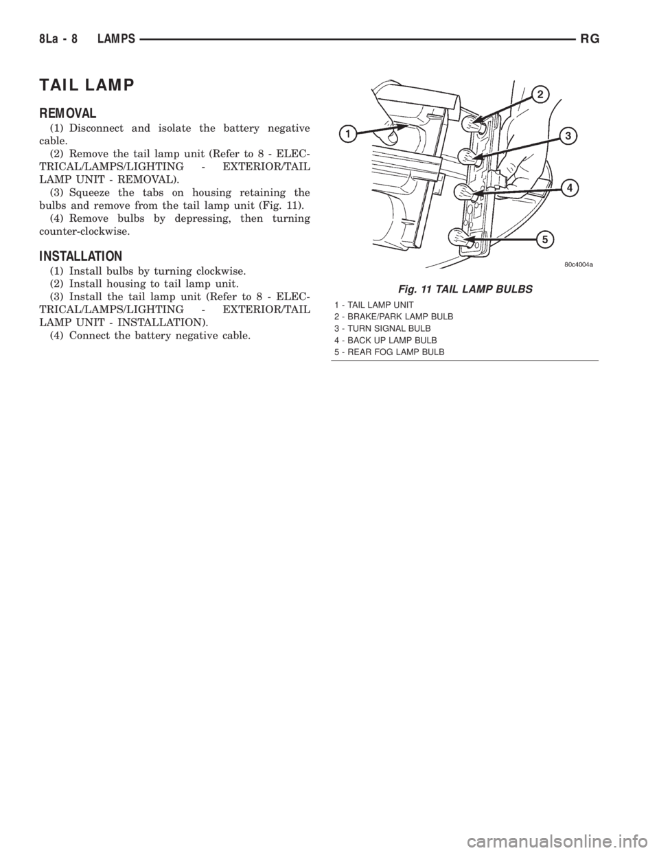
TAIL LAMP
REMOVAL
(1) Disconnect and isolate the battery negative
cable.
(2) Remove the tail lamp unit (Refer to 8 - ELEC-
TRICAL/LAMPS/LIGHTING - EXTERIOR/TAIL
LAMP UNIT - REMOVAL).
(3) Squeeze the tabs on housing retaining the
bulbs and remove from the tail lamp unit (Fig. 11).
(4) Remove bulbs by depressing, then turning
counter-clockwise.
INSTALLATION
(1) Install bulbs by turning clockwise.
(2) Install housing to tail lamp unit.
(3) Install the tail lamp unit (Refer to 8 - ELEC-
TRICAL/LAMPS/LIGHTING - EXTERIOR/TAIL
LAMP UNIT - INSTALLATION).
(4) Connect the battery negative cable.
Fig. 11 TAIL LAMP BULBS
1 - TAIL LAMP UNIT
2 - BRAKE/PARK LAMP BULB
3 - TURN SIGNAL BULB
4 - BACK UP LAMP BULB
5 - REAR FOG LAMP BULB
8La - 8 LAMPSRG