fuse CHRYSLER VOYAGER 2001 Service Manual
[x] Cancel search | Manufacturer: CHRYSLER, Model Year: 2001, Model line: VOYAGER, Model: CHRYSLER VOYAGER 2001Pages: 4284, PDF Size: 83.53 MB
Page 3948 of 4284
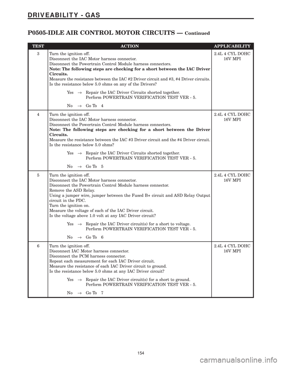
TEST ACTION APPLICABILITY
3 Turn the ignition off.
Disconnect the IAC Motor harness connector.
Disconnect the Powertrain Control Module harness connectors.
Note: The following steps are checking for a short between the IAC Driver
Circuits.
Measure the resistance between the IAC #2 Driver circuit and #3, #4 Driver circuits.
Is the resistance below 5.0 ohms on any of the Drivers?2.4L 4 CYL DOHC
16V MPI
Ye s®Repair the IAC Driver Circuits shorted together.
Perform POWERTRAIN VERIFICATION TEST VER - 5.
No®Go To 4
4 Turn the ignition off.
Disconnect the IAC Motor harness connector.
Disconnect the Powertrain Control Module harness connectors.
Note: The following steps are checking for a short between the Driver
Circuits.
Measure the resistance between the IAC #3 Driver circuit and the #4 Driver circuit.
Is the resistance below 5.0 ohms?2.4L 4 CYL DOHC
16V MPI
Ye s®Repair the IAC Driver Circuits shorted together.
Perform POWERTRAIN VERIFICATION TEST VER - 5.
No®Go To 5
5 Turn the ignition off.
Disconnect the IAC Motor harness connector.
Disconnect the Powertrain Control Module harness connector.
Remove the ASD Relay.
Using a jumper wire, jumper between the Fused B+ circuit and ASD Relay Output
circuit in the PDC.
Turn the ignition on.
Measure the voltage of each of the IAC Driver circuit.
Is the voltage above 1.0 volt at any IAC Driver circuit?2.4L 4 CYL DOHC
16V MPI
Ye s®Repair the IAC Driver circuit(s) for a short to voltage.
Perform POWERTRAIN VERIFICATION TEST VER - 5.
No®Go To 6
6 Turn the ignition off.
Disconnect IAC Motor harness connector.
Disconnect the PCM harness connector.
Repeat each measurement for each IAC Driver circuit.
Measure the resistance of each IAC Driver circuit to ground.
Is the resistance below 5.0 ohms at any IAC Driver circuit?2.4L 4 CYL DOHC
16V MPI
Ye s®Repair the IAC Driver circuit(s) for a short to ground.
Perform POWERTRAIN VERIFICATION TEST VER - 5.
No®Go To 7
154
DRIVEABILITY - GAS
P0505-IDLE AIR CONTROL MOTOR CIRCUITS ÐContinued
Page 3956 of 4284
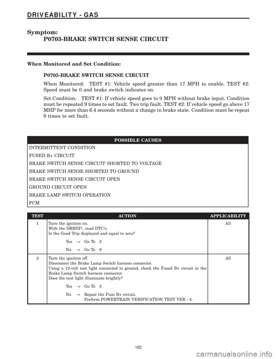
Symptom:
P0703-BRAKE SWITCH SENSE CIRCUIT
When Monitored and Set Condition:
P0703-BRAKE SWITCH SENSE CIRCUIT
When Monitored: TEST #1: Vehicle speed greater than 17 MPH to enable. TEST #2:
Speed must be 0 and brake switch indicates on.
Set Condition: TEST #1: If vehicle speed goes to 0 MPH without brake input. Condition
must be repeated 9 times to set fault. Two trip fault. TEST #2: If vehicle speed go above 17
MHP for more than 6.4 seconds without a change in brake state. Condition must be repeat
9 times to set fault.
POSSIBLE CAUSES
INTERMITTENT CONDITION
FUSED B+ CIRCUIT
BRAKE SWITCH SENSE CIRCUIT SHORTED TO VOLTAGE
BRAKE SWITCH SENSE SHORTED TO GROUND
BRAKE SWITCH SENSE CIRCUIT OPEN
GROUND CIRCUIT OPEN
BRAKE LAMP SWITCH OPERATION
PCM
TEST ACTION APPLICABILITY
1 Turn the ignition on.
With the DRBIIIt, read DTC's.
Is the Good Trip displayed and equal to zero?All
Ye s®Go To 2
No®Go To 9
2 Turn the ignition off.
Disconnect the Brake Lamp Switch harness connector.
Using a 12-volt test light connected to ground, check the Fused B+ circuit in the
Brake Lamp Switch harness connector.
Does the test light illuminate brightly?All
Ye s®Go To 3
No®Repair the Fuse B+ circuit.
Perform POWERTRAIN VERIFICATION TEST VER - 4.
162
DRIVEABILITY - GAS
Page 3957 of 4284
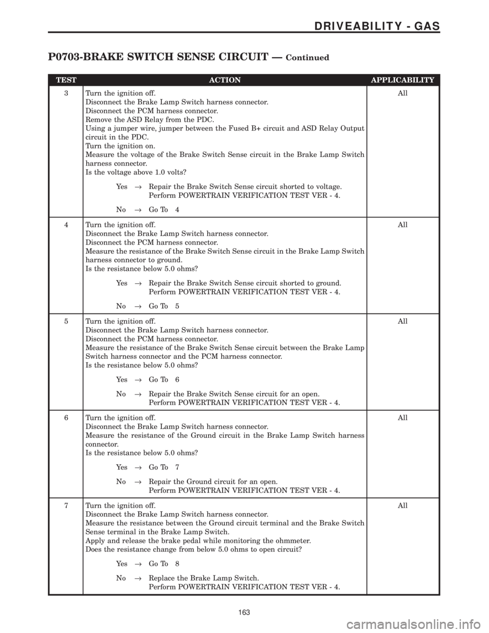
TEST ACTION APPLICABILITY
3 Turn the ignition off.
Disconnect the Brake Lamp Switch harness connector.
Disconnect the PCM harness connector.
Remove the ASD Relay from the PDC.
Using a jumper wire, jumper between the Fused B+ circuit and ASD Relay Output
circuit in the PDC.
Turn the ignition on.
Measure the voltage of the Brake Switch Sense circuit in the Brake Lamp Switch
harness connector.
Is the voltage above 1.0 volts?All
Ye s®Repair the Brake Switch Sense circuit shorted to voltage.
Perform POWERTRAIN VERIFICATION TEST VER - 4.
No®Go To 4
4 Turn the ignition off.
Disconnect the Brake Lamp Switch harness connector.
Disconnect the PCM harness connector.
Measure the resistance of the Brake Switch Sense circuit in the Brake Lamp Switch
harness connector to ground.
Is the resistance below 5.0 ohms?All
Ye s®Repair the Brake Switch Sense circuit shorted to ground.
Perform POWERTRAIN VERIFICATION TEST VER - 4.
No®Go To 5
5 Turn the ignition off.
Disconnect the Brake Lamp Switch harness connector.
Disconnect the PCM harness connector.
Measure the resistance of the Brake Switch Sense circuit between the Brake Lamp
Switch harness connector and the PCM harness connector.
Is the resistance below 5.0 ohms?All
Ye s®Go To 6
No®Repair the Brake Switch Sense circuit for an open.
Perform POWERTRAIN VERIFICATION TEST VER - 4.
6 Turn the ignition off.
Disconnect the Brake Lamp Switch harness connector.
Measure the resistance of the Ground circuit in the Brake Lamp Switch harness
connector.
Is the resistance below 5.0 ohms?All
Ye s®Go To 7
No®Repair the Ground circuit for an open.
Perform POWERTRAIN VERIFICATION TEST VER - 4.
7 Turn the ignition off.
Disconnect the Brake Lamp Switch harness connector.
Measure the resistance between the Ground circuit terminal and the Brake Switch
Sense terminal in the Brake Lamp Switch.
Apply and release the brake pedal while monitoring the ohmmeter.
Does the resistance change from below 5.0 ohms to open circuit?All
Ye s®Go To 8
No®Replace the Brake Lamp Switch.
Perform POWERTRAIN VERIFICATION TEST VER - 4.
163
DRIVEABILITY - GAS
P0703-BRAKE SWITCH SENSE CIRCUIT ÐContinued
Page 3959 of 4284
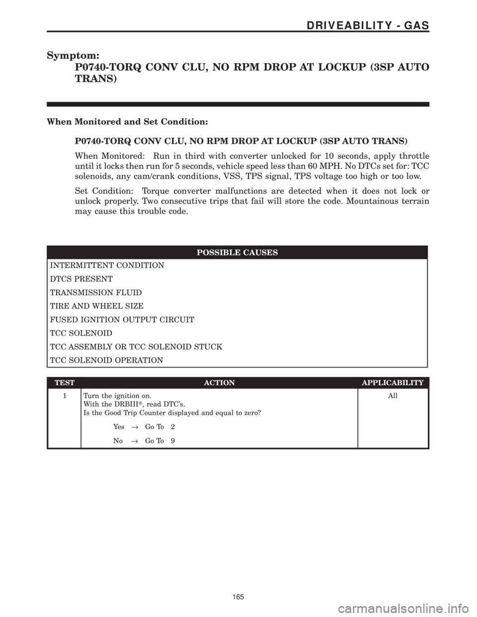
Symptom:
P0740-TORQ CONV CLU, NO RPM DROP AT LOCKUP (3SP AUTO
TRANS)
When Monitored and Set Condition:
P0740-TORQ CONV CLU, NO RPM DROP AT LOCKUP (3SP AUTO TRANS)
When Monitored: Run in third with converter unlocked for 10 seconds, apply throttle
until it locks then run for 5 seconds, vehicle speed less than 60 MPH. No DTCs set for: TCC
solenoids, any cam/crank conditions, VSS, TPS signal, TPS voltage too high or too low.
Set Condition: Torque converter malfunctions are detected when it does not lock or
unlock properly. Two consecutive trips that fail will store the code. Mountainous terrain
may cause this trouble code.
POSSIBLE CAUSES
INTERMITTENT CONDITION
DTCS PRESENT
TRANSMISSION FLUID
TIRE AND WHEEL SIZE
FUSED IGNITION OUTPUT CIRCUIT
TCC SOLENOID
TCC ASSEMBLY OR TCC SOLENOID STUCK
TCC SOLENOID OPERATION
TEST ACTION APPLICABILITY
1 Turn the ignition on.
With the DRBIIIt, read DTC's.
Is the Good Trip Counter displayed and equal to zero?All
Ye s®Go To 2
No®Go To 9
165
DRIVEABILITY - GAS
Page 3960 of 4284
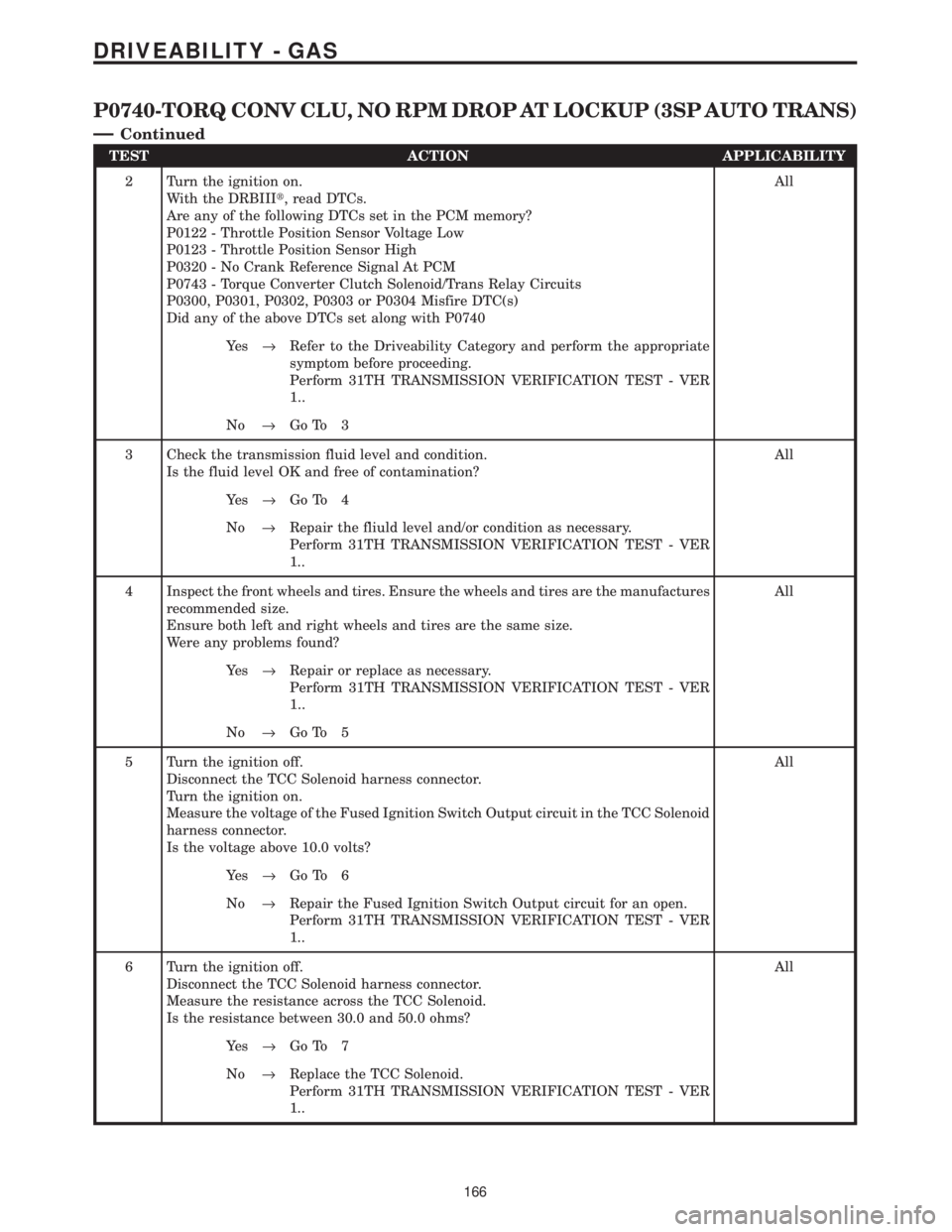
TEST ACTION APPLICABILITY
2 Turn the ignition on.
With the DRBIIIt, read DTCs.
Are any of the following DTCs set in the PCM memory?
P0122 - Throttle Position Sensor Voltage Low
P0123 - Throttle Position Sensor High
P0320 - No Crank Reference Signal At PCM
P0743 - Torque Converter Clutch Solenoid/Trans Relay Circuits
P0300, P0301, P0302, P0303 or P0304 Misfire DTC(s)
Did any of the above DTCs set along with P0740All
Ye s®Refer to the Driveability Category and perform the appropriate
symptom before proceeding.
Perform 31TH TRANSMISSION VERIFICATION TEST - VER
1..
No®Go To 3
3 Check the transmission fluid level and condition.
Is the fluid level OK and free of contamination?All
Ye s®Go To 4
No®Repair the fliuld level and/or condition as necessary.
Perform 31TH TRANSMISSION VERIFICATION TEST - VER
1..
4 Inspect the front wheels and tires. Ensure the wheels and tires are the manufactures
recommended size.
Ensure both left and right wheels and tires are the same size.
Were any problems found?All
Ye s®Repair or replace as necessary.
Perform 31TH TRANSMISSION VERIFICATION TEST - VER
1..
No®Go To 5
5 Turn the ignition off.
Disconnect the TCC Solenoid harness connector.
Turn the ignition on.
Measure the voltage of the Fused Ignition Switch Output circuit in the TCC Solenoid
harness connector.
Is the voltage above 10.0 volts?All
Ye s®Go To 6
No®Repair the Fused Ignition Switch Output circuit for an open.
Perform 31TH TRANSMISSION VERIFICATION TEST - VER
1..
6 Turn the ignition off.
Disconnect the TCC Solenoid harness connector.
Measure the resistance across the TCC Solenoid.
Is the resistance between 30.0 and 50.0 ohms?All
Ye s®Go To 7
No®Replace the TCC Solenoid.
Perform 31TH TRANSMISSION VERIFICATION TEST - VER
1..
166
DRIVEABILITY - GAS
P0740-TORQ CONV CLU, NO RPM DROP AT LOCKUP (3SP AUTO TRANS)
Ð
Continued
Page 3962 of 4284
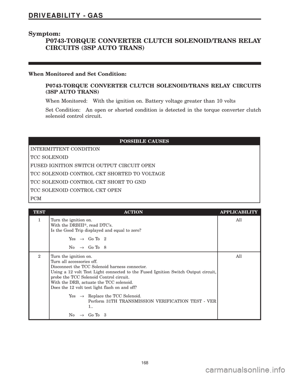
Symptom:
P0743-TORQUE CONVERTER CLUTCH SOLENOID/TRANS RELAY
CIRCUITS (3SP AUTO TRANS)
When Monitored and Set Condition:
P0743-TORQUE CONVERTER CLUTCH SOLENOID/TRANS RELAY CIRCUITS
(3SP AUTO TRANS)
When Monitored: With the ignition on. Battery voltage greater than 10 volts
Set Condition: An open or shorted condition is detected in the torque converter clutch
solenoid control circuit.
POSSIBLE CAUSES
INTERMITTENT CONDITION
TCC SOLENOID
FUSED IGNITION SWITCH OUTPUT CIRCUIT OPEN
TCC SOLENOID CONTROL CKT SHORTED TO VOLTAGE
TCC SOLENOID CONTROL CKT SHORT TO GND
TCC SOLENOID CONTROL CKT OPEN
PCM
TEST ACTION APPLICABILITY
1 Turn the ignition on.
With the DRBIIIt, read DTC's.
Is the Good Trip displayed and equal to zero?All
Ye s®Go To 2
No®Go To 8
2 Turn the ignition on.
Turn all accessories off.
Disconnect the TCC Solenoid harness connector.
Using a 12 volt Test Light connected to the Fused Ignition Switch Output circuit,
probe the TCC Solenoid Control circuit.
With the DRB, actuate the TCC solenoid.
Does the 12 volt test light flash on and off?All
Ye s®Replace the TCC Solenoid.
Perform 31TH TRANSMISSION VERIFICATION TEST - VER
1..
No®Go To 3
168
DRIVEABILITY - GAS
Page 3963 of 4284
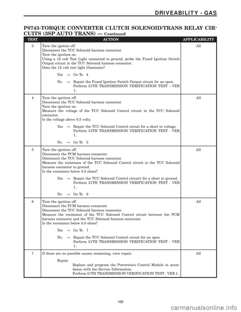
TEST ACTION APPLICABILITY
3 Turn the igntion off.
Disconnect the TCC Solenoid harness connector.
Turn the ignition on.
Using a 12 volt Test Light connected to ground, probe the Fused Ignition Switch
Output circuit in the TCC Solenoid harness connector.
Does the 12 volt test light illuminate?All
Ye s®Go To 4
No®Repair the Fused Ignition Switch Output circuit for an open.
Perform 31TH TRANSMISSION VERIFICATION TEST - VER
1..
4 Turn the ignition off.
Disconnect the TCC Solenoid harness connector.
Turn the ignition on.
Measure the voltage of the TCC Solenoid Control circuit in the TCC Solenoid
connector.
Is the voltage above 0.5 volts.All
Ye s®Repair the TCC Solenoid Control circuit for a short to voltage.
Perform 31TH TRANSMISSION VERIFICATION TEST - VER
1..
No®Go To 5
5 Turn the ignition off.
Disconnect the PCM harness connector.
Disconnect the TCC Solenoid harness connector.
Measure the resistance of the TCC Solenoid Control circuit in the TCC Solenoid
harness connector to ground.
Is the resistance below 5.0 ohms?All
Ye s®Repair the TCC Solenoid Control circuirt for a short to ground.
Perform 31TH TRANSMISSION VERIFICATION TEST - VER
1..
No®Go To 6
6 Turn the ignition off.
Disconnect the PCM harness connector.
Disconnect the TCC Solenoid harness connector.
Measure the resistance of the TCC Solenoid Control circuit between the PCM
harness connector and the TCC Solenoid harness connector.
Is the resistance below 5.0 ohms?All
Ye s®Go To 7
No®Repair the TCC Solenoid Control circuit for an open.
Perform 31TH TRANSMISSION VERIFICATION TEST - VER
1..
7 If there are no possible causes remaining, view repair. All
Repair
Replace and program the Powertrain Control Module in accor-
dance with the Service Information.
Perform 31TH TRANSMISSION VERIFICATION TEST - VER 1..
169
DRIVEABILITY - GAS
P0743-TORQUE CONVERTER CLUTCH SOLENOID/TRANS RELAY CIR-
CUITS (3SP AUTO TRANS) Ð
Continued
Page 3975 of 4284
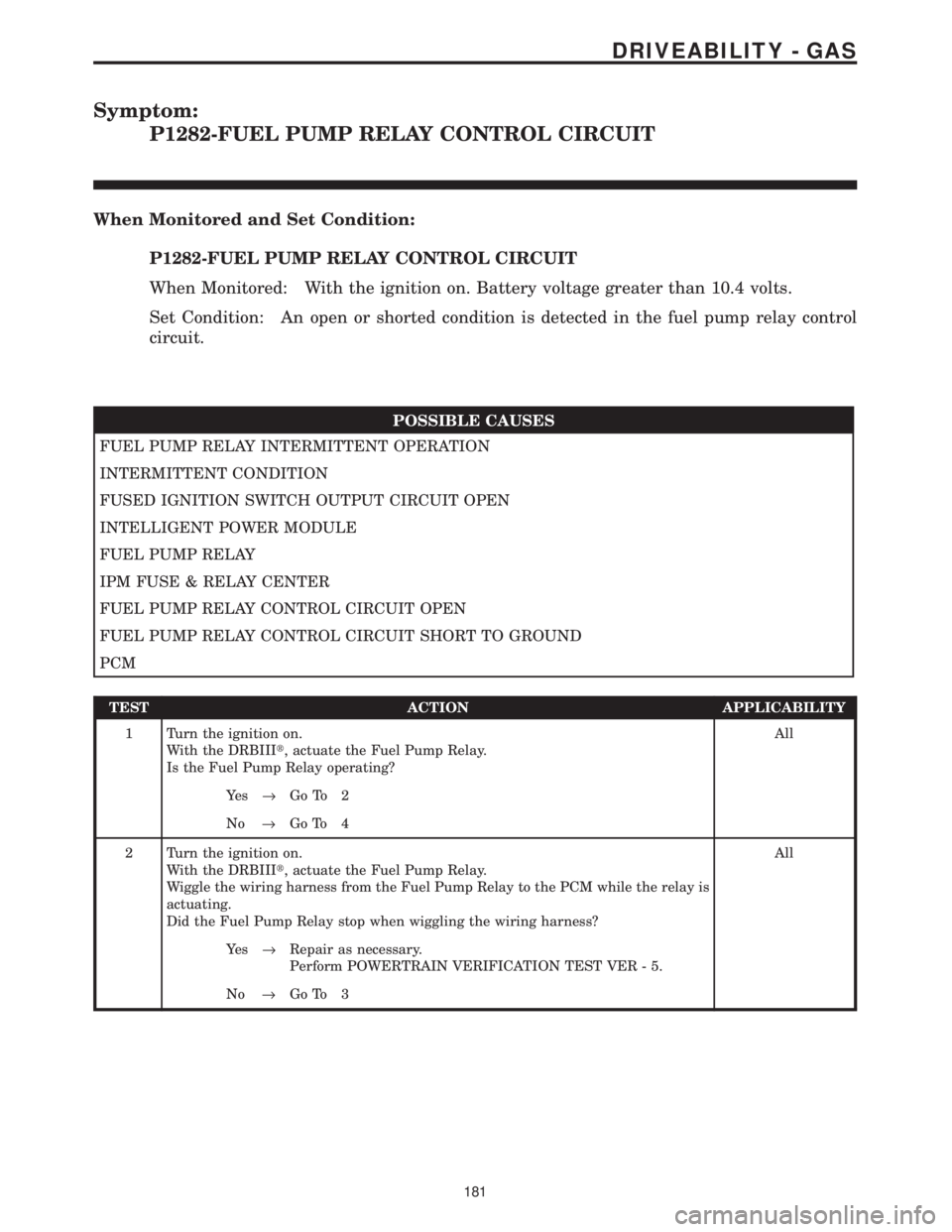
Symptom:
P1282-FUEL PUMP RELAY CONTROL CIRCUIT
When Monitored and Set Condition:
P1282-FUEL PUMP RELAY CONTROL CIRCUIT
When Monitored: With the ignition on. Battery voltage greater than 10.4 volts.
Set Condition: An open or shorted condition is detected in the fuel pump relay control
circuit.
POSSIBLE CAUSES
FUEL PUMP RELAY INTERMITTENT OPERATION
INTERMITTENT CONDITION
FUSED IGNITION SWITCH OUTPUT CIRCUIT OPEN
INTELLIGENT POWER MODULE
FUEL PUMP RELAY
IPM FUSE & RELAY CENTER
FUEL PUMP RELAY CONTROL CIRCUIT OPEN
FUEL PUMP RELAY CONTROL CIRCUIT SHORT TO GROUND
PCM
TEST ACTION APPLICABILITY
1 Turn the ignition on.
With the DRBIIIt, actuate the Fuel Pump Relay.
Is the Fuel Pump Relay operating?All
Ye s®Go To 2
No®Go To 4
2 Turn the ignition on.
With the DRBIIIt, actuate the Fuel Pump Relay.
Wiggle the wiring harness from the Fuel Pump Relay to the PCM while the relay is
actuating.
Did the Fuel Pump Relay stop when wiggling the wiring harness?All
Ye s®Repair as necessary.
Perform POWERTRAIN VERIFICATION TEST VER - 5.
No®Go To 3
181
DRIVEABILITY - GAS
Page 3976 of 4284

TEST ACTION APPLICABILITY
3WARNING: WHEN THE ENGINE IS OPERATING, DO NOT STAND IN A
DIRECT LINE WITH THE FAN. DO NOT PUT YOUR HANDS NEAR THE
PULLEYS, BELTS OR FAN. DO NOT WEAR LOOSE CLOTHING.
NOTE: The conditions that set the DTC are not present at this time. The
following list may help in identifying the intermittent condition.
With the engine running at normal operating temperature, monitor the DRB
parameters related to the DTC while wiggling the wiring harness. Look for param-
eter values to change and/or a DTC to set.
Review the DRB Freeze Frame information. If possible, try to duplicate the
conditions under which the DTC was set.
Refer to any Technical Service Bulletins (TSB) that may apply.
Visually inspect the related wiring harness. Look for any chafed, pierced, pinched, or
partially broken wires.
Visually inspect the related wiring harness connectors. Look for broken, bent, pushed
out, or corroded terminals.
Were any of the above conditions present?All
Ye s®Repair as necessary
Perform POWERTRAIN VERIFICATION TEST VER - 5.
No®Test Complete.
4 Turn the ignition off.
Remove the Fuel Pump Relay from the IPM.
Turn the ignition on.
Using a 12-volt test light connected to ground, probe the Fused Ignition Switch
circuit in the IPM.
Does the test light illuminate?All
Ye s®Go To 5
No®Go To 10
5 Turn the ignition off.
Remove the Fuel Pump Relay from the IPM.
Turn the ignition on.
Using a 12-volt test light connected to 12-volts, probe the Fuel Pump Relay Control
circuit in the IPM.
With the DRBIIIt, actuate the Fuel Pump Relay.
Does the test light flash on and off?All
Ye s®Replace the Fuel Pump Relay.
Perform POWERTRAIN VERIFICATION TEST VER - 5.
No®Go To 6
6 Turn the ignition off.
Disconnect the Intelligent Power Module C3 harness connector.
Turn the ignition on.
Using a 12-volt test light connected to 12-volts, probe the Fuel Pump Relay Control
circuit in the IPM harness connector..
With the DRBIIIt, actuate the Fuel Pump Relay.
Does the test light flash on and off?All
Ye s®Replace the IPM Fused & Relay Center.
Perform POWERTRAIN VERIFICATION TEST VER - 5.
No®Go To 7
182
DRIVEABILITY - GAS
P1282-FUEL PUMP RELAY CONTROL CIRCUIT ÐContinued
Page 3977 of 4284
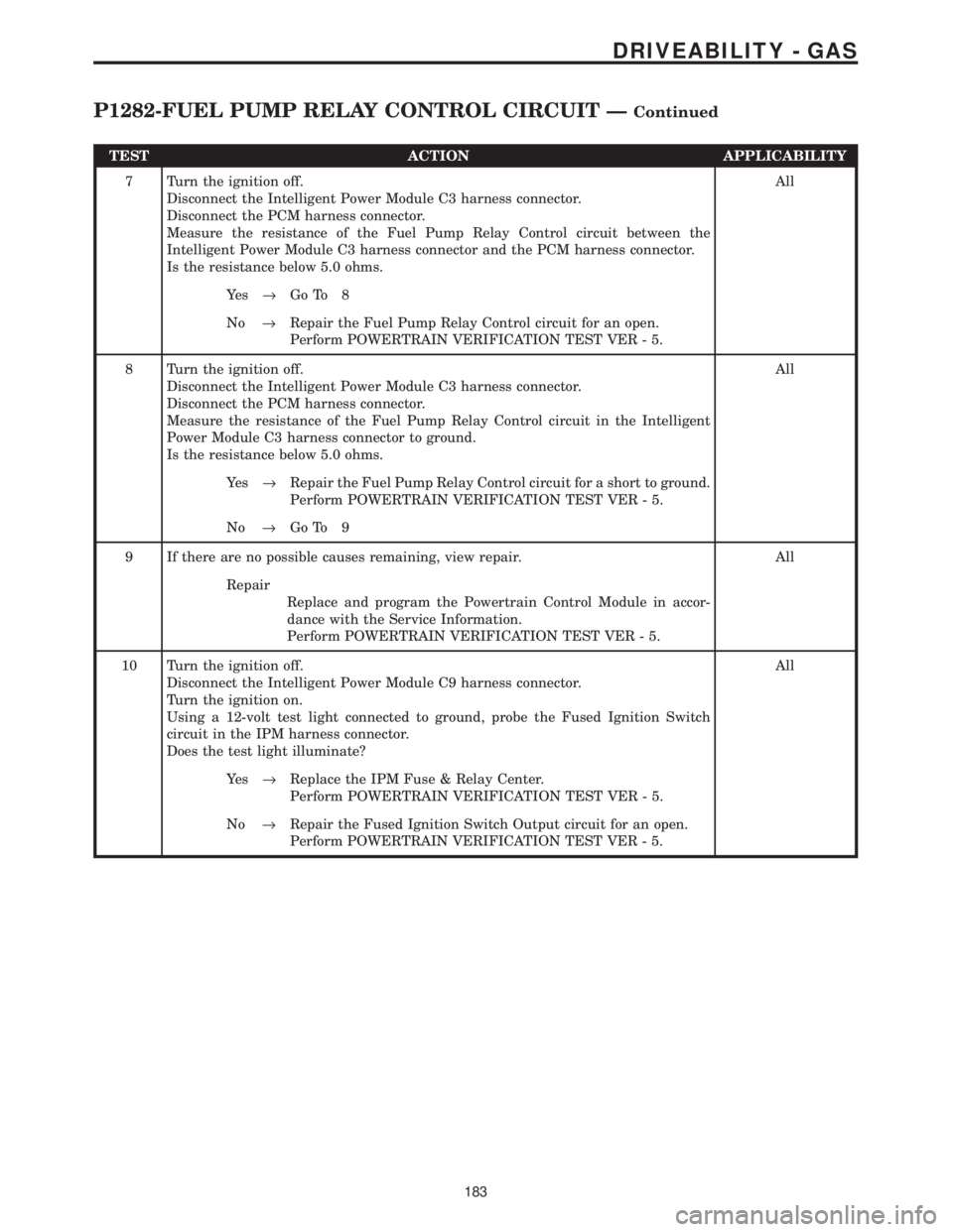
TEST ACTION APPLICABILITY
7 Turn the ignition off.
Disconnect the Intelligent Power Module C3 harness connector.
Disconnect the PCM harness connector.
Measure the resistance of the Fuel Pump Relay Control circuit between the
Intelligent Power Module C3 harness connector and the PCM harness connector.
Is the resistance below 5.0 ohms.All
Ye s®Go To 8
No®Repair the Fuel Pump Relay Control circuit for an open.
Perform POWERTRAIN VERIFICATION TEST VER - 5.
8 Turn the ignition off.
Disconnect the Intelligent Power Module C3 harness connector.
Disconnect the PCM harness connector.
Measure the resistance of the Fuel Pump Relay Control circuit in the Intelligent
Power Module C3 harness connector to ground.
Is the resistance below 5.0 ohms.All
Ye s®Repair the Fuel Pump Relay Control circuit for a short to ground.
Perform POWERTRAIN VERIFICATION TEST VER - 5.
No®Go To 9
9 If there are no possible causes remaining, view repair. All
Repair
Replace and program the Powertrain Control Module in accor-
dance with the Service Information.
Perform POWERTRAIN VERIFICATION TEST VER - 5.
10 Turn the ignition off.
Disconnect the Intelligent Power Module C9 harness connector.
Turn the ignition on.
Using a 12-volt test light connected to ground, probe the Fused Ignition Switch
circuit in the IPM harness connector.
Does the test light illuminate?All
Ye s®Replace the IPM Fuse & Relay Center.
Perform POWERTRAIN VERIFICATION TEST VER - 5.
No®Repair the Fused Ignition Switch Output circuit for an open.
Perform POWERTRAIN VERIFICATION TEST VER - 5.
183
DRIVEABILITY - GAS
P1282-FUEL PUMP RELAY CONTROL CIRCUIT ÐContinued