fuse CHRYSLER VOYAGER 2001 Service Manual
[x] Cancel search | Manufacturer: CHRYSLER, Model Year: 2001, Model line: VOYAGER, Model: CHRYSLER VOYAGER 2001Pages: 4284, PDF Size: 83.53 MB
Page 3793 of 4284
TABLE OF CONTENTS - Continued
AMBIENT TEMPERATURE SENSOR - BLACK 2 WAY........................291
AMBIENT TEMPERATURE SENSOR (SENSOR SIDE)-2WAY................292
BRAKE LAMP SWITCH - BLACK 6 WAY...................................292
BRAKE TRANSMISSION SHIFT INTERLOCK SOLENOID - BLACK 2 WAY.......292
CAMSHAFT POSITION SENSOR - BLACK 3 WAY...........................292
CLOCKSPRING C1 - WHITE 6 WAY.......................................292
CRANKSHAFT POSITION SENSOR - BLACK 3 WAY.........................293
DATA LINK CONNECTOR - WHITE 16 WAY................................293
DIAGNOSTIC JUNCTION PORT - BLACK 16 WAY...........................293
EGR SOLENOID - GRAY 2 WAY..........................................294
ENGINE COOLANT TEMPERATURE SENSOR - BLACK 2 WAY................294
ENGINE OIL PRESSURE SWITCH - LT. GREEN 2 WAY......................294
EVAP/PURGE SOLENOID - BLACK 2 WAY.................................294
FUEL INJECTOR NO. 1 - BLACK 2 WAY...................................295
FUEL INJECTOR NO. 2 - BLACK 2 WAY...................................295
FUEL INJECTOR NO. 3 - BLACK 2 WAY...................................295
FUEL INJECTOR NO. 4 - BLACK 2 WAY...................................295
FUEL INJECTOR NO. 5 (3.3L/3.8L) - BLACK 2 WAY..........................296
FUEL INJECTOR NO. 6 (3.3L/3.8L) - BLACK 2 WAY..........................296
FUEL TANK MODULE - LT. GRAY 4 WAY...................................296
GENERATOR - BLACK 2 WAY...........................................296
GENERATOR (GENERATOR SIDE).......................................297
MANIFOLD ABSOLUTE PRESSURE SENSOR - BLACK 3 WAY................297
OXYGEN SENSOR 1/1 UPSTREAM - BLACK 4 WAY.........................297
OXYGEN SENSOR 1/2 DOWNSTREAM - BLACK 4 WAY.....................297
FUSES (IPM)..........................................................299
A/C COMPRESSOR CLUTCH RELAY......................................299
ACCESSORY RELAY...................................................299
AUTOMATIC SHUTDOWN RELAY........................................300
ENGINE STARTER MOTOR RELAY.......................................300
FUEL PUMP RELAY....................................................300
POSITIVE TEMPERATURE COEFFICIENTS................................300
TRANSMISSION SAFETY SHUTDOWN RELAY.............................300
POWERTRAIN CONTROL MODULE C1 - GRAY/BLACK 40 WAY...............301
POWERTRAIN CONTROL MODULE C2 - GRAY/GRAY 40 WAY................302
10.0 SCHEMATIC DIAGRAMS................................................303
10.12001 RG 2.4L....................................................303
10.22001 RG 3.3L/3.8L................................................304
11.0 CHARTS AND GRAPHS................................................305
11.1SPECIFICATION..................................................305
v
Page 3805 of 4284
important to block the wheels on front-wheel drive
vehicles; the parking brake does not hold the drive
wheels.
When servicing a vehicle, always wear eye pro-
tection, and remove any metal jewelry such as
watchbands or bracelets that might make an inad-
vertent electrical contact.
When diagnosing a powertrain system problem,
it is important to follow approved procedures where
applicable. These procedures can be found in ser-
vice manual procedures. Following these proce-
dures is very important to the safety of individuals
performing diagnostic tests.
4.2.2 VEHICLE PREPARATION FOR
TESTING
Make sure the vehicle being tested has a fully
charged battery. If it does not, false diagnostic codes
or error messages may occur.
4.2.3 SERVICING SUB ASSEMBLIES
Some components of the powertrain system are
intended to be serviced in assembly only. Attempt-
ing to remove or repair certain system sub-
components may result in personal injury and/or
improper system operation. Only those components
with approved repair and installation procedures in
the service manual should be serviced.
4.2.4 DRBIIITSAFETY INFORMATION
WARNING: EXCEEDING THE LIMITS OF THE
DRB MULTIMETER IS DANGEROUS. IT CAN
EXPOSE YOU TO SERIOUS INJURY.
CAREFULLY READ AND UNDERSTAND THE
CAUTIONS AND THE SPECIFICATION
LIMITS.
Follow the vehicle manufacturer 's service specifi-
cations at all times.
²Do not use the DRB if it has been damaged.
²Do not use the test leads if the insulation is
damaged or if metal is exposed.
²To avoid electrical shock, do not touch the test
leads, tips, or the circuit being tested.
²Choose the proper range and function for the
measurement. Do not try voltage or current mea-
surements that may exceed the rated capacity.
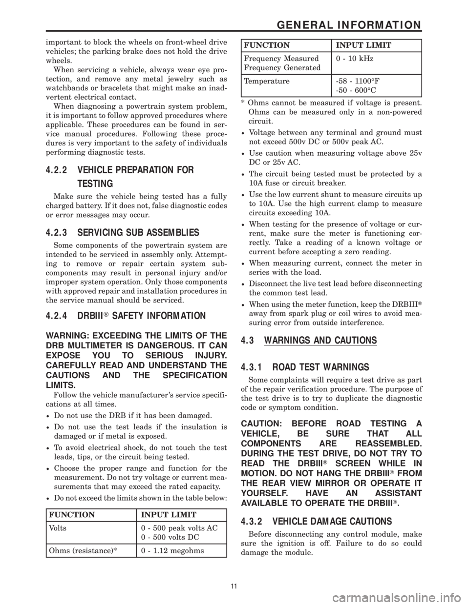
²Do not exceed the limits shown in the table below:
FUNCTION INPUT LIMIT
Volts 0 - 500 peak volts AC
0 - 500 volts DC
Ohms (resistance)* 0 - 1.12 megohms
FUNCTION INPUT LIMIT
Frequency Measured
Frequency Generated0-10kHz
Temperature -58 - 1100ÉF
-50 - 600ÉC
* Ohms cannot be measured if voltage is present.
Ohms can be measured only in a non-powered
circuit.
²Voltage between any terminal and ground must
not exceed 500v DC or 500v peak AC.
²Use caution when measuring voltage above 25v
DC or 25v AC.
²The circuit being tested must be protected by a
10A fuse or circuit breaker.
²Use the low current shunt to measure circuits up
to 10A. Use the high current clamp to measure
circuits exceeding 10A.
²When testing for the presence of voltage or cur-
rent, make sure the meter is functioning cor-
rectly. Take a reading of a known voltage or
current before accepting a zero reading.
²When measuring current, connect the meter in
series with the load.
²Disconnect the live test lead before disconnecting
the common test lead.
²When using the meter function, keep the DRBIIIt
away from spark plug or coil wires to avoid mea-
suring error from outside interference.
4.3 WARNINGS AND CAUTIONS
4.3.1 ROAD TEST WARNINGS
Some complaints will require a test drive as part
of the repair verification procedure. The purpose of
the test drive is to try to duplicate the diagnostic
code or symptom condition.
CAUTION: BEFORE ROAD TESTING A
VEHICLE, BE SURE THAT ALL
COMPONENTS ARE REASSEMBLED.
DURING THE TEST DRIVE, DO NOT TRY TO
READ THE DRBIIITSCREEN WHILE IN
MOTION. DO NOT HANG THE DRBIIITFROM
THE REAR VIEW MIRROR OR OPERATE IT
YOURSELF. HAVE AN ASSISTANT
AVAILABLE TO OPERATE THE DRBIIIT.
4.3.2 VEHICLE DAMAGE CAUTIONS
Before disconnecting any control module, make
sure the ignition is off. Failure to do so could
damage the module.
11
GENERAL INFORMATION
Page 3806 of 4284
When testing voltage or continuity at any control
module, use the terminal side (not the wire end) of
the connector. Do not probe a wire through the
insulation; this will damage it and eventually cause
it to fail because of corrosion.
Be careful when performing electrical tests so as
to prevent accidental shorting of terminals. Such
mistakes can damage fuses or components. Also, a
second DTC could be set, making diagnosis of the
original problem more difficult.
5.0 REQUIRED TOOLS AND
EQUIPMENT
DRBIIIt(diagnostic read-out box) scan tool
Evaporative System Diagnostic Kit #6917
fuel filler adapter #8382
fuel pressure adapter (C-6631) or #6539
fuel pressure kit (C-4799-B) or #5069
fuel release hose (C-4799-1)
Min Air flow fitting #6714
jumper wires
ohmmeter
oscilloscope
vacuum gauge
voltmeter
12 volt test light minimum 25 ohms resistance
with probe #6801
CAUTION: A 12 VOLT TEST LIGHT SHOULD
NOT BE USED FOR THE FOLLOWING
CIRCUITS, DAMAGE TO THE POWERTRAIN
CONTROLLER WILL OCCUR.
²5 Volt Supply
²8 Volt Supply
²J1850 PCI Bus
²CCD Bus
²CKP Sensor Signal
²CMP Sensor Signal
²Vehicle Speed Sensor Signal
²O2 Sensor Signal
6.0 GLOSSARY OF TERMS
ABSanti-lock brake system
backfire,
popbackfuel ignites in either the intake or
the exhaust system
CKPcrank position sensor
CMPcamshaft position sensorcuts out,
missesa steady pulsation or the inability of
the engine to maintain a consistent
rpm
DLCdata link connector (previously
called engine diagnostic connector)
detona-
tion,
spark
knocka mild to severe ping, especially un-
der loaded engine conditions
ECTengine coolant temperature sensor
EGRexhaust gas recirculation valve
genera-
torpreviously called alternator
hard
startThe engine takes longer than usual
to start, even though it is able to
crank normally.
hesita-
tion, sag,
stumbleThere is a momentary lack of re-
sponse when the throttle is opened.
This can occur at all vehicle speeds.
If it is severe enough, the engine
may stall.
IATintake air temperature sensor
IACidle air control motor
JTECCombined engine and transmission
control module
lack of
power,
sluggishThe engine has less than expected
power, with little or no increase in
vehicle speed when the throttle is
opened.
LDPleak detection pump
MAPmanifold absolute pressure sensor
MILmalfunction indicator lamp
MTVmanifold tuning valve
O2Soxygen sensor
PCIprogrammable communication inter-
face
PCMpowertrain control module
PCVpositive crankcase ventilation
PEPperipheral expansion port
poor fuel
economyThere is significantly less fuel mile-
age than other vehicles of the same
design ad configuration
12
GENERAL INFORMATION
Page 3824 of 4284

Symptom List:
P1696-PCM FAILURE EEPROM WRITE DENIED
P1697-PCM FAILURE SRI MILE NOT STORED
Test Note: All symptoms listed above are diagnosed using the same tests.
The title for the tests will be P1696-PCM FAILURE EEPROM
WRITE DENIED.
When Monitored and Set Condition:
P1696-PCM FAILURE EEPROM WRITE DENIED
When Monitored: Ignition key on, Continuous.
Set Condition: An attempt to program/write to the internal EEPROM failed, Also checks
at powerdown.
P1697-PCM FAILURE SRI MILE NOT STORED
When Monitored: Ignition key on, Continuous.
Set Condition: An attempt to program/write to the internal EEPROM failed, Also checks
at powerdown.
POSSIBLE CAUSES
DRB DISPLAYS WRITE FAILURE
DRB DISPLAYS WRITE REFUSED 2ND TIME
DRB DISPLAYS SRI MILEAGE INVALID
COMPARE SRI MILEAGE WITH ODOMETER
TEST ACTION APPLICABILITY
1 With the DRBIIIt, perform the SRI Memory Test.
Does the DRBIIItdisplay Write Failure?All
Ye s®Replace and program the Powertrain Control Module in accor-
dance with the Service Information.
Perform POWERTRAIN VERIFICATION TEST VER-1.
No®Go To 2
2 With the DRBIIIt, perform the SRI Memory Test.
Does the DRBIIItdisplay Write Refused?All
Ye s®Go To 3
No®Go To 4
30
COMMUNICATION
Page 3825 of 4284

TEST ACTION APPLICABILITY
3 With the DRBIIIt, perform the SRI Memory Test a second time.
NOTE: Retest the SRI Memory two more times.
Does the DRBIIItdisplay Write Refused again?All
Ye s®Replace and program the Powertrain Control Module in accor-
dance with the Service Information.
Perform POWERTRAIN VERIFICATION TEST VER-1.
No®Test Complete.
4 With the DRBIIIt, perform the SRI Memory Test.
Does the DRBIIItdisplay SRI Mileage Invalid?All
Ye s®Update the mileage and retest the SRI Memory.
Perform POWERTRAIN VERIFICATION TEST VER-1.
No®Go To 5
5 Compare the SRI Mileage stored with the Instrument Panel Odometer.
Is the mileage within the specified range displayed on the DRBIIIt?All
Ye s®Test Complete.
No®Update the mileage and retest the SRI Memory.
Perform POWERTRAIN VERIFICATION TEST VER-1.
31
COMMUNICATION
P1696-PCM FAILURE EEPROM WRITE DENIED ÐContinued
Page 3828 of 4284
Symptom:
*BUS +/- SIGNALS OPEN FROM SENTRY KEY IMMOBILIZER MODULE
POSSIBLE CAUSES
ATTEMPT TO COMMUNICATE WITH THE BCM
GROUND CIRCUIT OPEN
IGNITION SWITCH OUTPUT CIRCUIT OPEN
FUSED B(+) CIRCUIT OPEN
OPEN PCI BUS CIRCUIT
SENTRY KEY IMMOBILIZER MODULE
TEST ACTION APPLICABILITY
1 Turn the ignition on.
With the DRB, enter Body then Body Computer.
Was the DRB able to I/D or communicate with the BCM?All
Ye s®Go To 2
No®Refer to the symptom list for problems related to no communica-
tion with the BCM.
Perform SKIS VERIFICATION.
2 Turn the ignition off.
Disconnect the SKIM harness connector.
Measure the resistance between ground and the ground circuit.
Is the resistance below 5.0 ohms?All
Ye s®Go To 3
No®Repair the ground circuit for an open.
Perform SKIS VERIFICATION.
3 Turn the ignition off.
Disconnect the SKIM harness connector.
Turn the ignition on.
Using a 12-volt test light connected to ground, probe the Ignition Switch Output
circuit.
Is the test light illuminated?All
Ye s®Go To 4
No®Repair the Ignition Switch Output circuit for an open.
Perform SKIS VERIFICATION.
4 Turn the ignition off.
Disconnect the SKIM harness connector.
Using a 12-volt test light connected to ground, probe the Fused B(+) circuit.
Is the test light illuminated?All
Ye s®Go To 5
No®Repair the Fused B+ circuit for an open.
Perform SKIS VERIFICATION.
34
COMMUNICATION
Page 3918 of 4284

Symptom:
P0401 - EGR SYSTEM FAILURE
When Monitored and Set Condition:
P0401 - EGR SYSTEM FAILURE
When Monitored: With the ignition on and the battery voltage greater than 10.4 volts.
Set Condition: Conditions are met, the EGR is turned off and on momentarily. The
oxygen sensor signal is monitor for changes in its output signal during this test. If no
significant change or too much change is seen, a flag is set.
POSSIBLE CAUSES
INTERMITTENT CONDITION
EGR SOLENOID VACUUM SUPPLY
EGR VALVE OPERATION (CLOSED)
EGR VALVE OPERATION (OPEN)
FUSED IGNITION SWITCH OUTPUT CIRCUIT OPEN
EGR SOLENOID CONTROL CKT SHORTED TO VOLTAGE
EGR SOLENOID CONTROL CKT OPEN
EGR SOLENOID (CLOSED)
EGR SOLENOID CONTROL CKT SHORT TO GND
EGR SOLENOID (OPEN)
PCM
PCM (CLOSED)
TEST ACTION APPLICABILITY
1 Turn the ignition on.
With the DRBIIIt, read DTC's.
Is the Good Trip displayed and equal to zero?All
Ye s®Go To 2
No®Go To 12
2 Start the engine.
Allow the engine to reach operating temperature.
Does the engine run rough or stall at idle?All
Ye s®Go To 3
No®Go To 6
124
DRIVEABILITY - GAS
Page 3920 of 4284
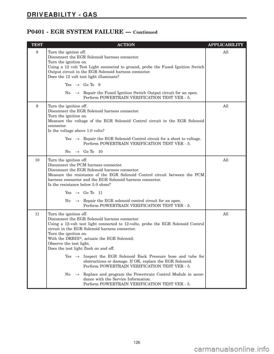
TEST ACTION APPLICABILITY
8 Turn the igntion off.
Disconnect the EGR Solenoid harness connector.
Turn the ignition on.
Using a 12 volt Test Light connected to ground, probe the Fused Ignition Switch
Output circuit in the EGR Solenoid harness connector.
Does the 12 volt test light illuminate?All
Ye s®Go To 9
No®Repair the Fused Ignition Switch Output circuit for an open.
Perform POWERTRAIN VERIFICATION TEST VER - 5.
9 Turn the ignition off.
Disconnect the EGR Solenoid harness connector.
Turn the ignition on.
Measure the voltage of the EGR Solenoid Control circuit in the EGR Solenoid
connector.
Is the voltage above 1.0 volts?All
Ye s®Repair the EGR Solenoid Control circuit for a short to voltage.
Perform POWERTRAIN VERIFICATION TEST VER - 5.
No®Go To 10
10 Turn the ignition off.
Disconnect the PCM harness connector.
Disconnect the EGR Solenoid harness connector.
Measure the resistance of the EGR Solenoid Control circuit between the PCM
harness connector and the EGR Solenoid harness connector.
Is the resistance below 5.0 ohms?All
Ye s®Go To 11
No®Repair the EGR solenoid control circuit for an open.
Perform POWERTRAIN VERIFICATION TEST VER - 5.
11 Turn the ignition off.
Disconnect the EGR Solenoid harness connector.
Using a 12-volt test light connected to 12-volts, probe the EGR Solenoid Control
circuit in the EGR Solenoid harness connector.
Turn the ignition on.
With the DRBIIIt, actuate the EGR Solenoid.
Observe the test light.
Does the test light flash on and off.All
Ye s®Inspect the EGR Solenoid Back Pressure hose and tube for
obstructions or damage. If OK, replace the EGR Solenoid.
Perform POWERTRAIN VERIFICATION TEST VER - 5.
No®Replace and program the Powertrain Control Module in accor-
dance with the Service Information.
Perform POWERTRAIN VERIFICATION TEST VER - 5.
126
DRIVEABILITY - GAS
P0401 - EGR SYSTEM FAILURE ÐContinued
Page 3922 of 4284

Symptom:
P0403 - EGR SOLENOID CIRCUIT
When Monitored and Set Condition:
P0403 - EGR SOLENOID CIRCUIT
When Monitored: Engine running. Battery voltage greater than 10 volts.
Set Condition: The EGR solenoid control circuit is not in the expected state when
requested to operate by the PCM.
POSSIBLE CAUSES
INTERMITTENT CONDITION
EGR SOLENOID
FUSED IGNITION SWITCH OUTPUT CIRCUIT OPEN
EGR SOLENOID CONTROL CKT SHORTED TO VOLTAGE
EGR SOLENOID CONTROL CKT SHORT TO GND
EGR SOLENOID CONTROL CKT OPEN
PCM
TEST ACTION APPLICABILITY
1 Turn the ignition on.
With the DRBIIIt, read DTC's.
Is the Good Trip displayed and equal to zero?All
Ye s®Go To 2
No®Go To 8
2 Turn the ignition off.
Disconnect the EGR Solenoid harness connector.
Turn the ignition on.
Turn all accessories off.
Using a 12 volt Test Light connected to the Fused Ignition Switch Output circuit,
probe the EGR Solenoid Control circuit.
With the DRB, actuate the EGR solenoid.
Does the 12 volt test light flash on and off?All
Ye s®Inspect the EGR Valve Back Pressure hose and tube for obstruc-
tions or damage. If OK, replace the EGR Solenoid.
Perform POWERTRAIN VERIFICATION TEST VER - 5.
No®Go To 3
128
DRIVEABILITY - GAS
Page 3923 of 4284
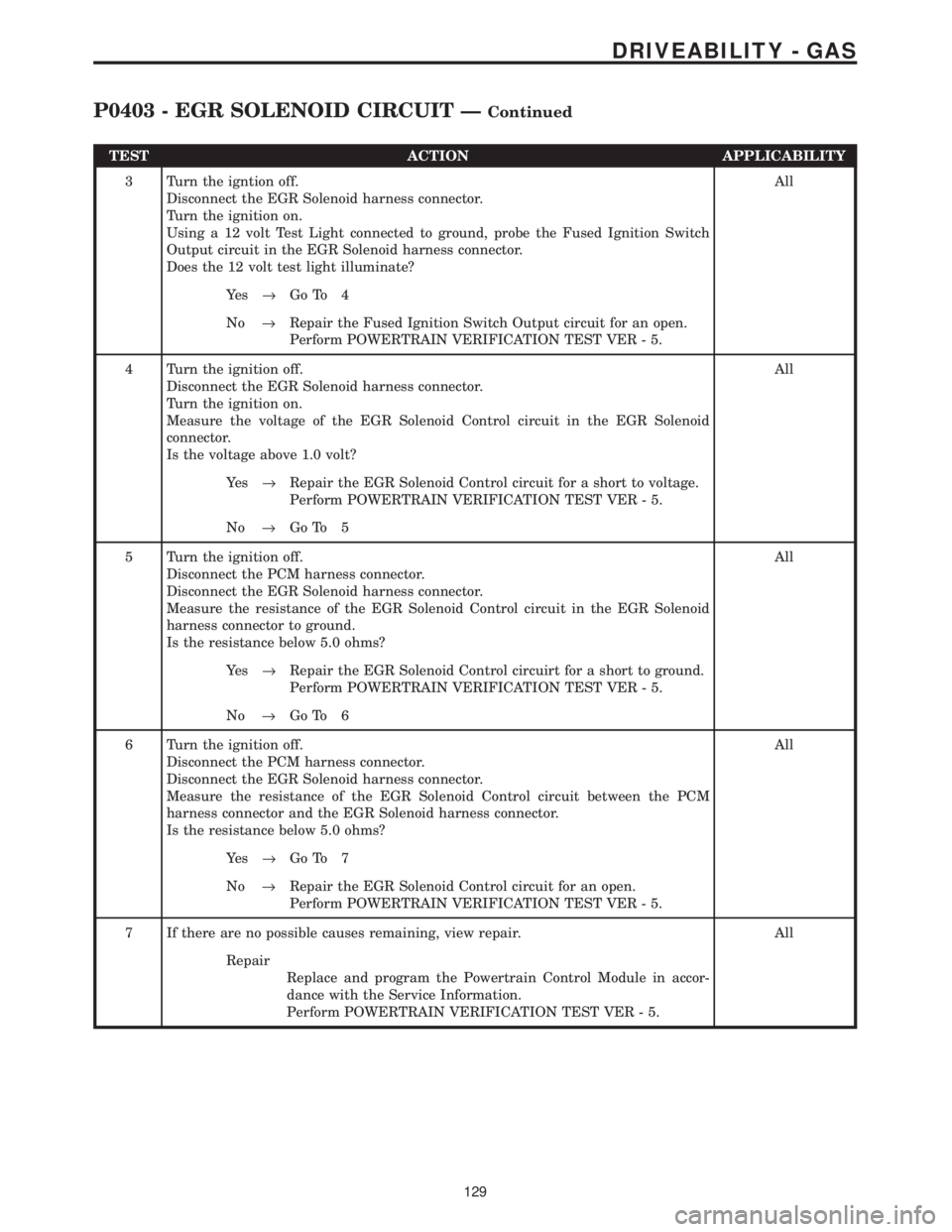
TEST ACTION APPLICABILITY
3 Turn the igntion off.
Disconnect the EGR Solenoid harness connector.
Turn the ignition on.
Using a 12 volt Test Light connected to ground, probe the Fused Ignition Switch
Output circuit in the EGR Solenoid harness connector.
Does the 12 volt test light illuminate?All
Ye s®Go To 4
No®Repair the Fused Ignition Switch Output circuit for an open.
Perform POWERTRAIN VERIFICATION TEST VER - 5.
4 Turn the ignition off.
Disconnect the EGR Solenoid harness connector.
Turn the ignition on.
Measure the voltage of the EGR Solenoid Control circuit in the EGR Solenoid
connector.
Is the voltage above 1.0 volt?All
Ye s®Repair the EGR Solenoid Control circuit for a short to voltage.
Perform POWERTRAIN VERIFICATION TEST VER - 5.
No®Go To 5
5 Turn the ignition off.
Disconnect the PCM harness connector.
Disconnect the EGR Solenoid harness connector.
Measure the resistance of the EGR Solenoid Control circuit in the EGR Solenoid
harness connector to ground.
Is the resistance below 5.0 ohms?All
Ye s®Repair the EGR Solenoid Control circuirt for a short to ground.
Perform POWERTRAIN VERIFICATION TEST VER - 5.
No®Go To 6
6 Turn the ignition off.
Disconnect the PCM harness connector.
Disconnect the EGR Solenoid harness connector.
Measure the resistance of the EGR Solenoid Control circuit between the PCM
harness connector and the EGR Solenoid harness connector.
Is the resistance below 5.0 ohms?All
Ye s®Go To 7
No®Repair the EGR Solenoid Control circuit for an open.
Perform POWERTRAIN VERIFICATION TEST VER - 5.
7 If there are no possible causes remaining, view repair. All
Repair
Replace and program the Powertrain Control Module in accor-
dance with the Service Information.
Perform POWERTRAIN VERIFICATION TEST VER - 5.
129
DRIVEABILITY - GAS
P0403 - EGR SOLENOID CIRCUIT ÐContinued