service indicator CHRYSLER VOYAGER 2001 Owner's Guide
[x] Cancel search | Manufacturer: CHRYSLER, Model Year: 2001, Model line: VOYAGER, Model: CHRYSLER VOYAGER 2001Pages: 4284, PDF Size: 83.53 MB
Page 1183 of 4284

Symptom:
RIGHT REAR WHEEL SPEED SIGNAL FAILURE
When Monitored and Set Condition:
RIGHT REAR WHEEL SPEED SIGNAL FAILURE
When Monitored: Wheel speed comparison is checked at drive off or every 7 milliseconds
(ms). Wheel speed circuit continuity is checked every 7 milliseconds. Wheel speed phase
length supervision is checked every 7 milliseconds.
Set Condition: If, during an ABS stop, the CAB commands any valve solenoid on for an
extended length of time, and does not see a corresponding wheel speed change, the
Diagnostic Trouble Code (DTC) is set. The DTC can also set if the signal is missing or
erratic.
POSSIBLE CAUSES
SENSOR OR TONE WHEEL CONCERN
DTC INTERMITTENT
RIGHT REAR WHEEL SPEED SENSOR INOPERATIVE
INTERMITTENT SIGNAL DTC
TEST ACTION APPLICABILITY
1 With the DRBIIIt, erase DTCs.
Turn the ignition off.
Start the engine.
Slowly accelerate as straight as possible from a stop to 24 km/h (15 mph).
Using the DRBIIIt, monitor the Right Rear Wheel Speed Sensor while an assistant
drives the vehicle.
With the DRBIIIt, monitor all wheel speed sensors.
Is Right Rear WSS Signal 0 km/h (0 mph) or differing from others by more than 5
km/h (3 mph)?All
Ye s®Go To 2
No®Go To 3
2 Inspect the Right Rear Wheel Speed Sensor, Connector and Tone Wheel.
NOTE: Inspect components for damage and correct installation.
Are there any visible Sensor, Connector or Tone Wheel concerns?All
Ye s®Correct the sensor, connector or tone wheel concern as necessary.
The vehicle must be driven at 25 km/h (15 mph) to extinguish the
ABS indicator.
Perform ABS VERIFICATION TEST - VER 1.
No®Replace the Left Rear Wheel Speed Sensor in accordance with the
Service Information. The vehicle must be driven at 25 km/h (15
mph) to extinguish the ABS indicator.
Perform ABS VERIFICATION TEST - VER 1.
26
BRAKES (CAB)
Page 1194 of 4284

TEST ACTION APPLICABILITY
4 Turn the ignition off.
Disconnect the TRAC OFF Switch harness connector.
Disconnect the CAB harness connector.
Turn the ignition on.
Check the TRAC OFF Switch Sense circuit for short to B+ and for an open.
Is the Sense circuit shorted or open?All
Ye s®Repair the TRAC OFF Switch Sense circuit for a short to battery
or for an open.
Perform ABS VERIFICATION TEST - VER 1.
No®Replace the Body Control Module in accordance with the Service
Information.
Perform ABS VERIFICATION TEST - VER 1.
5 Turn the ignition off.
NOTE: The purpose of this test is to perform the Instrument Cluster self
test.
Depress and hold the Odometer Reset Button.
Turn the Key from OFF to ON and then back to OFF.
Release the Odometer Reset Button.
Do the Instrument Cluster Indicators and Gauges activate and deactivate?All
Ye s®Replace the Body Control Module in accordance with the Service
Information.
Perform ABS VERIFICATION TEST - VER 1.
No®Replace the Instrument Cluster in accordance with the Service
Information.
Perform ABS VERIFICATION TEST - VER 1.
6NOTE: The purpose of this test is to perform the Instrument Cluster self
test.
Depress and hold the Odometer Reset Button.
Turn the Key from OFF to ON and then back to OFF.
Release the Odometer Reset Button.
Do the Instrument Cluster Indicators and Gauges activate and deactivate?All
Ye s®Go To 7
No®Replace the Instrument Cluster in accordance with the Service
Information.
Perform ABS VERIFICATION TEST - VER 1.
7 Turn the ignition off.
Disconnect the TRAC OFF Switch harness connector.
Turn the ignition on.
Does the TRAC OFF Indicator light and then go out?All
Ye s®Replace the TRAC OFF switch.
Perform ABS VERIFICATION TEST - VER 1.
No®Go To 8
37
BRAKES (CAB)
*TRAC OFF INDICATOR NEVER/ALWAYS ON ÐContinued
Page 1195 of 4284

TEST ACTION APPLICABILITY
8 Turn the ignition off.
Disconnect the TRAC OFF Switch harness connector.
Disconnect the BCM C4 harness connector.
Check the TRAC OFF Switch Sense circuit for short to ground.
Is the Sense circuit shorted to ground?All
Ye s®Repair the TRAC OFF Switch Sense circuit for a short to ground.
Perform ABS VERIFICATION TEST - VER 1.
No®Replace the Body Control Module in accordance with the Service
Information.
Perform ABS VERIFICATION TEST - VER 1.
38
BRAKES (CAB)
*TRAC OFF INDICATOR NEVER/ALWAYS ON ÐContinued
Page 1196 of 4284

Symptom:
*TRAC ON INDICATOR NEVER/ALWAYS ON
POSSIBLE CAUSES
CAB -- INTERNAL FAULT
CHECK TRACTION CONTROL SYSTEM
CLUSTER FAILS SELF TEST
CAB - NO TRAC MESSAGE
TEST ACTION APPLICABILITY
1NOTE: The DRBIIItmust be able to communicate with the CAB prior to
performing this test.
NOTE: Note: If any CAB DTC's are present, they must be repaired prior to
performing this test.
Perform the KEY-ON bulb test.
Did the TRAC Indicator illuminate and then go out?All
Ye s®Go To 2
No®Go To 3
2 Make sure the Traction Control system has not been deactivated with the TRAC OFF
switch.
NOTE: The purpose of this test is to determine if the Traction Control
system is operating.
With the DRBIIItin Inputs/Outputs, read the ABS Pump Motor voltage state.
Accelerate sufficient to cause drive wheel slip.
Does the TRAC Indicator illuminate and the DRBIIItdisplay approximately 9 volts?All
Ye s®The traction control system is functioning normally.
Perform ABS VERIFICATION TEST - VER 1.
No®Replace the Controller Antilock Brake in accordance with the
Service Information.
Perform ABS VERIFICATION TEST - VER 1.
3NOTE: The purpose of this test is to perform the Instrument Cluster self
test.
Depress and hold the Odometer Reset Button.
Turn the Key from OFF to ON and then back to OFF.
Release the Odometer Reset Button.
Do the Instrument Cluster Indicators and Gauges activate and deactivate?All
Ye s®Replace the Controller Antilock Brake in accordance with the
Service Information.
Perform ABS VERIFICATION TEST - VER 1.
No®Replace the Instrument Cluster in accordance with the Service
Information.
Perform ABS VERIFICATION TEST - VER 1.
39
BRAKES (CAB)
Page 1492 of 4284
CONTAINER IDENTIFICATION
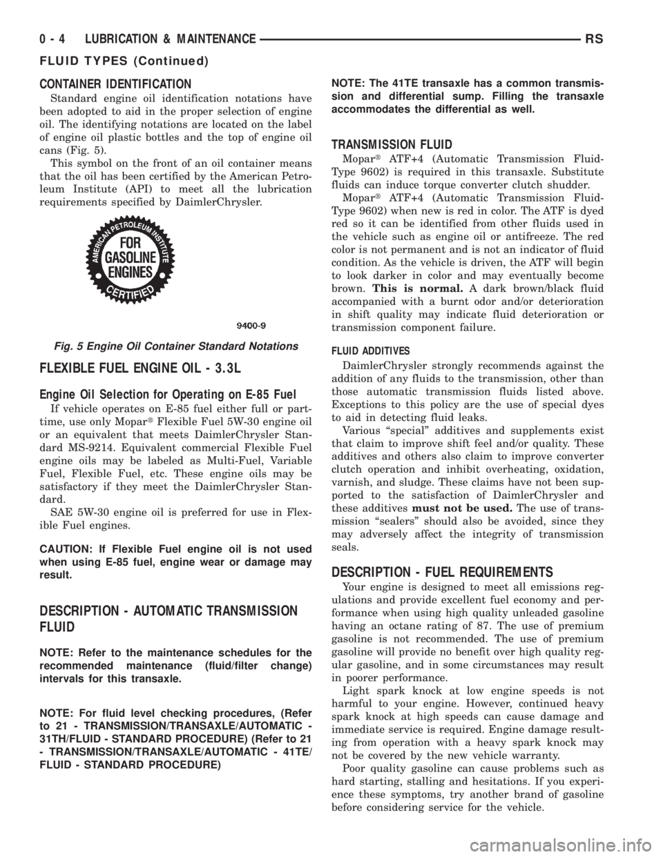
Standard engine oil identification notations have
been adopted to aid in the proper selection of engine
oil. The identifying notations are located on the label
of engine oil plastic bottles and the top of engine oil
cans (Fig. 5).
This symbol on the front of an oil container means
that the oil has been certified by the American Petro-
leum Institute (API) to meet all the lubrication
requirements specified by DaimlerChrysler.
FLEXIBLE FUEL ENGINE OIL - 3.3L
Engine Oil Selection for Operating on E-85 Fuel
If vehicle operates on E-85 fuel either full or part-
time, use only MopartFlexible Fuel 5W-30 engine oil
or an equivalent that meets DaimlerChrysler Stan-
dard MS-9214. Equivalent commercial Flexible Fuel
engine oils may be labeled as Multi-Fuel, Variable
Fuel, Flexible Fuel, etc. These engine oils may be
satisfactory if they meet the DaimlerChrysler Stan-
dard.
SAE 5W-30 engine oil is preferred for use in Flex-
ible Fuel engines.
CAUTION: If Flexible Fuel engine oil is not used
when using E-85 fuel, engine wear or damage may
result.
DESCRIPTION - AUTOMATIC TRANSMISSION
FLUID
NOTE: Refer to the maintenance schedules for the
recommended maintenance (fluid/filter change)
intervals for this transaxle.
NOTE: For fluid level checking procedures, (Refer
to 21 - TRANSMISSION/TRANSAXLE/AUTOMATIC -
31TH/FLUID - STANDARD PROCEDURE) (Refer to 21
- TRANSMISSION/TRANSAXLE/AUTOMATIC - 41TE/
FLUID - STANDARD PROCEDURE)NOTE: The 41TE transaxle has a common transmis-
sion and differential sump. Filling the transaxle
accommodates the differential as well.
TRANSMISSION FLUID
MopartATF+4 (Automatic Transmission Fluid-
Type 9602) is required in this transaxle. Substitute
fluids can induce torque converter clutch shudder.
MopartATF+4 (Automatic Transmission Fluid-
Type 9602) when new is red in color. The ATF is dyed
red so it can be identified from other fluids used in
the vehicle such as engine oil or antifreeze. The red
color is not permanent and is not an indicator of fluid
condition. As the vehicle is driven, the ATF will begin
to look darker in color and may eventually become
brown.This is normal.A dark brown/black fluid
accompanied with a burnt odor and/or deterioration
in shift quality may indicate fluid deterioration or
transmission component failure.
FLUID ADDITIVES
DaimlerChrysler strongly recommends against the
addition of any fluids to the transmission, other than
those automatic transmission fluids listed above.
Exceptions to this policy are the use of special dyes
to aid in detecting fluid leaks.
Various ªspecialº additives and supplements exist
that claim to improve shift feel and/or quality. These
additives and others also claim to improve converter
clutch operation and inhibit overheating, oxidation,
varnish, and sludge. These claims have not been sup-
ported to the satisfaction of DaimlerChrysler and
these additivesmust not be used.The use of trans-
mission ªsealersº should also be avoided, since they
may adversely affect the integrity of transmission
seals.
DESCRIPTION - FUEL REQUIREMENTS
Your engine is designed to meet all emissions reg-
ulations and provide excellent fuel economy and per-
formance when using high quality unleaded gasoline
having an octane rating of 87. The use of premium
gasoline is not recommended. The use of premium
gasoline will provide no benefit over high quality reg-
ular gasoline, and in some circumstances may result
in poorer performance.
Light spark knock at low engine speeds is not
harmful to your engine. However, continued heavy
spark knock at high speeds can cause damage and
immediate service is required. Engine damage result-
ing from operation with a heavy spark knock may
not be covered by the new vehicle warranty.
Poor quality gasoline can cause problems such as
hard starting, stalling and hesitations. If you experi-
ence these symptoms, try another brand of gasoline
before considering service for the vehicle.
Fig. 5 Engine Oil Container Standard Notations
0 - 4 LUBRICATION & MAINTENANCERS
FLUID TYPES (Continued)
Page 1493 of 4284

Over 40 auto manufacturers world-wide have
issued and endorsed consistent gasoline specifications
(the Worldwide Fuel Charter, WWFC) to define fuel
properties necessary to deliver enhanced emissions,
performance and durability for your vehicle. We rec-
ommend the use of gasolines that meet the WWFC
specifications if they are available.
REFORMULATED GASOLINE
Many areas of the country require the use of
cleaner burning gasoline referred to as ªreformulat-
edº gasoline. Reformulated gasoline contain oxygen-
ates, and are specifically blended to reduce vehicle
emissions and improve air quality.
We strongly supports the use of reformulated gas-
oline. Properly blended reformulated gasoline will
provide excellent performance and durability for the
engine and fuel system components.
GASOLINE/OXYGENATE BLENDS
Some fuel suppliers blend unleaded gasoline with
oxygenates such as 10% ethanol, MTBE, and ETBE.
Oxygenates are required in some areas of the country
during the winter months to reduce carbon monoxide
emissions. Fuels blended with these oxygenates may
be used in your vehicle.
CAUTION: DO NOT use gasoline containing METH-
ANOL. Gasoline containing methanol may damage
critical fuel system components.
MMT IN GASOLINE
MMT is a manganese-containing metallic additive
that is blended into some gasoline to increase octane.
Gasoline blended with MMT provide no performance
advantage beyond gasoline of the same octane num-
ber without MMT. Gasoline blended with MMT
reduce spark plug life and reduce emission system
performance in some vehicles. We recommend that
gasolines free of MMT be used in your vehicle. The
MMT content of gasoline may not be indicated on the
gasoline pump; therefore, you should ask your gaso-
line retailer whether or not his/her gasoline contains
MMT.
It is even more important to look for gasoline with-
out MMT in Canada because MMT can be used at
levels higher than allowed in the United States.
MMT is prohibited in Federal and California refor-
mulated gasoline.
SULFUR IN GASOLINE
If you live in the northeast United States, your
vehicle may have been designed to meet California
low emission standards with Cleaner-Burning Cali-
fornia reformulated gasoline with low sulfur. If such
fuels are not available in states adopting Californiaemission standards, your vehicles will operate satis-
factorily on fuels meeting federal specifications, but
emission control system performance may be
adversely affected. Gasoline sold outside of California
is permitted to have higher sulfur levels which may
affect the performance of the vehicle's catalytic con-
verter. This may cause the Malfunction Indicator
Lamp (MIL), Check Engine or Service Engine Soon
light to illuminate. We recommend that you try a dif-
ferent brand of unleaded gasoline having lower sulfur
to determine if the problem is fuel related prior to
returning your vehicle to an authorized dealer for
service.
CAUTION: If the Malfunction Indicator Lamp (MIL),
Check Engine or Service Engine Soon light is flash-
ing, immediate service is required; see on-board
diagnostics system section.
MATERIALS ADDED TO FUEL
All gasoline sold in the United States and Canada
are required to contain effective detergent additives.
Use of additional detergents or other additives is not
needed under normal conditions.
FUEL SYSTEM CAUTIONS
CAUTION: Follow these guidelines to maintain your
vehicle's performance:
²The use of leaded gas is prohibited by Federal
law. Using leaded gasoline can impair engine perfor-
mance, damage the emission control system, and
could result in loss of warranty coverage.
²An out-of-tune engine, or certain fuel or ignition
malfunctions, can cause the catalytic converter to
overheat. If you notice a pungent burning odor or
some light smoke, your engine may be out of tune or
malfunctioning and may require immediate service.
Contact your dealer for service assistance.
²When pulling a heavy load or driving a fully
loaded vehicle when the humidity is low and the tem-
perature is high, use a premium unleaded fuel to
help prevent spark knock. If spark knock persists,
lighten the load, or engine piston damage may result.
²The use of fuel additives which are now being
sold as octane enhancers is not recommended. Most
of these products contain high concentrations of
methanol. Fuel system damage or vehicle perfor-
mance problems resulting from the use of such fuels
or additives is not the responsibility of Daimler-
Chrysler Corporation and may not be covered under
the new vehicle warranty.
RSLUBRICATION & MAINTENANCE0-5
FLUID TYPES (Continued)
Page 1504 of 4284
Inspection and service should also be performed
anytime a malfunction is observed or suspected.
HOISTING
STANDARD PROCEDURE - HOISTING
Refer to Owner's Manual provided with vehicle for
proper emergency jacking procedures.
WARNING: THE HOISTING AND JACK LIFTING
POINTS PROVIDED ARE FOR A COMPLETE VEHI-
CLE. WHEN THE ENGINE OR REAR SUSPENSION
IS REMOVED FROM A VEHICLE, THE CENTER OF
GRAVITY IS ALTERED MAKING SOME HOISTING
CONDITIONS UNSTABLE. PROPERLY SUPPORT OR
SECURE VEHICLE TO HOISTING DEVICE WHEN
THESE CONDITIONS EXIST.
CAUTION: Do not position hoisting device on any
suspension component, including the front suspen-
sion crossmember, the rear leaf springs, and the
rear axle. Do not hoist on the front and rear
bumpers, the lower liftgate crossmember, the lower
radiator crossmember, the down standing flanges
on the sill or the front engine mount.
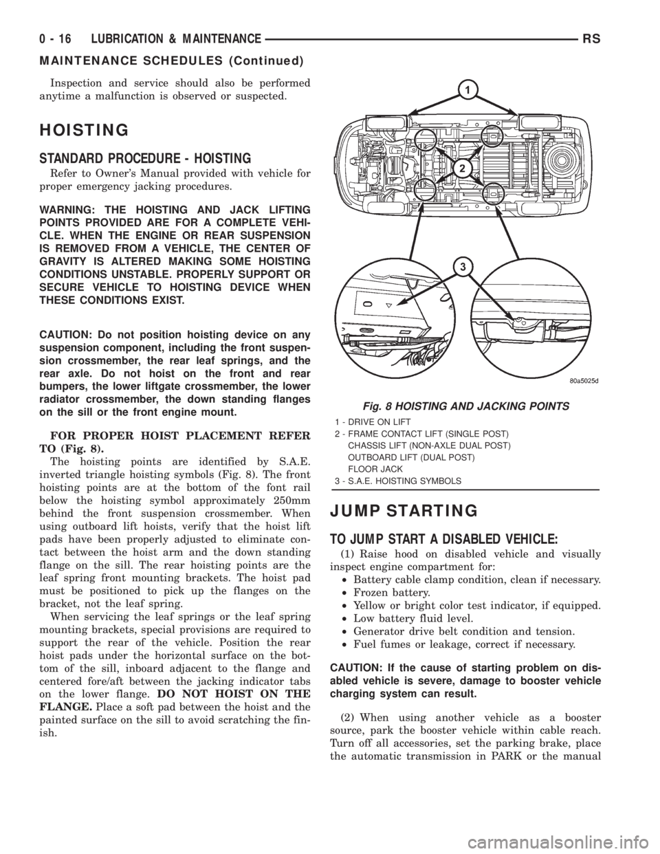
FOR PROPER HOIST PLACEMENT REFER
TO (Fig. 8).
The hoisting points are identified by S.A.E.
inverted triangle hoisting symbols (Fig. 8). The front
hoisting points are at the bottom of the font rail
below the hoisting symbol approximately 250mm
behind the front suspension crossmember. When
using outboard lift hoists, verify that the hoist lift
pads have been properly adjusted to eliminate con-
tact between the hoist arm and the down standing
flange on the sill. The rear hoisting points are the
leaf spring front mounting brackets. The hoist pad
must be positioned to pick up the flanges on the
bracket, not the leaf spring.
When servicing the leaf springs or the leaf spring
mounting brackets, special provisions are required to
support the rear of the vehicle. Position the rear
hoist pads under the horizontal surface on the bot-
tom of the sill, inboard adjacent to the flange and
centered fore/aft between the jacking indicator tabs
on the lower flange.DO NOT HOIST ON THE
FLANGE.Place a soft pad between the hoist and the
painted surface on the sill to avoid scratching the fin-
ish.
JUMP STARTING
TO JUMP START A DISABLED VEHICLE:
(1) Raise hood on disabled vehicle and visually
inspect engine compartment for:
²Battery cable clamp condition, clean if necessary.
²Frozen battery.
²Yellow or bright color test indicator, if equipped.
²Low battery fluid level.
²Generator drive belt condition and tension.
²Fuel fumes or leakage, correct if necessary.
CAUTION: If the cause of starting problem on dis-
abled vehicle is severe, damage to booster vehicle
charging system can result.
(2) When using another vehicle as a booster
source, park the booster vehicle within cable reach.
Turn off all accessories, set the parking brake, place
the automatic transmission in PARK or the manual
Fig. 8 HOISTING AND JACKING POINTS
1 - DRIVE ON LIFT
2 - FRAME CONTACT LIFT (SINGLE POST)
CHASSIS LIFT (NON-AXLE DUAL POST)
OUTBOARD LIFT (DUAL POST)
FLOOR JACK
3 - S.A.E. HOISTING SYMBOLS
0 - 16 LUBRICATION & MAINTENANCERS
MAINTENANCE SCHEDULES (Continued)
Page 1510 of 4284
MopartATF+4 (Automatic Transmission Fluid-
Type 9602) when new is red in color. The ATF is dyed
red so it can be identified from other fluids used in
the vehicle such as engine oil or antifreeze. The red
color is not permanent and is not an indicator of fluid
condition. As the vehicle is driven, the ATF will begin
to look darker in color and may eventually become
brown.This is normal.A dark brown/black fluid
accompanied with a burnt odor and/or deterioration
in shift quality may indicate fluid deterioration or
transmission component failure.
FLUID ADDITIVES
DaimlerChrysler strongly recommends against the
addition of any fluids to the transmission, other than
those automatic transmission fluids listed above.
Exceptions to this policy are the use of special dyes
to aid in detecting fluid leaks.
Various ªspecialº additives and supplements exist
that claim to improve shift feel and/or quality. These
additives and others also claim to improve converter
clutch operation and inhibit overheating, oxidation,
varnish, and sludge. These claims have not been sup-
ported to the satisfaction of DaimlerChrysler and these
additivesmust not be used.
The use of transmission
ªsealersº should also be avoided, since they may
adversely affect the integrity of transmission seals.
DESCRIPTION - FUEL REQUIREMENTS -
DIESEL ENGINE
WARNING: DO NOT USE ALCOHOL OR GASOLINE
AS A FUEL BLENDING AGENT. THEY CAN BE
UNSTABLE UNDER CERTAIN CONDITIONS AND
HAZARDOUS OR EXPLOSIVE WHEN MIXED WITH
DIESEL FUEL.
Use good quality diesel fuel from a reputable sup-
plier. For most year-round service, number 2 diesel
fuel meeting ASTM specification D-975 will provide
good performance. If the vehicle is exposed to
extreme cold (below -18ÉC/0ÉF) or is required to oper-
ate at colder than normal conditions for prolonged
periods, use climatize No. 2 diesel fuel or dilute the
No. 2 diesel fuel with 50% No. 1 diesel fuel. This will
provide better protection from fuel gelling or wax
plugging of the fuel filters.
Diesel fuel is seldom completely free of water. To
prevent fuel system trouble, including fuel line freez-
ing in winter, drain the accumulated water from the
fuel/water separator using the fuel/water separator
drain provided. If you buy good quality fuel and follow
the cold weather advice above, fuel conditioners should
not be required in your vehicle. If available in your
area, a high cetane ªpremiumº diesel fuel may offer
improved cold starting and warm up performance.
DESCRIPTION - DIESEL ENGINE OIL
API SERVICE GRADE CERTIFIED
WARNING: NEW OR USED ENGINE OIL CAN BE
IRRITATING TO THE SKIN. AVOID PROLONGED OR
REPEATED SKIN CONTACT WITH ENGINE OIL.
CONTAMINANTS IN USED ENGINE OIL, CAUSED BY
INTERNAL COMBUSTION, CAN BE HAZARDOUS TO
YOUR HEALTH. THOROUGHLY WASH EXPOSED
SKIN WITH SOAP AND WATER. DO NOT WASH
SKIN WITH GASOLINE, DIESEL FUEL, THINNER, OR
SOLVENTS, HEALTH PROBLEMS CAN RESULT. DO
NOT POLLUTE, DISPOSE OF USED ENGINE OIL
PROPERLY. CONTACT YOUR DEALER OR GOVERN-
MENT AGENCY FOR LOCATION OF COLLECTION
CENTER IN YOUR AREA.
Standard engine oil identification notations have
been adopted to aid in the proper selection of engine
oil. The identifying notations are located on the label
of engine oil plastic bottles and the top of engine oil
cans.
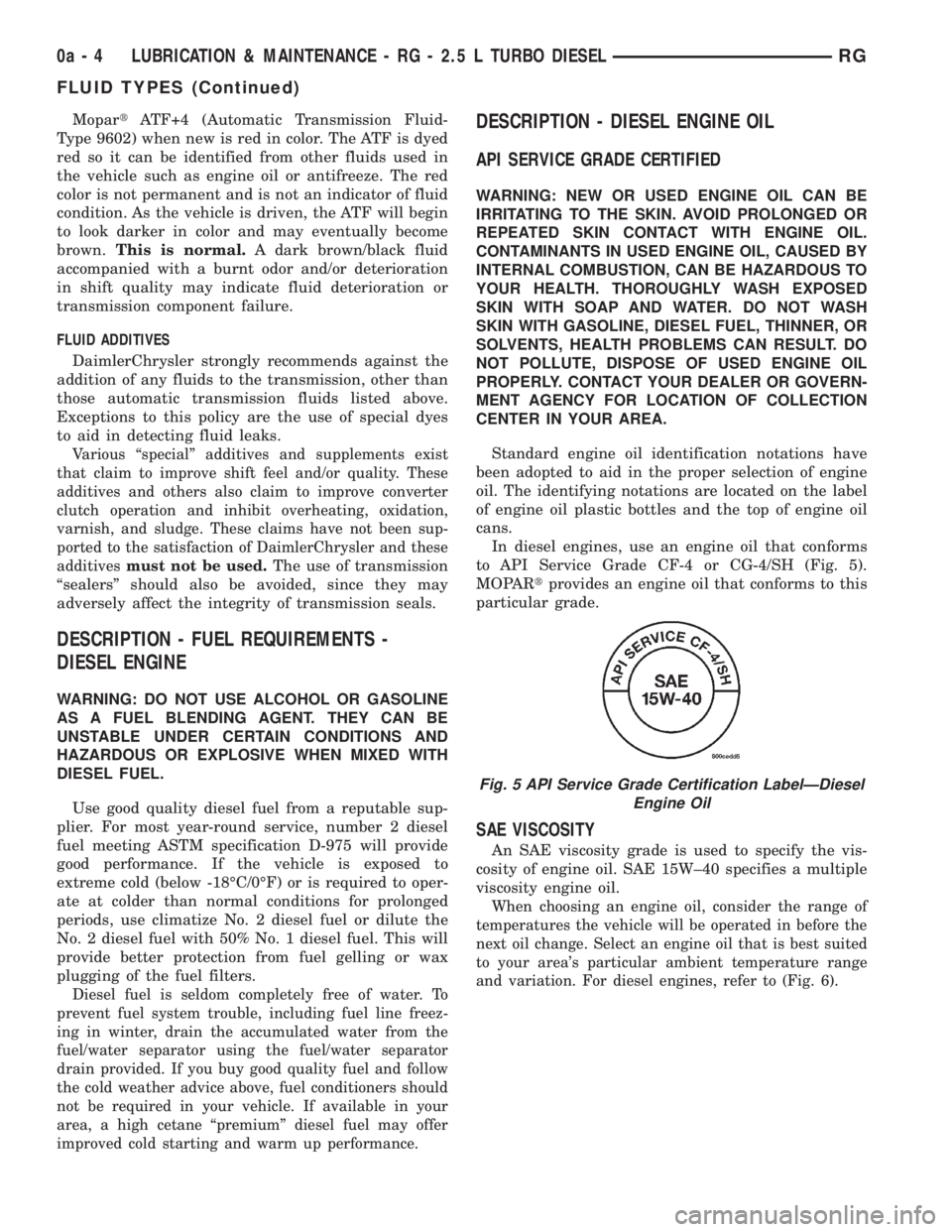
In diesel engines, use an engine oil that conforms
to API Service Grade CF-4 or CG-4/SH (Fig. 5).
MOPARtprovides an engine oil that conforms to this
particular grade.
SAE VISCOSITY
An SAE viscosity grade is used to specify the vis-
cosity of engine oil. SAE 15W±40 specifies a multiple
viscosity engine oil.
When choosing an engine oil, consider the range of
temperatures the vehicle will be operated in before the
next oil change. Select an engine oil that is best suited
to your area's particular ambient temperature range
and variation. For diesel engines, refer to (Fig. 6).
Fig. 5 API Service Grade Certification LabelÐDiesel
Engine Oil
0a - 4 LUBRICATION & MAINTENANCE - RG - 2.5 L TURBO DIESELRG
FLUID TYPES (Continued)
Page 1629 of 4284
disc/drum brakes or drum-in-hat for disc/disc brakes)
and hold it in place.
WARNING: DUST AND DIRT ACCUMULATING ON
BRAKE PARTS DURING NORMAL USE MAY CON-
TAIN ASBESTOS FIBERS FROM PRODUCTION OR
AFTERMARKET BRAKE LININGS. BREATHING
EXCESSIVE CONCENTRATIONS OF ASBESTOS
FIBERS CAN CAUSE SERIOUS BODILY HARM.
EXERCISE CARE WHEN SERVICING BRAKE
PARTS. DO NOT SAND OR GRIND BRAKE LINING
UNLESS EQUIPMENT USED IS DESIGNED TO CON-
TAIN THE DUST RESIDUE. DO NOT CLEAN BRAKE
PARTS WITH COMPRESSED AIR OR BY DRY
BRUSHING. CLEANING SHOULD BE DONE BY
DAMPENING THE BRAKE COMPONENTS WITH A
FINE MIST OF WATER, THEN WIPING THE BRAKE
COMPONENTS CLEAN WITH A DAMPENED CLOTH.
DISPOSE OF CLOTH AND ALL RESIDUE CONTAIN-
ING ASBESTOS FIBERS IN AN IMPERMEABLE
CONTAINER WITH THE APPROPRIATE LABEL. FOL-
LOW PRACTICES PRESCRIBED BY THE OCCUPA-
TIONAL SAFETY AND HEALTH ADMINISTRATION
(OSHA) AND THE ENVIRONMENTAL PROTECTION
AGENCY (EPA) FOR THE HANDLING, PROCESSING,
AND DISPOSING OF DUST OR DEBRIS THAT MAY
CONTAIN ASBESTOS FIBERS.
CAUTION: During service procedures, grease or
any other foreign material must be kept off brake
shoe assemblies, and braking surfaces of brake
rotor or drum, and external surfaces of hub and
bearing assembly.
CAUTION: Handling of brake rotors and calipers
must be done in such a way as to avoid damage to
the rotor and scratching or nicking of brake lining
on the brake shoes.
CAUTION: At no time when servicing a vehicle, can
a sheet metal screw, bolt or other metal fastener be
installed in the shock tower to take the place of an
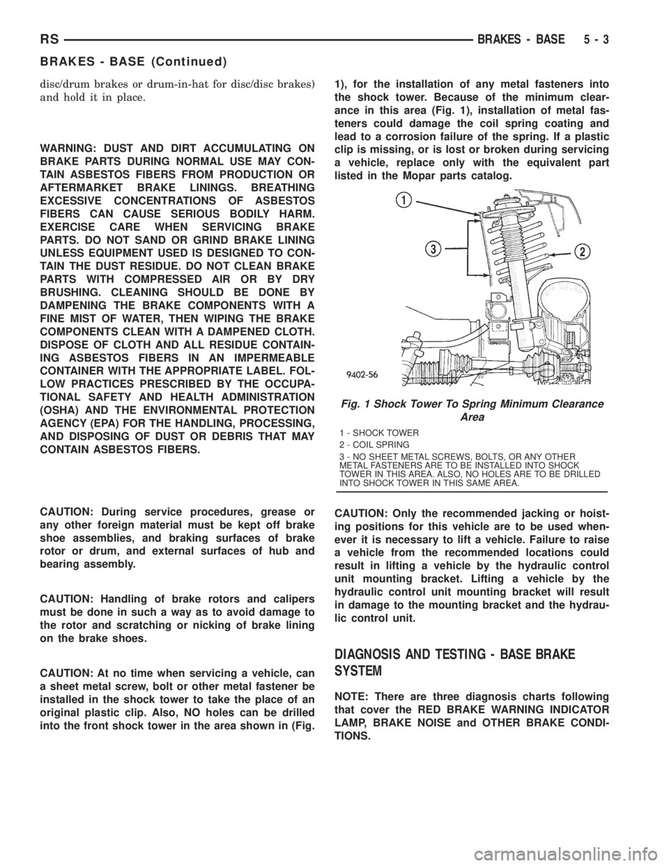
original plastic clip. Also, NO holes can be drilled
into the front shock tower in the area shown in (Fig.1), for the installation of any metal fasteners into
the shock tower. Because of the minimum clear-
ance in this area (Fig. 1), installation of metal fas-
teners could damage the coil spring coating and
lead to a corrosion failure of the spring. If a plastic
clip is missing, or is lost or broken during servicing
a vehicle, replace only with the equivalent part
listed in the Mopar parts catalog.
CAUTION: Only the recommended jacking or hoist-
ing positions for this vehicle are to be used when-
ever it is necessary to lift a vehicle. Failure to raise
a vehicle from the recommended locations could
result in lifting a vehicle by the hydraulic control
unit mounting bracket. Lifting a vehicle by the
hydraulic control unit mounting bracket will result
in damage to the mounting bracket and the hydrau-
lic control unit.
DIAGNOSIS AND TESTING - BASE BRAKE
SYSTEM
NOTE: There are three diagnosis charts following
that cover the RED BRAKE WARNING INDICATOR
LAMP, BRAKE NOISE and OTHER BRAKE CONDI-
TIONS.
Fig. 1 Shock Tower To Spring Minimum Clearance
Area
1 - SHOCK TOWER
2 - COIL SPRING
3 - NO SHEET METAL SCREWS, BOLTS, OR ANY OTHER
METAL FASTENERS ARE TO BE INSTALLED INTO SHOCK
TOWER IN THIS AREA. ALSO, NO HOLES ARE TO BE DRILLED
INTO SHOCK TOWER IN THIS SAME AREA.
RSBRAKES - BASE5-3
BRAKES - BASE (Continued)
Page 1693 of 4284
BRAKES - ABS
TABLE OF CONTENTS
page page
BRAKES - ABS
DESCRIPTION...........................67
OPERATION.............................67
CAUTION...............................69
STANDARD PROCEDURE..................70
ANTILOCK BRAKE SYSTEM BLEEDING.....70
SPECIFICATIONS........................71
FRONT WHEEL SPEED SENSOR
REMOVAL..............................71
INSTALLATION...........................71
REAR WHEEL SPEED SENSOR - AWD
REMOVAL..............................72
INSTALLATION...........................72
REAR WHEEL SPEED SENSOR - FWD
REMOVAL..............................73INSTALLATION...........................74
TONE WHEEL
INSPECTION............................74
TRACTION CONTROL SWITCH
DIAGNOSIS AND TESTING.................74
TRACTION CONTROL SWITCH............74
ICU (INTEGRATED CONTROL UNIT)
DESCRIPTION...........................75
OPERATION.............................75
REMOVAL..............................76
DISASSEMBLY...........................77
ASSEMBLY.............................77
INSTALLATION...........................77
BRAKES - ABS
DESCRIPTION - ANTILOCK BRAKE SYSTEM
This section covers the physical and operational
descriptions and the on-car service procedures for the
Mark 20e Antilock Brake System and the Mark 20e
Antilock Brake System with traction control.
The purpose of the antilock brake system (ABS) is
to prevent wheel lockup under braking conditions on
virtually any type of road surface. Antilock braking is
desirable because a vehicle that is stopped without
locking the wheels retains directional stability and
some steering capability. This allows the driver to
retain greater control of the vehicle during braking.
DESCRIPTION - ELECTRONIC BRAKE
DISTRIBUTION
Vehicles equipped with ABS use electronic brake
distribution (EBD) to balance front-to-rear braking.
The EBD is used in place of a rear proportioning
valve. The EBD system uses the ABS system to con-
trol the slip of the rear wheels in partial braking
range. The braking force of the rear wheels is con-
trolled electronically by using the inlet and outlet
valves located in the integrated control unit (ICU).
DESCRIPTION - TRACTION CONTROL SYSTEM
Traction control reduces wheel slip and maintains
traction at the driving wheels at speeds below 56
km/h (35 mph) when road surfaces are slippery. The
traction control system reduces wheel slip by braking
the wheel that is losing traction.
HYDRAULIC SHUTTLE VALVES
Two pressure relief hydraulic shuttle valves are
included on vehicles with traction control. These
valves are located inside the HCU and cannot be ser-
viced separately from the HCU.
TRACTION CONTROL LAMP
The traction control function lamp is located in the
transmission range indicator display of the instru-
ment cluster, displaying TRAC, TRAC OFF or nei-
ther depending on system mode.
The TRAC OFF lamp is controlled by a Traction
Control Off switch that is a momentary contact type
switch. The Traction Control Off switch is located on
the steering column upper shroud.
OPERATION - ANTILOCK BRAKE SYSTEM
There are a few performance characteristics of the
Mark 20e Antilock Brake System that may at first
seem abnormal, but in fact are normal. These char-
acteristics are described below.
NORMAL BRAKING
Under normal braking conditions, the ABS func-
tions the same as a standard base brake system with
a diagonally split master cylinder and conventional
vacuum assist.
ABS BRAKING
ABS operation is available at all vehicle speeds
above 3±5 mph. If a wheel locking tendency is
detected during a brake application, the brake sys-
RSBRAKES - ABS5-67