service indicator CHRYSLER VOYAGER 2001 Workshop Manual
[x] Cancel search | Manufacturer: CHRYSLER, Model Year: 2001, Model line: VOYAGER, Model: CHRYSLER VOYAGER 2001Pages: 4284, PDF Size: 83.53 MB
Page 1695 of 4284
the rear brake pressure, the outlet valve is switched
off and the inlet valve is pulsed. This increases the
pressure to the rear brakes. This back-and-forth pro-
cess will continue until the required slip difference is
obtained. At the end of EBD braking (brakes
released) the fluid in the LPA drains back to the
master cylinder by switching on the outlet valve and
draining through the inlet valve check valve. At the
same time the inlet valve is switched on in case of
another brake application.
The EBD will remain functional during many ABS
fault modes. If both the red BRAKE, and amber ABS
warning indicators are illuminated, the EBD may not
be functioning.
OPERATION - TRACTION CONTROL SYSTEM
The traction control module monitors wheel speed.
During acceleration, if the module detects front
(drive) wheel slip and the brakes are not applied, the
module enters traction control mode. Traction control
operation proceeds in the following order:
(1) Close the normally open isolation valves.
(2) Start the pump/motor and supply volume and
pressure to the front (drive) hydraulic circuit. (The
pump/motor runs continuously during traction con-
trol operation.)
(3) Open and close the build and decay valves to
maintain minimum wheel slip and maximum trac-
tion.
The cycling of the build and decay valves during
traction control is similar to that during antilock
braking, except the valves work to control wheel spin
by applying the brakes, whereas the ABS function is
to control wheel skid by releasing the brakes.
If the brakes are applied at anytime during a trac-
tion control cycle, the brake lamp switch triggers the
controller to switch off traction control.
HYDRAULIC SHUTTLE VALVES
Two pressure relief hydraulic shuttle valves allow
pressure and volume to return to the master cylinder
reservoir when not consumed by the build and decay
valves. These valves are necessary because the
pump/motor supplies more volume than the system
requires.
TRACTION CONTROL LAMP
The traction control system is enabled at each igni-
tion cycle. It may be turned off by depressing the
Traction Control Off switch button when the ignition
is in the ON position. The traction control function
lamp (TRAC OFF) illuminates immediately upon
depressing the button.
The traction control function lamp illuminates dur-
ing a traction control cycle, displaying TRAC.If the CAB calculates that the brake temperatures
are high, the traction control system becomes inoper-
ative until a time-out period has elapsed. During this
ªthermo-protection mode,º the traction control func-
tion lamp illuminates TRAC OFF; note that no trou-
ble code is registered.
CAUTION
The ABS uses an electronic control module, the
CAB. This module is designed to withstand normal
current draws associated with vehicle operation.
Care must be taken to avoid overloading the CAB
circuits.
CAUTION: In testing for open or short circuits, do
not ground or apply voltage to any of the circuits
unless instructed to do so for a diagnostic proce-
dure.
CAUTION: These circuits should only be tested
using a high impedance multi-meter or the DRBIIIT
scan tool as described in this section. Power
should never be removed or applied to any control
module with the ignition in the ON position. Before
removing or connecting battery cables, fuses, or
connectors, always turn the ignition to the OFF
position.
CAUTION: The CAB 24-way connector should never
be connected or disconnected with the ignition
switch in the ON position.
CAUTION: Use only factory wiring harnesses. Do
not cut or splice wiring to the brake circuits. The
addition of aftermarket electrical equipment (car
phone, radar detector, citizen band radio, trailer
lighting, trailer brakes, etc.) on a vehicle equipped
with antilock brakes may affect the function of the
antilock brake system.
CAUTION: When performing any service procedure
on a vehicle equipped with ABS, do not apply a
12-volt power source to the ground circuit of the
pump motor in the HCU. Doing this will damage the
pump motor and will require replacement of the
entire HCU.
CAUTION: An attempt to remove or disconnect cer-
tain system components may result in improper
system operation. Only those components with
approved removal and installation procedures in
this manual should be serviced.
RSBRAKES - ABS5-69
BRAKES - ABS (Continued)
Page 1842 of 4284
(M) Check Engine Lamp (MIL) will illuminate during engine operation if this Diagnostic Trouble Code was recorded.
(G) Generator Lamp Illuminated
GENERIC SCAN
TOOL CODEDRB SCAN TOOL DISPLAY DESCRIPTION OF DIAGNOSTIC TROUBLE CODE
P1682 (G) Charging System Voltage Too Low Battery voltage sense input below target charging voltage
during engine operation and no significant change in voltage
detected during active test of generator output circuit.
P1683 SPD CTRL PWR Relay; or S/C 12v
Driver CKTAn open or shorted condition detected in the speed control
servo power control circuit. (SBECII: ext relay).
P1684 Battery Loss In The Last 50 Starts The battery has been disconnected within the last 50 starts.
P1685 Skim Invalid Key The engine controler has received an invalid key from the
SKIM.
P1686 No SKIM BUS Messages Received No CCD/J1850 messages received from the Smart Key
Immobilizer Module (SKIM).
P1687 No MIC BUS Message No CCD/J1850 messages received from the Mechanical
Instrument Cluster (MIC) module.
P1693 DTC Detected in Companion Module A fault has been generated in the companion engine control
module.
P1694 Fault In Companion Module No CCD/J1850 messages received from the powertrain
control module-Aisin transmission.
P1695 No CCD/J1850 Message From Body
Control ModuleNo CCD/J1850 messages received from the body control
module.
P1696 (M) PCM Failure EEPROM Write Denied Unsuccessful attempt to write to an EEPROM location by the
control module.
P1697 (M) PCM Failure SRI Mile Not Stored Unsuccessful attempt to update Service Reminder Indicator
(SRI or EMR) mileage in the control module EEPROM.
P1698 (M) No CCD/J1850 Message From TCM No CCD/J1850 messages received from the electronic
transmission control module (EATX) or the Aisin transmission
controller.
P1719 Skip Shift Solenoid Circuit An open or shorted condition detected in the transmission
2-3 gear lock-out solenoid control circuit.
P1756 GOV Press Not Equal to Target @
15-20 PSIThe requested pressure and the actual pressure are not
within a tolerance band for the Governor Control System
which is used to regulate governor pressure to control shifts
for 1st, 2nd, and 3rd gear. (Mid Pressure Malfunction)
P1757 GOV Press Not Equal to Target @
15-20 PSIThe requested pressure and the actual pressure are not
within a tolerance band for the Governor Control System
which is used to regulate governor pressure to control shifts
for 1st, 2nd, and 3rd gear (Zero Pressure Malfunction)
P1762 Gov Press Sen Offset Volts Too Low
or HighThe Governor Pressure Sensor input is greater than a
calibration limit or is less than a calibration limit for 3
consecutive park/neutral calibrations.
P1763 Governor Pressure Sensor Volts Too
HiThe Governor Pressure Sensor input is above an acceptable
voltage level.
P1764 Governor Pressure Sensor Volts Too
LowThe Governor Pressure Sensor input is below an acceptable
voltage level.
P1765 Trans 12 Volt Supply Relay CTRL
CircuitAn open or shorted condition is detected in the Transmission
Relay control circuit. This relay supplies power to the TCC>
P1899 (M) P/N Switch Stuck in Park or in Gear Incorrect input state detected for the Park/Neutral switch.
8E - 18 ELECTRONIC CONTROL MODULESRS
POWERTRAIN CONTROL MODULE (Continued)
Page 1847 of 4284
SKIM is properly installed on the steering column,
the antenna ring fits snugly around the circumfer-
ence of the ignition lock cylinder housing. If this ring
is not mounted properly, communication problems
may arise in the form of transponder-related faults.
For added system security, each SKIM is pro-
grammed with a unique9Secret Key9code. This code
is stored in memory and is sent over the PCI bus to
the PCM and to each key that is programmed to
work with the vehicle. The9Secret Key9code is there-
fore a common element found in all components of
the Sentry Key Immobilizer System (SKIS). In the
event that a SKIM replacement is required, the
9Secret Key9code can be restored from the PCM by
following the SKIM replacement procedure found in
the DRB IIItscan tool. Proper completion of this
task will allow the existing ignition keys to be repro-
grammed. Therefore, new keys will NOT be needed.
In the event that the original9Secret Key9code can
not be recovered, new ignition keys will be required.
The DRB IIItscan tool will alert the technician if
key replacement is necessary. Another security code,
called a PIN, is used to gain secured access to the
SKIM for service. The SKIM also stores in its mem-
ory the Vehicle Identification Number (VIN), which it
learns through a bus message from the assembly
plant tester. The SKIS scrambles the information
that is communicated between its components in
order to reduce the possibility of unauthorized SKIM
access and/or disabling.
OPERATION
When the ignition switch is moved to the RUN
position, the SKIM transmits an RF signal to the
transponder in the ignition key. The SKIM then
waits for a response RF signal from the transponder
in the key. If the response received identifies the key
as valid, the SKIM sends a9valid key9message to
the PCM over the PCI bus. If the response received
identifies the key as invalid or no response is
received from the transponder in the ignition key, the
SKIM sends an9invalid key9message to the PCM.
The PCM will enable or disable engine operation
based upon the status of the SKIM messages. It is
important to note that the default condition in the
PCM is9invalid key.9Therefore, if no response is
received by the PCM, the engine will be immobilized
after two (2) seconds of running.
The SKIM also sends indicator light status mes-
sages to the BCM to operate the light. This is the
method used to turn the light ON solid or to flash it
after the indicator light test is complete to signify a
fault in the SKIS. If the light comes ON and stays
ON solid after the indicator light test, this signifies
that the SKIM has detected a system malfunction
and/or that the SKIS has become inoperative. If theSKIM detects an invalid keyORa key-related fault
exists, the indicator light will flash following the
indicator light test. The SKIM may also request an
audible chime if the customer key programming fea-
ture is available and the procedure is being utilized.
Refer to Electrical, Vehicle Theft Security, Transpon-
der Key, Standard Procedure - Transponder Program-
ming.
REMOVAL
(1) Disconnect and isolate the battery negative
cable.
(2) Remove Lower Instrument Panel Cover. Refer
to Body, Instrument Panel, Lower Instrument Panel
Cover, Removal.
(3) Remove the steering column upper and lower
shrouds. Refer to Steering, Column, Column Shroud,
Removal.
(4) Disengage the steering column wire harness
from the Sentry Key Immobilizer Module (SKIM).
(5) Remove the one screws securing the SKIM to
the steering column.
(6) Rotate the SKIM upwards and then to the side
away from the steering column to slide the SKIM
antenna ring from around the ignition switch lock
cylinder housing.
(7) Remove the SKIM from the vehicle.
INSTALLATION
(1) Slip the SKIM antenna ring around the igni-
tion switch lock cylinder housing. Rotate the SKIM
downwards and then towards the steering column.
(2) Install the one screws securing the SKIM to
the steering column.
(3) Engage the steering column wire harness from
the Sentry Key Immobilizer Module (SKIM).
(4) Install the steering column upper and lower
shrouds. Refer to Steering, Column, Column Shroud,
Installation.
(5) Install the Lower Instrument Panel Cover.
Refer to Body, Instrument Panel, Lower Instrument
Panel Cover, Installation.
(6) Connect the battery negative cable.
SLIDING DOOR CONTROL
MODULE
DESCRIPTION
Vehicles equipped with a power sliding door utilize
a sliding door control module. The sliding door con-
trol module is located behind the sliding door trim
panel in the center of the door, just above the sliding
door motor. This module controls the operation of the
door through the Programmable Communication
Interface (PCI) J1850 data bus circuit and the Body
RSELECTRONIC CONTROL MODULES8E-23
SENTRY KEY IMMOBILIZER MODULE (Continued)
Page 1861 of 4284
material protrude from the top of the molded plastic
battery case to provide the means for connecting the
battery to the vehicle electrical system. The battery
positive terminal post is visibly larger in diameter
than the negative terminal post, for easy identification.
The lettersPOS
andNEGare also molded into the
top of the battery case adjacent to their respective
positive and negative terminal posts for additional
identification confirmation. Refer toBattery Cables
in the index of this service manual for the location of
more information on the battery cables that connect
the battery to the vehicle electrical system.
This battery is designed to provide a safe, efficient
and reliable means of storing electrical energy in a
chemical form. This means of energy storage allows
the battery to produce the electrical energy required
to operate the engine starting system, as well as to
operate many of the other vehicle accessory systems
for limited durations while the engine and/or the
charging system are not operating. The battery is
made up of six individual cells that are connected in
series. Each cell contains positively charged plate
groups that are connected with lead straps to the
positive terminal post, and negatively charged plate
groups that are connected with lead straps to the
negative terminal post. Each plate consists of a stiff
mesh framework or grid coated with lead dioxide
(positive plate) or sponge lead (negative plate). Insu-
lators or plate separators made of a non-conductive
material are inserted between the positive and nega-
tive plates to prevent them from contacting or short-
ing against one another. These dissimilar metal
plates are submerged in a sulfuric acid and water
solution called an electrolyte.
Some factory-installed batteries have a built-in test
indicator (hydrometer). The color visible in the sight
glass of the indicator will reveal the battery condi-
tion. For more information on the use of the built-in
test indicator, refer toStandard Procedures The
factory-installed low-maintenance battery has
removable battery cell caps.Distilled water can
be added to this battery. The battery is not sealed
and has vent holes in the cell caps. The chemical
composition of the metal coated plates within the
low-maintenance battery reduces battery gassing and
water loss, at normal charge and discharge rates.
Therefore, the battery should not require additional
water in normal service. If the electrolyte level in
this battery does become low, distilled water must be
added. However, rapid loss of electrolyte can be
caused by an overcharging condition. Be certain to
diagnose the charging system after replenishing the
water in the battery for a low electrolyte condition
and before returning the vehicle to service. Refer to
Charging Systemfor additional information.The battery Group Size number, the Cold Cranking
Amperage (CCA) rating, and the Reserve Capacity
(RC) rating or Ampere-Hours (AH) rating can be
found on the original equipment battery label. Be
certain that a replacement battery has the correct
Group Size number, as well as CCA, and RC or AH
ratings that equal or exceed the original equipment
specification for the vehicle being serviced. Refer to
Battery Specificationsin this group for the loca-
tion of the proper factory-installed battery specifica-
tions. Battery sizes and ratings are discussed in more
detail below.
Group Size
²The outside dimensions and terminal placement
of the battery conform to standards established by
the Battery Council International (BCI). Each bat-
tery is assigned a BCI Group Size number to help
identify a correctly-sized replacement.
Cold Cranking Amperage
²The Cold Cranking Amperage (CCA) rating spec-
ifies how much current (in amperes) the battery can
deliver for thirty seconds at -18É C (0É F). Terminal
voltage must not fall below 7.2 volts during or after
the thirty second discharge period. The CCA required
is generally higher as engine displacement increases,
depending also upon the starter current draw
requirements.
Reserve Capacity
²The Reserve Capacity (RC) rating specifies the
time (in minutes) it takes for battery terminal volt-
age to fall below 10.5 volts, at a discharge rate of 25
amperes. RC is determined with the battery fully-
charged at 26.7É C (80É F). This rating estimates how
long the battery might last after a charging system
failure, under minimum electrical load.
Ampere-Hours
²The Ampere-Hours (AH) rating specifies the cur-
rent (in amperes) that a battery can deliver steadily
for twenty hours, with the voltage in the battery not
falling below 10.5 volts. This rating is also sometimes
identified as the twenty-hour discharge rating.
OPERATION
The battery is designed to store electrical energy in
a chemical form. When an electrical load is applied to
the terminals of the battery, an electrochemical reac-
tion occurs. This reaction causes the battery to dis-
charge electrical current from its terminals. As the
RSBATTERY SYSTEM8F-7
BATTERY (Continued)
Page 1863 of 4284
to determine its cranking capacity. A battery that is
fully-charged, but does not pass the load test, is
faulty and must be replaced.
NOTE: Completely discharged batteries may take
several hours to accept a charge. Refer to Standard
Procedures for the proper battery charging proce-
dures.
A battery is fully-charged when:
²All battery cells are gassing freely during charg-
ing.
²A green color is visible in the sight glass of the
battery built-in test indicator.
²Three corrected specific gravity tests, taken at
one-hour intervals, indicate no increase in the spe-
cific gravity of the battery electrolyte.
²Open-circuit voltage of the battery is 12.4 volts
or greater.
STANDARD PROCEDURE - CHECKING BATTERY
ELECTROLYTE LEVEL
The following procedure can be used to check the
electrolyte level in the battery.
(1) Remove the battery caps.
(2) Look through the battery cap holes to deter-
mine the level of the electrolyte in the battery. The
electrolyte should be approximately 1 centimeter
above the battery plates or until the hook inside the
battery cap holes is covered.
(3) Add only distilled water until the electrolyte
level is approx. one centimeter above the plates.
STANDARD PROCEDURE - BATTERY
CHARGING
Battery charging is the means by which the bat-
tery can be restored to its full voltage potential. A
battery is fully-charged when:
²All of the battery cells are gassing freely during
battery charging.
²A green color is visible in the sight glass of the
battery built-in test indicator.
²Three hydrometer tests, taken at one-hour inter-
vals, indicate no increase in the temperature-cor-
rected specific gravity of the battery electrolyte.
²Open-circuit voltage of the battery is 12.4 volts
or above.
WARNING: NEVER EXCEED TWENTY AMPERES
WHEN CHARGING A COLD (-1É C [30É F] OR
LOWER) BATTERY. THE BATTERY MAY ARC INTER-
NALLY AND EXPLODE. PERSONAL INJURY AND/OR
VEHICLE DAMAGE MAY RESULT.
WARNING: IF THE BATTERY SHOWS SIGNS OF
FREEZING, LEAKING, LOOSE POSTS, DO NOTTEST, ASSIST-BOOST, OR CHARGE. THE BATTERY
MAY ARC INTERNALLY AND EXPLODE. PERSONAL
INJURY AND/OR VEHICLE DAMAGE MAY RESULT.
WARNING: EXPLOSIVE HYDROGEN GAS FORMS IN
AND AROUND THE BATTERY. DO NOT SMOKE,
USE FLAME, OR CREATE SPARKS NEAR THE BAT-
TERY. PERSONAL INJURY AND/OR VEHICLE DAM-
AGE MAY RESULT.
WARNING: THE BATTERY CONTAINS SULFURIC
ACID, WHICH IS POISONOUS AND CAUSTIC. AVOID
CONTACT WITH THE SKIN, EYES, OR CLOTHING.
IN THE EVENT OF CONTACT, FLUSH WITH WATER
AND CALL A PHYSICIAN IMMEDIATELY. KEEP OUT
OF THE REACH OF CHILDREN.
WARNING: IF THE BATTERY IS EQUIPPED WITH
REMOVABLE CELL CAPS, BE CERTAIN THAT EACH
OF THE CELL CAPS IS IN PLACE AND TIGHT
BEFORE THE BATTERY IS RETURNED TO SER-
VICE. PERSONAL INJURY AND/OR VEHICLE DAM-
AGE MAY RESULT FROM LOOSE OR MISSING
CELL CAPS.
CAUTION: Always disconnect and isolate the bat-
tery negative cable before charging a battery. Do
not exceed sixteen volts while charging a battery.
Damage to the vehicle electrical system compo-
nents may result.
CAUTION: Battery electrolyte will bubble inside the
battery case during normal battery charging. Elec-
trolyte boiling or being discharged from the battery
vents indicates a battery overcharging condition.
Immediately reduce the charging rate or turn off the
charger to evaluate the battery condition. Damage
to the battery may result from overcharging.
CAUTION: The battery should not be hot to the
touch. If the battery feels hot to the touch, turn off
the charger and let the battery cool before continu-
ing the charging operation. Damage to the battery
may result.
After the battery has been charged to 12.4 volts or
greater, perform a load test to determine the battery
cranking capacity. Refer to Standard Procedures for
the proper battery load test procedures. If the battery
will endure a load test, return the battery to service.
If the battery will not endure a load test, it is faulty
and must be replaced.
RSBATTERY SYSTEM8F-9
BATTERY (Continued)
Page 1865 of 4284
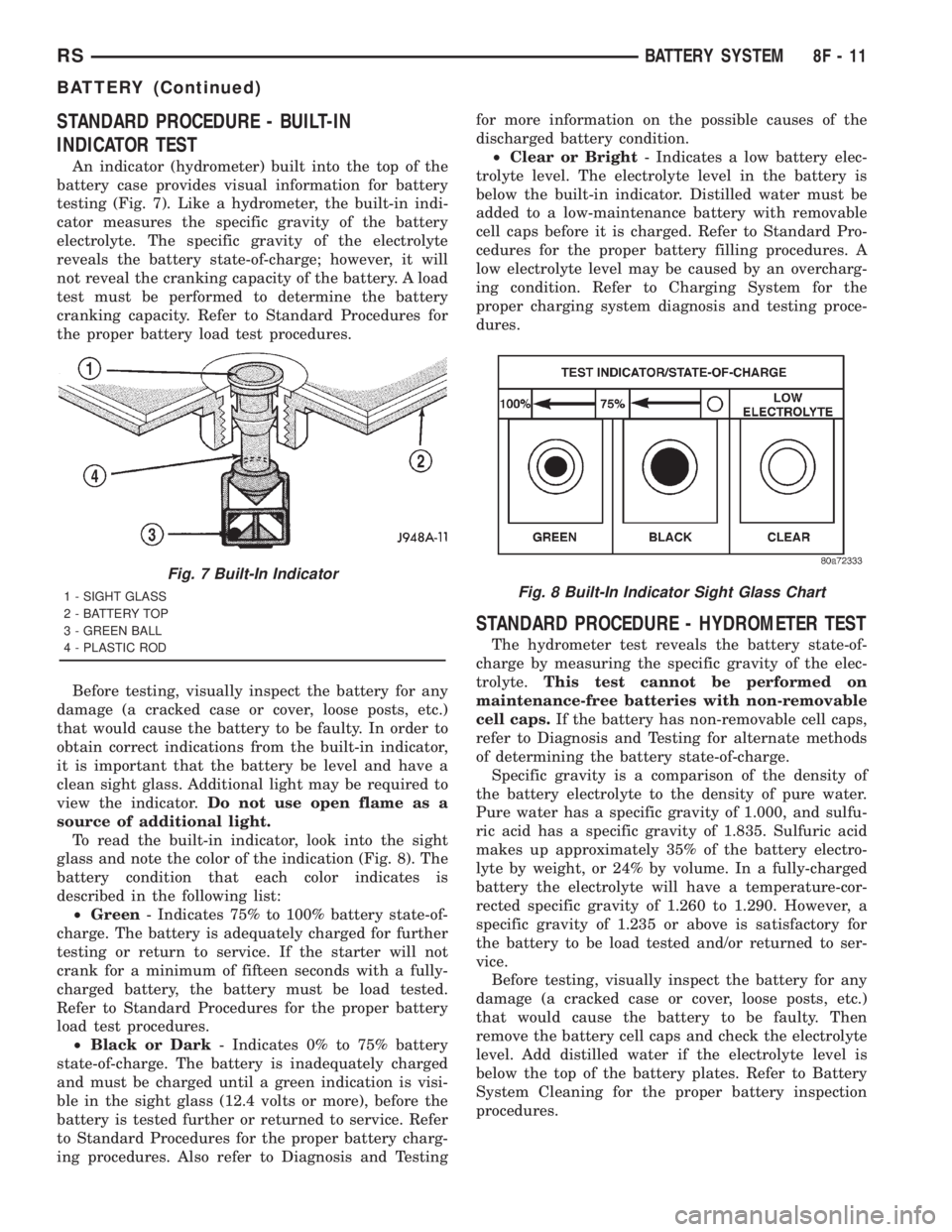
STANDARD PROCEDURE - BUILT-IN
INDICATOR TEST
An indicator (hydrometer) built into the top of the
battery case provides visual information for battery
testing (Fig. 7). Like a hydrometer, the built-in indi-
cator measures the specific gravity of the battery
electrolyte. The specific gravity of the electrolyte
reveals the battery state-of-charge; however, it will
not reveal the cranking capacity of the battery. A load
test must be performed to determine the battery
cranking capacity. Refer to Standard Procedures for
the proper battery load test procedures.
Before testing, visually inspect the battery for any
damage (a cracked case or cover, loose posts, etc.)
that would cause the battery to be faulty. In order to
obtain correct indications from the built-in indicator,
it is important that the battery be level and have a
clean sight glass. Additional light may be required to
view the indicator.Do not use open flame as a
source of additional light.
To read the built-in indicator, look into the sight
glass and note the color of the indication (Fig. 8). The
battery condition that each color indicates is
described in the following list:
²Green- Indicates 75% to 100% battery state-of-
charge. The battery is adequately charged for further
testing or return to service. If the starter will not
crank for a minimum of fifteen seconds with a fully-
charged battery, the battery must be load tested.
Refer to Standard Procedures for the proper battery
load test procedures.
²Black or Dark- Indicates 0% to 75% battery
state-of-charge. The battery is inadequately charged
and must be charged until a green indication is visi-
ble in the sight glass (12.4 volts or more), before the
battery is tested further or returned to service. Refer
to Standard Procedures for the proper battery charg-
ing procedures. Also refer to Diagnosis and Testingfor more information on the possible causes of the
discharged battery condition.
²Clear or Bright- Indicates a low battery elec-
trolyte level. The electrolyte level in the battery is
below the built-in indicator. Distilled water must be
added to a low-maintenance battery with removable
cell caps before it is charged. Refer to Standard Pro-
cedures for the proper battery filling procedures. A
low electrolyte level may be caused by an overcharg-
ing condition. Refer to Charging System for the
proper charging system diagnosis and testing proce-
dures.
STANDARD PROCEDURE - HYDROMETER TEST
The hydrometer test reveals the battery state-of-
charge by measuring the specific gravity of the elec-
trolyte.This test cannot be performed on
maintenance-free batteries with non-removable
cell caps.If the battery has non-removable cell caps,
refer to Diagnosis and Testing for alternate methods
of determining the battery state-of-charge.
Specific gravity is a comparison of the density of
the battery electrolyte to the density of pure water.
Pure water has a specific gravity of 1.000, and sulfu-
ric acid has a specific gravity of 1.835. Sulfuric acid
makes up approximately 35% of the battery electro-
lyte by weight, or 24% by volume. In a fully-charged
battery the electrolyte will have a temperature-cor-
rected specific gravity of 1.260 to 1.290. However, a
specific gravity of 1.235 or above is satisfactory for
the battery to be load tested and/or returned to ser-
vice.
Before testing, visually inspect the battery for any
damage (a cracked case or cover, loose posts, etc.)
that would cause the battery to be faulty. Then
remove the battery cell caps and check the electrolyte
level. Add distilled water if the electrolyte level is
below the top of the battery plates. Refer to Battery
System Cleaning for the proper battery inspection
procedures.
Fig. 7 Built-In Indicator
1 - SIGHT GLASS
2 - BATTERY TOP
3 - GREEN BALL
4 - PLASTIC RODFig. 8 Built-In Indicator Sight Glass Chart
RSBATTERY SYSTEM8F-11
BATTERY (Continued)
Page 1899 of 4284
WINDSHIELD GRID
DIAGNOSIS AND TESTING - SYSTEM TEST
Electrically heated rear window defogger or the
heated windshield wiper deicer operation can be
checked on the vehicle in the following manner:
(1) Turn the ignition switch to the ON position.
(2) Using a ammeter on the battery, turn the rear
defogger control switch to the ON position, a distinct
increase in amperage draw should be noted.
(3) The rear window defogger or the heated wind-
shield wiper deicer operation can be checked by feel-
ing the glass. A distinct difference in temperature
between the grid lines and adjacent clear glass can
be detected in 3 to 4 minutes of operation.
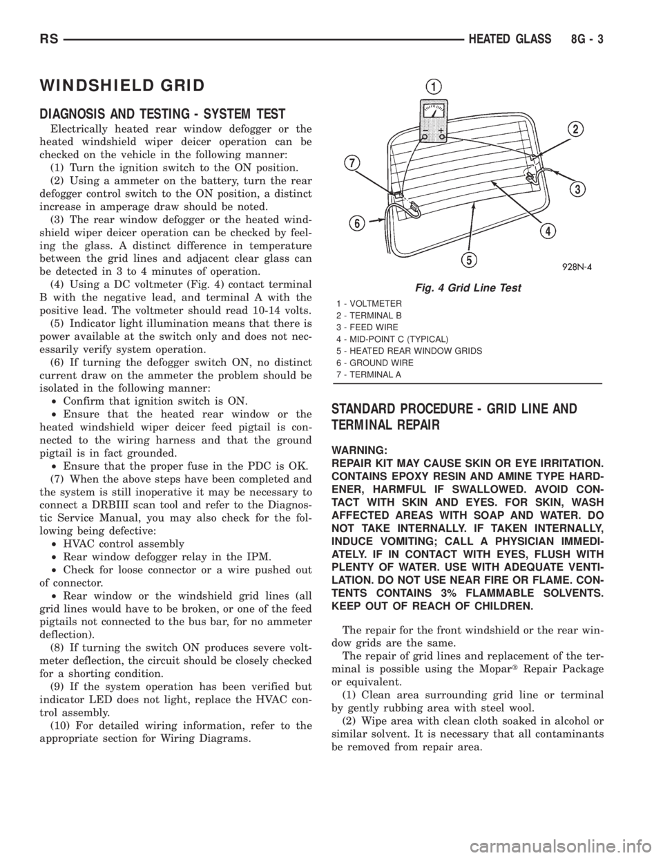
(4) Using a DC voltmeter (Fig. 4) contact terminal
B with the negative lead, and terminal A with the
positive lead. The voltmeter should read 10-14 volts.
(5) Indicator light illumination means that there is
power available at the switch only and does not nec-
essarily verify system operation.
(6) If turning the defogger switch ON, no distinct
current draw on the ammeter the problem should be
isolated in the following manner:
²Confirm that ignition switch is ON.
²Ensure that the heated rear window or the
heated windshield wiper deicer feed pigtail is con-
nected to the wiring harness and that the ground
pigtail is in fact grounded.
²Ensure that the proper fuse in the PDC is OK.
(7) When the above steps have been completed and
the system is still inoperative it may be necessary to
connect a DRBIII scan tool and refer to the Diagnos-
tic Service Manual, you may also check for the fol-
lowing being defective:
²HVAC control assembly
²Rear window defogger relay in the IPM.
²Check for loose connector or a wire pushed out
of connector.
²Rear window or the windshield grid lines (all
grid lines would have to be broken, or one of the feed
pigtails not connected to the bus bar, for no ammeter
deflection).
(8) If turning the switch ON produces severe volt-
meter deflection, the circuit should be closely checked
for a shorting condition.
(9) If the system operation has been verified but
indicator LED does not light, replace the HVAC con-
trol assembly.
(10) For detailed wiring information, refer to the
appropriate section for Wiring Diagrams.
STANDARD PROCEDURE - GRID LINE AND
TERMINAL REPAIR
WARNING:
REPAIR KIT MAY CAUSE SKIN OR EYE IRRITATION.
CONTAINS EPOXY RESIN AND AMINE TYPE HARD-
ENER, HARMFUL IF SWALLOWED. AVOID CON-
TACT WITH SKIN AND EYES. FOR SKIN, WASH
AFFECTED AREAS WITH SOAP AND WATER. DO
NOT TAKE INTERNALLY. IF TAKEN INTERNALLY,
INDUCE VOMITING; CALL A PHYSICIAN IMMEDI-
ATELY. IF IN CONTACT WITH EYES, FLUSH WITH
PLENTY OF WATER. USE WITH ADEQUATE VENTI-
LATION. DO NOT USE NEAR FIRE OR FLAME. CON-
TENTS CONTAINS 3% FLAMMABLE SOLVENTS.
KEEP OUT OF REACH OF CHILDREN.
The repair for the front windshield or the rear win-
dow grids are the same.
The repair of grid lines and replacement of the ter-
minal is possible using the MopartRepair Package
or equivalent.
(1) Clean area surrounding grid line or terminal
by gently rubbing area with steel wool.
(2) Wipe area with clean cloth soaked in alcohol or
similar solvent. It is necessary that all contaminants
be removed from repair area.
Fig. 4 Grid Line Test
1 - VOLTMETER
2 - TERMINAL B
3 - FEED WIRE
4 - MID-POINT C (TYPICAL)
5 - HEATED REAR WINDOW GRIDS
6 - GROUND WIRE
7 - TERMINAL A
RSHEATED GLASS8G-3
Page 1905 of 4284
OPERATION
There are three positions that can be selected with
each of the heated seat switches: Off, Low, or High.
When the left side of the switch rocker is fully
depressed, the Low position is selected and the high
position LED indicator illuminates. When the right
side of the switch rocker is fully depressed, the High
position is selected and the low position LED indica-
tor illuminates. When the switch rocker is moved to
its neutral position (middle), Off is selected and both
LED indicators are extinguished.
Both switches provide separate resistor multi-
plexed hard wire inputs to the BCM to indicate the
selected switch position. The BCM monitors the
switch inputs and sends heated seat switch status
messages to the Heated Seat Module (HSM) or the
Memory Heated Seat Module (MHSM) over the Pro-
grammable Communications Interface (PCI) data
bus. The HSM or MHSM responds to the heated seat
switch status messages by controlling the output to
the seat heater elements of the selected seat. The
Low heat position set point is about 36É C (97É F),
and the High heat position set point is about 41É C
(105É F).
DIAGNOSIS & TESTING - HEATED SEAT
SWITCH
For complete circuit diagrams, refer toWiring
Diagrams.
WARNING: ON VEHICLES EQUIPPED WITH AIR-
BAGS, REFER TO THE RESTRAINTS SECTION OF
THIS MANUAL BEFORE ATTEMPTING ANY STEER-
ING WHEEL, STEERING COLUMN, SEAT OR
INSTRUMENT PANEL COMPONENT DIAGNOSIS OR
SERVICE. FAILURE TO TAKE THE PROPER PRE-
CAUTIONS COULD RESULT IN ACCIDENTAL AIR-
BAG DEPLOYMENT AND POSSIBLE PERSONAL
INJURY.
(1) Check the fused ignition switch output (run)
fuse in the intelligent power module. If OK, go to
Step 2. If not OK, repair the shorted circuit or com-
ponent as required and replace the faulty fuse.
(2) Turn the ignition switch to the On position.
Check for battery voltage at the fused ignition switch
output (run) fuse in the intelligent power module. If
OK, go to Step 3. If not OK, repair the open fused
ignition switch output (run) circuit to the ignition
switch as required.
(3) Disconnect and isolate the battery negative
cable. Remove the center bezel from the instrument
panel and disconnect the instrument panel wire har-
ness connectors from the heated seat switch connec-
tor receptacle. Check for continuity between the
ground circuit cavity of the instrument panel wireharness connector for the inoperative heated seat
switch(es) and a good ground. There should be conti-
nuity. If OK, go to Step 4. If not OK, repair the open
ground circuit to ground as required.
(4) Reconnect the battery negative cable. Turn the
ignition switch to the On position. Check for battery
voltage at the fused ignition switch output (run) cir-
cuit cavity of the instrument panel wire harness con-
nector for the inoperative heated seat switch(es). If
OK, turn the ignition switch to the Off position, dis-
connect and isolate the battery negative cable, and go
to Step 5. If not OK, repair the open fused ignition
switch output (run) circuit to the intelligent power
module fuse as required.
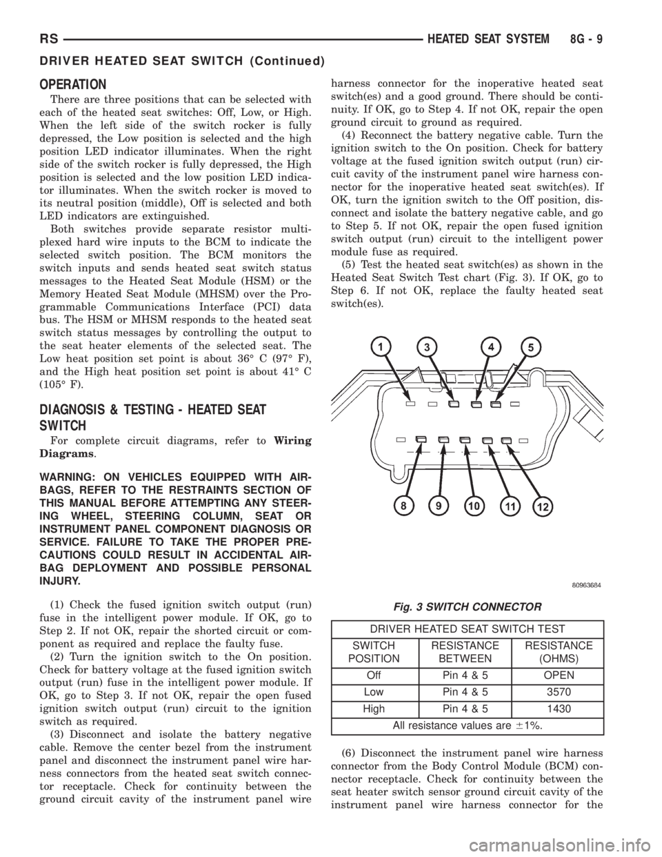
(5) Test the heated seat switch(es) as shown in the
Heated Seat Switch Test chart (Fig. 3). If OK, go to
Step 6. If not OK, replace the faulty heated seat
switch(es).
DRIVER HEATED SEAT SWITCH TEST
SWITCH
POSITIONRESISTANCE
BETWEENRESISTANCE
(OHMS)
Off Pin4&5OPEN
Low Pin4&53570
High Pin4&51430
All resistance values are61%.
(6) Disconnect the instrument panel wire harness
connector from the Body Control Module (BCM) con-
nector receptacle. Check for continuity between the
seat heater switch sensor ground circuit cavity of the
instrument panel wire harness connector for the
Fig. 3 SWITCH CONNECTOR
RSHEATED SEAT SYSTEM8G-9
DRIVER HEATED SEAT SWITCH (Continued)
Page 1908 of 4284
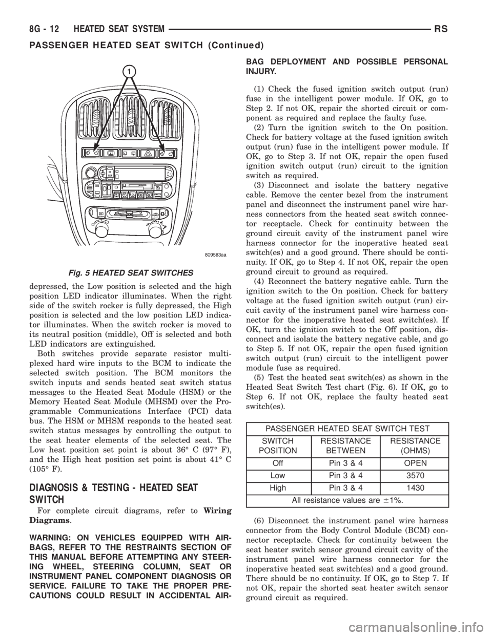
depressed, the Low position is selected and the high
position LED indicator illuminates. When the right
side of the switch rocker is fully depressed, the High
position is selected and the low position LED indica-
tor illuminates. When the switch rocker is moved to
its neutral position (middle), Off is selected and both
LED indicators are extinguished.
Both switches provide separate resistor multi-
plexed hard wire inputs to the BCM to indicate the
selected switch position. The BCM monitors the
switch inputs and sends heated seat switch status
messages to the Heated Seat Module (HSM) or the
Memory Heated Seat Module (MHSM) over the Pro-
grammable Communications Interface (PCI) data
bus. The HSM or MHSM responds to the heated seat
switch status messages by controlling the output to
the seat heater elements of the selected seat. The
Low heat position set point is about 36É C (97É F),
and the High heat position set point is about 41É C
(105É F).
DIAGNOSIS & TESTING - HEATED SEAT
SWITCH
For complete circuit diagrams, refer toWiring
Diagrams.
WARNING: ON VEHICLES EQUIPPED WITH AIR-
BAGS, REFER TO THE RESTRAINTS SECTION OF
THIS MANUAL BEFORE ATTEMPTING ANY STEER-
ING WHEEL, STEERING COLUMN, SEAT OR
INSTRUMENT PANEL COMPONENT DIAGNOSIS OR
SERVICE. FAILURE TO TAKE THE PROPER PRE-
CAUTIONS COULD RESULT IN ACCIDENTAL AIR-BAG DEPLOYMENT AND POSSIBLE PERSONAL
INJURY.
(1) Check the fused ignition switch output (run)
fuse in the intelligent power module. If OK, go to
Step 2. If not OK, repair the shorted circuit or com-
ponent as required and replace the faulty fuse.
(2) Turn the ignition switch to the On position.
Check for battery voltage at the fused ignition switch
output (run) fuse in the intelligent power module. If
OK, go to Step 3. If not OK, repair the open fused
ignition switch output (run) circuit to the ignition
switch as required.
(3) Disconnect and isolate the battery negative
cable. Remove the center bezel from the instrument
panel and disconnect the instrument panel wire har-
ness connectors from the heated seat switch connec-
tor receptacle. Check for continuity between the
ground circuit cavity of the instrument panel wire
harness connector for the inoperative heated seat
switch(es) and a good ground. There should be conti-
nuity. If OK, go to Step 4. If not OK, repair the open
ground circuit to ground as required.
(4) Reconnect the battery negative cable. Turn the
ignition switch to the On position. Check for battery
voltage at the fused ignition switch output (run) cir-
cuit cavity of the instrument panel wire harness con-
nector for the inoperative heated seat switch(es). If
OK, turn the ignition switch to the Off position, dis-
connect and isolate the battery negative cable, and go
to Step 5. If not OK, repair the open fused ignition
switch output (run) circuit to the intelligent power
module fuse as required.
(5) Test the heated seat switch(es) as shown in the
Heated Seat Switch Test chart (Fig. 6). If OK, go to
Step 6. If not OK, replace the faulty heated seat
switch(es).
PASSENGER HEATED SEAT SWITCH TEST
SWITCH
POSITIONRESISTANCE
BETWEENRESISTANCE
(OHMS)
Off Pin3&4OPEN
Low Pin3&43570
High Pin3&41430
All resistance values are61%.
(6) Disconnect the instrument panel wire harness
connector from the Body Control Module (BCM) con-
nector receptacle. Check for continuity between the
seat heater switch sensor ground circuit cavity of the
instrument panel wire harness connector for the
inoperative heated seat switch(es) and a good ground.
There should be no continuity. If OK, go to Step 7. If
not OK, repair the shorted seat heater switch sensor
ground circuit as required.
Fig. 5 HEATED SEAT SWITCHES
8G - 12 HEATED SEAT SYSTEMRS
PASSENGER HEATED SEAT SWITCH (Continued)
Page 1927 of 4284
INSTRUMENT CLUSTER
TABLE OF CONTENTS
page page
INSTRUMENT CLUSTER
DESCRIPTION............................1
OPERATION.............................1
DIAGNOSIS AND TESTING..................1
INSTRUMENT CLUSTER..................1
REMOVAL..............................11
INSTALLATION...........................11
CLUSTER LENS
REMOVAL..............................12INSTALLATION...........................12
MECHANICAL TRANSMISSION RANGE
INDICATOR
REMOVAL..............................12
INSTALLATION...........................12
RED BRAKE WARNING INDICATOR
DESCRIPTION...........................12
OPERATION.............................12
INSTRUMENT CLUSTER
DESCRIPTION
The instrumentation gauges are contained in a
subdial assembly within the instrument cluster. The
individual gauges are not serviceable. If one of the
cluster gauges becomes faulty, the entire cluster
would require replacement.
The mechanical instrument cluster with a tachom-
eter is equipped with a electronic vacuum fluorescent
transmission range indicator (PRND3L), odometer,
and trip odometer display.
The mechanical instrument cluster without a
tachometer is equipped with a cable operated trans-
mission range indicator (PRND21) and a vacuum
flourescent odometer display.
The instrument cluster is equipped with the follow-
ing warning lamps.
²Lift Gate Ajar
²Low Fuel Level
²Low Windshield Washer Fluid Level
²Cruise
²Battery Voltage
²Fasten Seat Belt
²Door Ajar
²Headlamp Out
²Coolant Temperature
²Anti-Lock Brake
²Brake
²Airbag
²Traction Control
²Autostick
OPERATION
Refer to the vehicle Owner's Manual for operation
instructions and conditions for the Instrument Clus-
ter Gauges.
DIAGNOSIS AND TESTING - SELF-
DIAGNOSTICS
The instrument clusters are equipped with a self
diagnostic test feature to help identify electronic
problems. Prior to any test, perform the Self-Diag-
nostic Test. The self diagnostic system displays
instrument cluster stored fault codes in the odometer
display, sweeps the gauges to the calibration points,
and bulb checks the warning indicators. When the
key is in the ON position with the engine not run-
ning, the MIL will remain illuminated for regulatory
purposes.
To activate the Self-Diagnostic program:
(1) With the ignition switch in the OFF position,
depress the TRIP ODOMETER RESET button.
(2) Continue to hold the TRIP ODOMETER
RESET button untilSofand a number (software ver-
sion number (i.e.Sof 3.2) appears in the odometer
window (about five seconds) then release the button.
If a fault code is present, the cluster will display it in
the odometer display. When all fault codes have been
displayed, the cluster will displayªendºin the odom-
eter display. Refer to the table to determine what
each trouble code means.
RSINSTRUMENT CLUSTER8J-1